Solaro Energy Solaro Aire SA-20WR-GAE User manual

Fan Install Pack
•A-BRT4: (4) Solar Panel Feet
•F-030: (4) 1.5” dual thread hex head rubber washer
screw
• F-018: (4) 0.5” self drilling phillips truss head screw
• F-SP003: (1) Rubber roof grommet
• F-016: (4) 1.25” self tapping phillips truss head screw
• F-030: (6) Dual thread rubber washer screw
Roof Grommet KitSolar Panel Mounting Pack
A. Solaro Aire™Gable Fan
B. 20, 30, 40 or 50 watt solar panel
C. 25ft. (7.6 m) Interconnect cable
•Ladder • Marker
• Drill • Caulking Gun
• Screw Driver • Water Proof Sealant
• Measuring Tape • Wire Strippers
• Drill Bit Set • Roofing Sealant
• #2 Screw Bit • 1/4” Hex Bit Driver
Helpful Hints:
Components:
Tools Needed:
Solar Panel
Solaro Aire™ Gable 25ft. Interconnect Cable
A. B. C.
WARNING: Take caution during installation. Please read
through ENTIRE steps before performing any work. Not
following the instruction can void the warranty and/or
cause serious injury. For professional help, please call
1-888-355-5SUN
F-030 F-018
• When determining the location of the solar panel, try to face the
panel towards the equator (South in the Northern Hemisphere or
North in the Southern Hemisphere). Large trees or other houses may
cause shading during certain times of the day.
SA-20WR-GAE
SA-30WR-GAE
SA-40WR-GAE
SA-50WR-GAE
SA-20WR-GA
SA-30WR-GA
The Solaro Aire™ Ventilation System will need some assembly before
it becomes operational. THE FAN BLADE WILL BEGIN TO OPERATE
AS SOON AS IT IS EXPOSED TO THE SUN. PLEASE KEEP HANDS
AND TOOLS AWAY FROM THE BLADE DURING THE INSTALLATION.
Important Precautions: • Always use caution when using tools and walking on roofs.
• Do not cut any structural members in the house.
• Always measure twice cut once.

Step 1: Positioning solar panel feet on solar panel
• Place a mark (using a pencil or sharpie) 4” (101.6 mm) from edge at
all four corners. (fig. 1.1)
• Gripper pad on the bracket (A-BRT4) will be pointed away from
back of the panel. (fig. 1.2)
• Drill the brackets in place with the #8 1 ½” (38.1 mm) (F-018) self
drilling phillips head screw. (fig. 1.3)
• Repeat for all four brackets (A-BRT4). (fig. 1.4)
Note: Do not use the Prepunch holes in the solar panel
along the long edge of the solar panel. to attach solar panel
feet to panel.
1.1
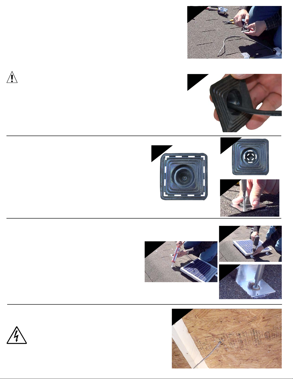
• Strip the wire of the protective sheathing and strip the wires. Twist
each end of the wires
• Unscrew the cover on the back of the panel and feed the wire
through. Tighten strain relief. (fig 2.1)
• Loosen terminal screws. Wrap the black wire to the (-) negative
screw terminal and red wire to the (+) positive screw terminal.
• Tighten screws. Wrap wires clockwise over the screw for a better
hold when it is tightened. (fig 2.2)
• Screw on the cover. Make sure the O-Ring creates a proper seal.
Warning: The cable is now live. Always keep the
contacts covered and separated so they cannot
contact each other and short the panel.
2.1
2.2
Step 3: Locating the Solar Panel on the roof
•Pick a location for the panel that maximizes the sun hitting it when
the light is wanted the most. Typically this means a South facing
roof in the Northern hemisphere.
• Roughly locate center of where panel will mount for cable
penetration. Make sure not to hit framing underneath. (fig. 3.1)
• Drill one ½” (12.7 mm) hole through the sheathing. (fig. 3.2)
3.1
3.2
1.2
1.3 1.4
Install solar panel on shingle roof
Step 2: Connecting the wire to the solar panel (When it’s
not factory installed)
Note: Use 1x roof grommet pack
Step 6: Mounting the Solar Panel
• Position the solar panel centered over the roof grommet.
•Using a sharpie, mark the four holes of the brackets.
•Add caulking to the four markings and reposition the panel
back into place. (fig 6.1)
• Fasten solar panel with rubber washer head screws
(F-030) through each mounting bracket. (fig 6.2 & 6.3)
Step 7: Running the cable
• Warning: Follow all state/local building codes
and electrical standards applicable to your
location.
Step 5: Add Sealant and screw down
• Place a continuous bead of roofing sealant along the bottom
surface of the roof grommet. (fig. 5.1)
• Add a generous glob of roofing sealant inside the roof grommet to
seal up the hole for the cable. (fig 5.2)
• Position the rubber grommet over the hole and screw it into place
using self tapping phillips truss head screws (F-016) on all four
corners. (fig 5.3)
5.1
4.1
5.2
5.3
6.1
7
6.2
6.3
• Route the interconnect cable (C) through the attic to the
location where the attic fan will be installed.
• Zip tie cable as needed for a safe and problem free run.
Step 4: Prep the Wire Penetration
• Snip o the top point of the rubber roof grommet
(F-SP003) with a pair of scissors, razor, or knife. (g 4.1)
• Slide the roof grommet up the cable until you are within about 1’
(30cm) of the solar panel junction box. (g. 4.2)
• Feed the interconnect cable through the hole until the roof grommet
is near the hole.
4.2
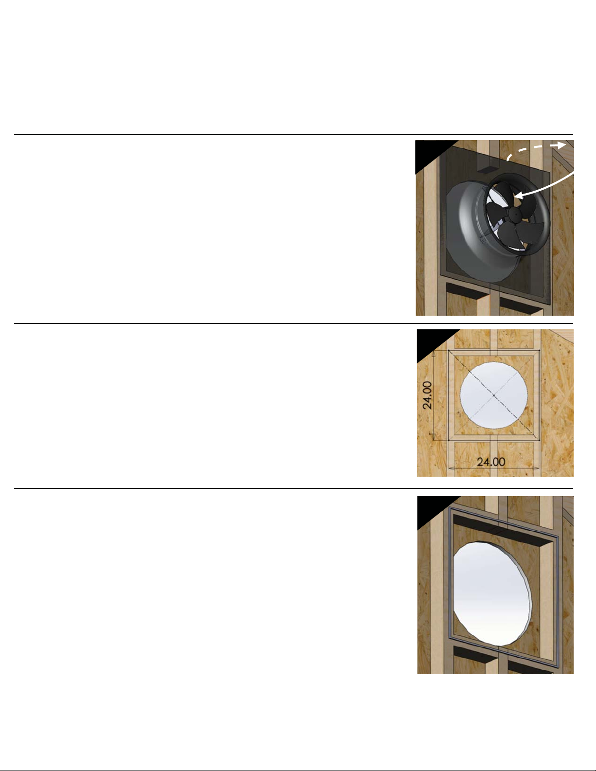
• Once a suitable location has been found, test fit the gable
fan (A) flashing for obstructions or large gaps where exhaust
can flow back into the attic. (dotted line fig. 1)
• Mark the outline of the flashing with a marker or scribe.
• Install additional framing where the flashing is not fully
supported and sealed on all 4 edges. This can typically be
done with 2x4 studs making a 24”x24” (61cm x 61cm) box.
• You can achieve slightly improved performance by using roof
sealer or foam weather-stripping to reduce blow-by (air that is
pushed through the fan and seeps out the sides instead of being
pushed through the gable vent and out the attic). Add any
sealer/foam to the frame to make handling the gable fan easier.
Step 1: Pick a location
Step 2: Add Base material if necessary
Step 3: Seal the ashing to the framing/gable vent (optional)
NOTE: The gable fan should be mounted on the inside of the attic just behind a traditional gable or other large vent. The flashing must seal to the
vent for optimal performance. Intake airflow can come from another gable vent on the opposite side of the house or from smaller vents (soffits
typically) spread out throughout the attic. Smaller, spread out vents may require additional intake venting further from the gable fan to avoid flow
favoring the closer vents which creates hotspots. Place the attic fan on the highest gable vent possible to make sure it pulls out the hotter air that
accumulates near the ridge.
1
2
3
Install Gable fan

• Place the gable fan in the previously marked position and screw it into
place with the 6 hex head, rubber washer screws (F-030) included with
the kit.
• Screw into the centers of the framing studs at the flashings 4 corners.
• The final 2 screws should be placed midway down the edge on either
side into the vertical framing.
• Strip off 3” (7.6cm) of cable jacket and about 0.25” (6.3mm) of insulation off each wire if it is
not already prepped.
• Connect the black wire from the solar panel to the black (or blue) wire of the gable fan
using the attached spring operated connectors.
• Connect the red wire from the solar panel to the red wire from the gable fan.
NOTE: Although not expressly needed for installation, the following steps are
highly recommended for the effective and safe operation of the solar attic fan.
WARNING: The wires from the solar panel will be LIVE. Avoid
allowing the leads to contact each other, yourself, or metal
objects.
WARNING: The fan may start to operate immediately after the connections
are made. Keep hand and other debris free from the blades to avoid
damage or personal injury.
Step 4: Mount the Gable Fan
Step 5: Wire the gable fan to the solar panel cable.
4
5
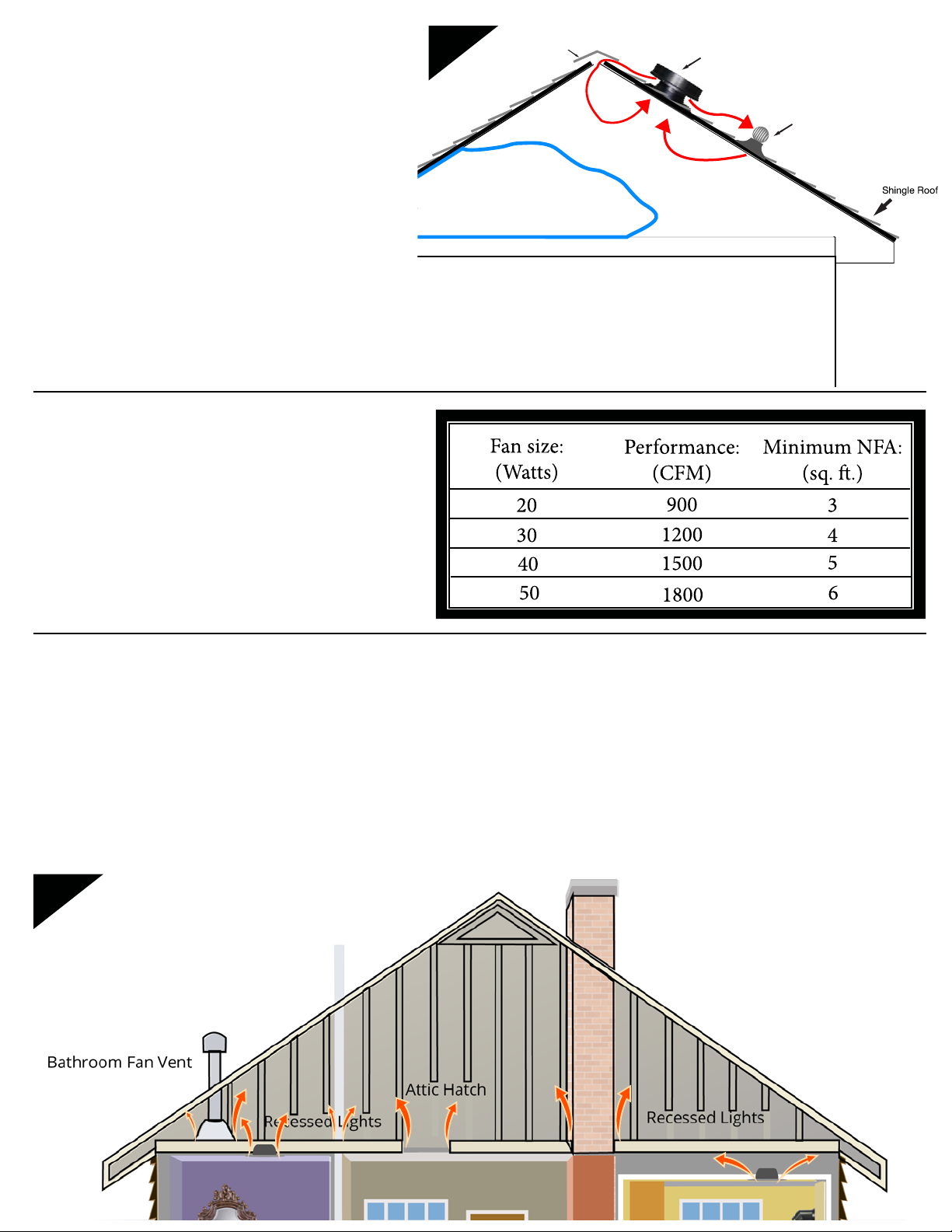
• Seal off any exhaust ventilation within about 15’ (5m) of
the solar attic fan to prevent the vent from re-breathing
the hot air exhausted by the fan. This is especially
important for ridge vents. Keep exhaust vents further
away open to allow passive ventilation when the fan
stops operating at night.
• Your solar attic fan requires at least 1 sq.ft. of Net Free
Area (NFA) for every 300CFM it is capable of. Install
additional vents if needed to match the capabilities of the
fan. Insufficient intake venting will cause the fan to pull
air from less desirable areas like conditioned air from the
home.
• Inspect the attic for possible leak points of conditioned air from the house into the attic. This could be can lights, holes, cracks, vents, etc.
Seal up any potential leak points according to local building code. Any conditioned air pulled into the attic from the house will diminish
the money saved from installing the fan by increasing the workload of the HVAC system.
Step 6: Fine Tune Exhaust Venting
Step 7: Fine Tune Intake Venting
Step 8: Seal the Attic
Living Area
Static Air: Unventilated
air due to re-breathing
Air vent
Solar attic vent
Ridge vent
6
Plumbing Stack Vent
8

This manual suits for next models
5
Table of contents
Other Solaro Energy Inverter manuals


