Solaro Energy SA-20WB-HPE User manual
™
•Drill •Reciprocating Saw
•Hammer •Caulk/Caulking Gun
•Screwdriver •Flat Bar
•Measuring Tape •Safety Goggles
•Pencil •Stud Finder
•Utility Knife
Tools Needed:
The Solaro Aire™ attic ventilation system is fully functional right
out of the box. THE FAN WILL BEGIN TO OPERATE AS SOON AS
IT IS EXPOSED TO THE SUN. PLEASE KEEP HANDS AND TOOLS
AWAY FROM THE BLADE DURING THE INSTALLATION.
Important Precautions:
• When determining the location of the solar panel, try to face the
panel towards the equator (South in the Northern Hemisphere or
North in the Southern Hemisphere).
• Avoid potential problems such as shading from large objects,
large trees, or other houses which may cause shading during cer-
tain times of the day.
•WARNING: Avoid all contact with the blades. Even a small bend
in the blades can cause severe vibration & premature motor failure.
• Do not cut any structural members in the house
• Always measure twice and cut once.
• Installation of the Solaro Aire™ should be centered on the roof.
• The center of the unit should be about 2ft ( 0.6 m) down from
roof ridge for maximum performance.
•Take precaution while working on the roof and with tools.
WARNING: Take caution during installation. Please
read through ENTIRE packet before performing
any work. Not following the instructions can void
the warranty and/or cause serious injury. For
professional help, please call 1-888-355-5SUN
Components & Parts List:
Helpful Hints:
Solaro Aire™ Embedded Series
Solaro Aire™ Tilt Series
Model Numbers:
SA-20WB-HPE
SA-20WB-LPE
SA-20WT-HPE
SA-20WT-LPE
SA-30WT-HPE
SA-30WT-LPE
SA-20WB-HP
SA-20WB-LP
SA-20WT-HP
SA-20WT-LP
SA-30WT-HP
SA-30WT-LP
A.
B.
OR
Fan Install Pack
•F-030: (6) 1.5” Dual thread rubber washer screw

Installation:
Please allow up to an hour for installation. Components and hardware are referenced in each step to the corresponding letters on
the parts list. (See components and parts list).
NOTE: Most rafters are spaced between 16” (41cm) to 24”(60.96cm) on center. Best performance will be achieved by plac-
ing the solar attic fan centered between the rafters. An alternative is to center it over a rafter. For either placement DO NOT
CUT INTO THE RAFTERS or any other structural member of the roof.
Step 1: Select a Location
The solar attic fan (A) should be installed with the center 2’ (61cm) below the roof ridge. Where possible the fan should be in a centralized
location (or equally spaced in multi- fan installations) so it pulls air equally from all parts of the attic.
Step 2: Mark the Location
• From inside the attic measure the desired location between rafters
where the center of the fan will sit.
• Measure 2’ (61cm) down from the ridge and mark the intersection of
the 2 lines.
• Drive a nail/screw through the roof or drill a small hole to transfer the
center mark to the outside.
Step 3: Draw the Hole
• Pop out the inner circle pressed into the cardboard protecting the
top of the solar attic fan. The circle is 16” (41cm) in diameter with a
small hole in the center.
• Place the cardboard template over the nail/screw from the previous
step, and trace the template with a pencil, sharpie, or scoring knife.
Step 4: Cut the Hole
• Cut along the template line with the reciprocating saw.
• CUT ONLY THE SHEATHING, NEVER CUT THROUGH
FRAMING MEMBERS.
• Cut along the rafters if the hole would extend past them.
There will be no appreciable drop in performance. (fig. 4.2)
• If the fan is centered over a rafter, use a smaller handsaw
to cut the sheathing above the rafter without harming the
structural member. (fig. 4.3)
2
3
4.1
4.2
4.2

Step 5: Clearance the Shingles
• Cut a horizontal 4” (10cm) slit at the 3 o’clock and 9 o’clock positions
using a razor knife. These slits allow the solar attic fan flashing to be
slid up under the upper courses of shingles.
• You can also remove 1-2” (2.5-5 cm) additional shingle material along
the top to help it slide in easier.
Step 6: Remove Obstructions Under the Shingles
• Remove any nails within 4” (10cm) of the top of the hole. Square
bases require additional clearance
• Dry fit the solar fan (A) flashing to test for other obstructions
stopping it from sliding all the way up. Low Profile (square) bases
should always have the sides vertical to properly slide under the
shingles.
Step 8: Place the Solar Attic Fan into Position.
• Carefully insert the solar attic fan under the upper rows of shingles
and over the lower rows.
Note: Do not let the roof seal smear on the roof until
it is in the final position. A poor seal may result if the
sealer is smeared as the fan is slid into position.
Step 7: Add Roof Sealer
• Add 2 generous, continuous beads of roof seal in 2 concentric rings
on the bottom of the flashing. The best seal involves placing the
beads about 1.5” (3.8cm) and 3” (7.6cm) from the inner transition
edge respectively.
5.1
5.2
7
6
LP Base
HP Base
8
WARNING: THE FAN WILL BEGIN TO OPERATE AS
SOON AS IT IS EXPOSED TO THE SUN. PLEASE KEEP
HANDS AND TOOLS AWAY FROM THE BLADE DURING
THE INSTALLATION.
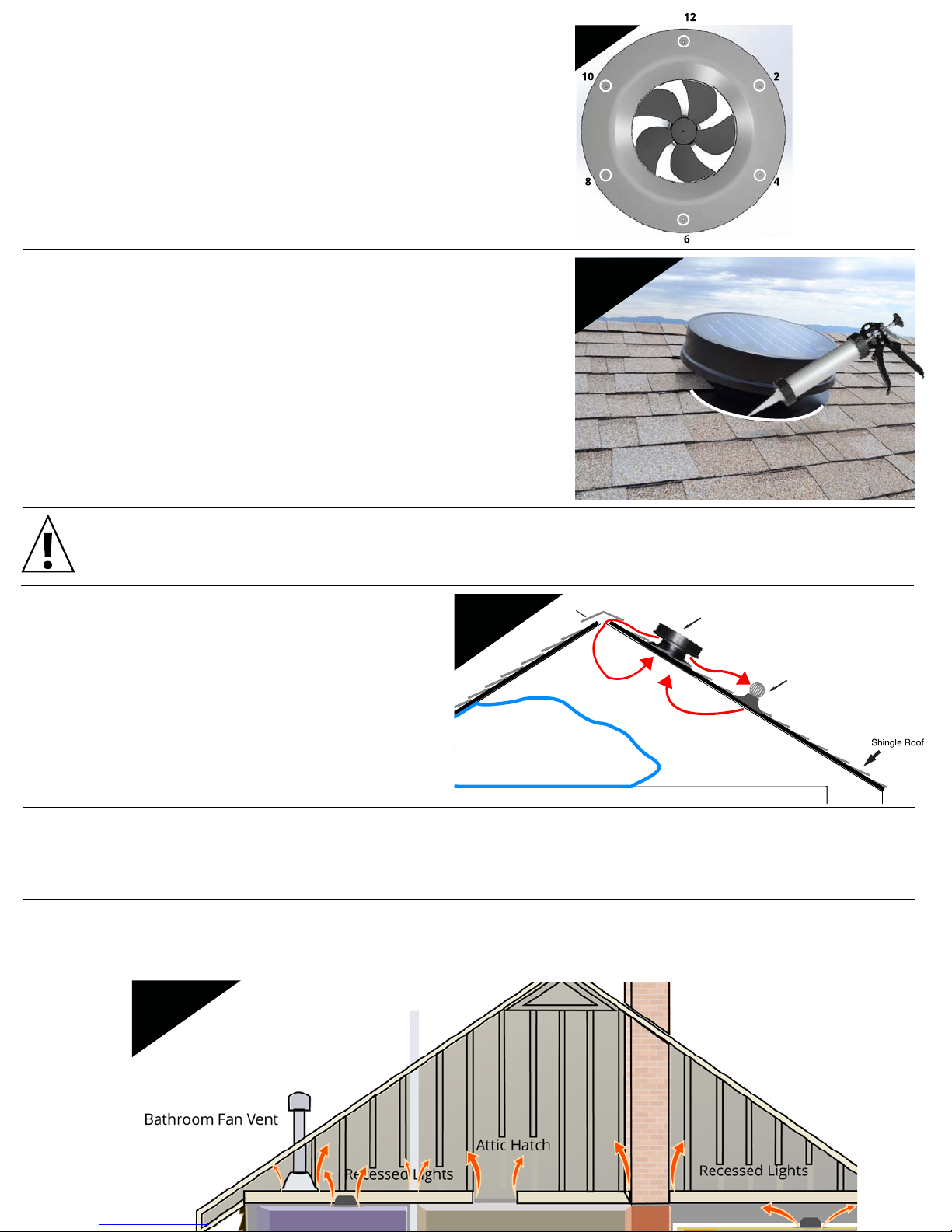
Step 9: Screw Fan Down
• Screw the flashing down using the 6 hex head, rubber washer
screws (F-030) included.
• Place the screws about 2” (5cm) in from the edge in the 2
o’clock, 4 o’clock, 6 o’clock, 8 o’clock, 10 o’clock, and 12 o’clock
positions.
• 2 and 10 positions should be placed under the shingles.
Step 10: Finishing Touches
• Caulk under any shingles that are loose to seal them to the
flashing.
• Caulk along the slits and where the shingles meet the raised
part of the flashing.
• Caulk over the heads of any screws still visible for added
weather and corrosion protection.
• Tilt Panel (if equipped): Loosen the wingnuts & adjust the
solar panel for optioned performance. Retighten wing nuts to
lock in position.
NOTE: Although not expressly needed for installation, the following steps are highly recommended for
the effective and safe operation of the solar attic fan.
Step 11: Fine Tune Exhaust Venting
• Seal off any exhaust ventilation within about 15’ (5m) of the
solar attic fan to prevent the vent from re-breathing the hot
air exhausted by the fan. This is especially important for ridge
vents. Keep exhaust vents further away open to allow passive
ventilation when the fan stops operating at night.
Step 12: Fine Tune Intake Venting
• Your solar attic fan requires at least 1 sq.ft. of Net Free Area (NFA) for every 300CFM it is capable of. Install additional vents if needed to
match the capabilities of the fan. Insufficient intake venting will cause the fan to pull air from less desirable areas like conditioned air from
the home.
Step 13: Seal the Attic
• Inspect the attic for possible leak points of conditioned air from the house into the attic. This could be can lights, holes, cracks, vents, etc.
Seal up any potential leak points according to local building code. Any conditioned air pulled into the attic from the house will diminish the
money saved from installing the fan by increasing the workload of the HVAC system.
Living Area
Static Air: Unventilated
air due to re-breathing
Air vent
Solar attic vent
Ridge vent
9
10
11
Plumbing Stack Vent
13

This manual suits for next models
11
Table of contents
Other Solaro Energy Inverter manuals

Popular Inverter manuals by other brands


SAT CONTROL
SAT CONTROL SM44M2HEL6M Instructions for installation and use

AlzaPower
AlzaPower APW-SC1A1D100 user manual

SMA
SMA sunny boy 2000hf-us installation guide

Mitsubishi Electric
Mitsubishi Electric FR-A500 Series Technical manual

Hitachi
Hitachi L300P Series Specifications

Sealey
Sealey TIG175HF instructions