14
A
A
A
A
MP
RA
WA
LB
J
K
IP
A
FH
E
D
G
GAS SUPPLY AND GAS PRESSURE
GAS SUPPLY PIPING INLET GAS PRESSURE
•Inlet gas pressure must be measured on the inlet side of the
valve at the inlet test point (IP). Remove plug from the inlet
test point, connect to manometer.
•Inlet gas pressure must conform to the following:
MINIMUM
GAS TYPE INLET PRESSURE
Natural 6” WC (15 cm WC)
LP/Propane 11” WC (28 cm WC)
MAXIMUM
GAS TYPE INLET PRESSURE
Natural 14” WC (35 cm WC)
LP/Propane 14” WC (35 cm WC)
IMPORTANT
•Gas piping must be installed in accordance with
local codes and/or the National Fuel Gas Code,
ANSI Z223.1 / NFPA 54-latest edition.
•All pipe connections must have pipe joint compound,
resistant to LP/propane gas action.
•Piping must have drip leg and a ground joint union.
•Local codes may require shut-off cock ahead of the
drip leg.
•Use only agency approved flexible gas connector
furnished with heater. See WARNING.
•Use swing or swivel joint in addition to rigid piping if
local codes prohibit use of a flexible gas connector.
•Installer provide 1/8” NPT plugged tapping for inlet
test point connection immediately upstream of gas
connection to heater.
•Isolate regulators, flexible gas connectors, and
heaters during high-pressure leak testing.
•All gas lines must be purged of air before startup.
•Inlet gas pressure at inlet test point (IP) cannot be more than
14 inches of Water Column (WC) (35 cm WC) (1/2 PSI),
confirmed by actual field test. (Heater on or off).
WARNING HIGH GAS PRESSURE
•When inlet gas pressure is greater than 14 in. WC (35 cm
WC) a positive lockout type high-pressure regulator must be
installed in the gas line ahead of the heater.
•High-pressure regulators will NOT turn off the flow of gas.
•Always check local codes for gas venting requirements for
high-pressure regulators.
•An over-pressure protection device (OPD) may be required in
certain jurisdictions.
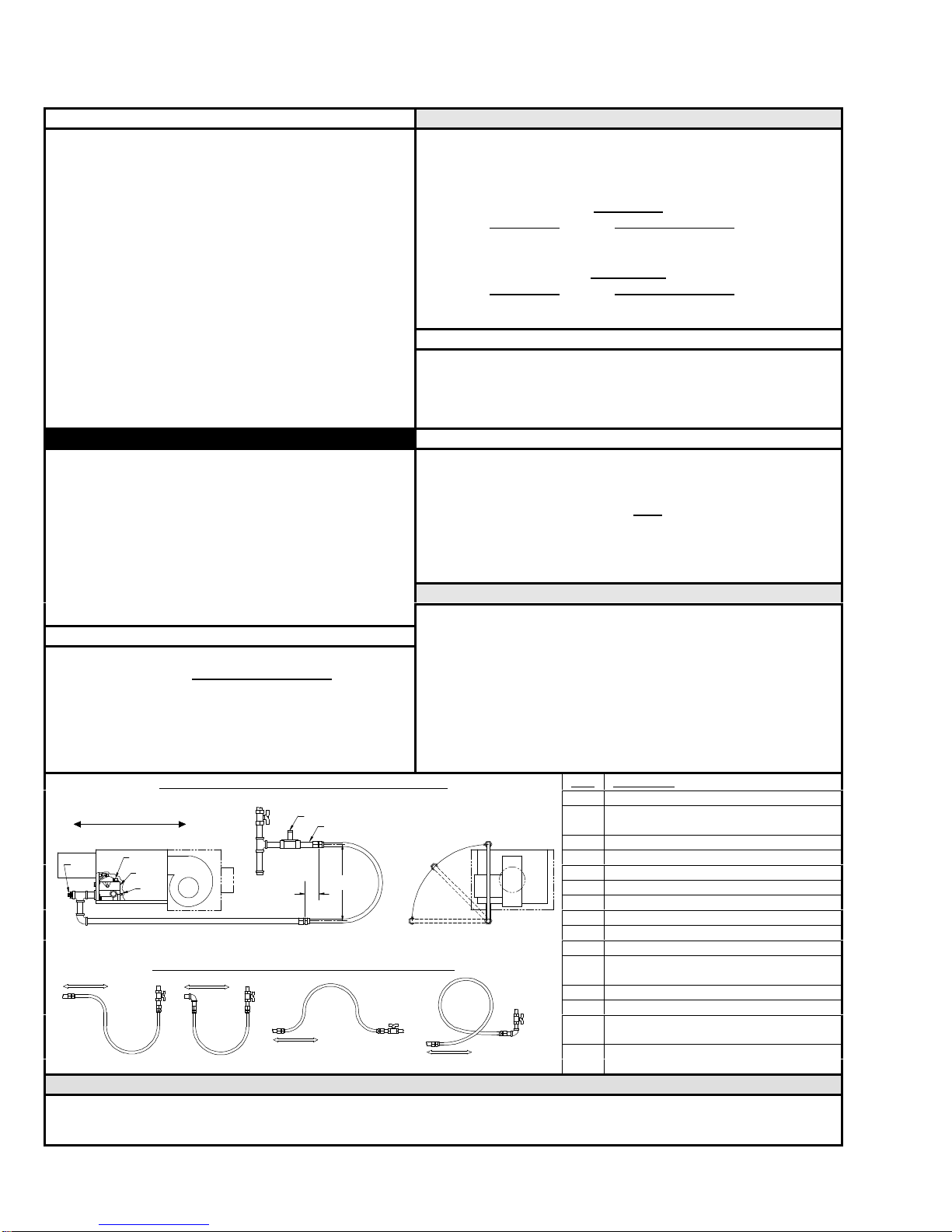
MANIFOLD GAS PRESSURE
•Connector must be installed in a “ ” configuration.
Use only the 24” (61 cm) or 36” (91 cm) long
connector of 1/2” (13 mm) nominal ID that was
furnished with the heater.
•Stress from expansion and contraction of heater
may cause excessive wear on the gas connection.
•For a heater 20 feet (6.1 m) long, heater tubes can
expand up to 1.1” (28 mm).
•It is important to maintain dimensions on drawing
below.
GAS PRESSURE MEASUREMENTS
•Use only a water or red oil manometer to make
measurements --- NOT A DIAL GAUGE.
•Make measurements and adjustments when this
heater and ALL other gas burning equipment
connected to the same gas meter are operating at
maximum capacity.
•Set inlet pressure first. Fluctuations in inlet pressure can
alter manifold pressure coming out of the gas valve.
•See drawing below for manifold pressure adjustment location.
•Loosen set screw, or remove plug form manifold test point
(MP); connect to manometer.
•Remove the slotted cap screw covering the manifold
adjustment.
•Turn adjustment screw clockwise to increase pressure or
counterclockwise to decrease pressure.
•Manifold Pressure setting is 3.5” WC (8.9 cm WC).
GAS CONNECTOR – CORRECT POSITIONS Item Description
AHeater movement
BGas supply nipple must be parallel to
heater movement
CHard piping
DFlexible gas connector
E3” (7.62 cm) maximum displacement
F12” (30 cm)
GVertical (as shown at left) – end view
HAlternate positions okay – end view
JGas cock shut-off (by others)
KDrip leg
GAS CONNECTOR – INCORRECT POSITIONS LRegulator required when pressure
exceeds 14” (35 cm) WC (by others)
IP Installer provide inlet test point
MP Manifold test point
RA Robert Shaw or Sit valve manifold
pressure adjustment
WRONG WRONG WRONG WRONG WA White Rodgers valve manifold pressure
adjustment
CAUTION
Excessive torque on the burner gas inlet pipe or manifold may cause damage to burner. Always use two (2) wrenches when
making pipe connections. Check for leaks with non-corrosive gas leak detection fluid. DO NOT USE FLAMES! Thoroughly
rinse with clean water to remove leak detection fluid.


