SolarPower24 Voltronic LIO II-4810 User manual

1
Solarpower24.it by Barba S.r.l. – via Locchi, 3F – 47122-Forlì – Italia
Tel/What’s up +39 05431995799 – web www.solarpower24.it – email
solarpower24@solarpower24.it
User Manual
Voltronic LIO II-4810
Standalone Lithium-Iron
Phosphate Battery Module
5.16kW
Version: 1.1

2
Solarpower24.it by Barba S.r.l. – via Locchi, 3F – 47122-Forlì – Italia
Tel/What’s up +39 05431995799 – web www.solarpower24.it – email
solarpower24@solarpower24.it
Table of Contents
1. Safety Precautions........................................................................... 3
1.1 Before Connecting ......................................................................... 3
1.2 In Use ............................................................................................. 3
2. Introduction ...................................................................................... 4
2.1 Features ......................................................................................... 4
2.2 Package Contents .......................................................................... 4
2.3 Specifications ................................................................................. 5
2.4 Product Indicator & Setting ............................................................ 6
3. Installation ........................................................................................ 9
3.1 Installation Environment................................................................. 9
3.2 Mounting the Modules.................................................................. 10
3.3 Wiring Configuration ........................................................................ 13
3.4 Wiring Diagrams of Diverse Applications ........................................ 18
4. Start-Up/Shut-Off the Battery Module .......................................... 22
4.1 Start up the battery module ............................................................. 22
4.2 Shut-off the battery module ............................................................. 22
5. Trouble Shooting ................................................................................ 23

3
Solarpower24.it by Barba S.r.l. – via Locchi, 3F – 47122-Forlì – Italia
Tel/What’s up +39 05431995799 – web www.solarpower24.it – email solarpower24@solarpower24.it
Thank you for purchasing LIO II-4810 Lithium battery module. Please read this manual before you install the battery.
Follow the instruction carefully during the installation process.
1. Safety Precautions
Reminder
1). It is very important and necessary to read the user manual carefully before installing or using the battery. Failure to
do so or to follow any of the instructions or warnings in this document can result in electrical shock, serious injury,
or death, or can damage the battery, potentially rendering it inoperable.
2) If the battery is stored for a long time, it is required to charge them every six months, and the SOC should be no less
than 90%;
3) Battery needs to be recharged within 12 hours, after fully discharged;
4) Do not expose cable outside;
5) All the battery terminals must be disconnected for maintenance;
6) Do not use cleaning solvents to clean the battery;
7) Do not expose battery to flammable or harsh chemicals or vapors;
8) Do not paint any part of the battery, include any internal or external components;
9) Do not connect the battery with PV solar wiring directly;
10) The warranty claims are excluded for direct or indirect damage due to the items above.
11) Any foreign object is prohibited to insert into any part of the battery.
Warning
1.1 Before Connecting
1) After unpacking, please check the product and packing list first, if the product is damaged or missing parts, please
contact the local retailer;
2) Before installation, be sure to cut off the grid power and make sure the battery is in the turned-off mode.
2) Wiring must be correct. Do NOT misconnect the positive and negative cables, and ensure no short circuit with the
external device.
4) It is prohibited to connect the battery and AC power directly.
5) The embedded BMS in the battery is designed for 48VDC, please DO NOT connect the battery in series.
6) Please ensure the electrical parameters of the battery system are compatible with related equipment.
7) Keep the battery away from water and fire.
1.2 In Use
1) If the battery system needs to be moved or repaired, the power must be cut off and the battery is completely
shutdown
2) It is prohibited to connect the battery with a different type of battery
3) It is prohibited to put the batteries working with faulty or incompatible inverter;
4) It is prohibited to disassemble the battery (QC tab removed or damaged);
5) In case of fire, only dry powder fire extinguisher can be used, liquid fire extinguishers are prohibited.
6) Please do not open, repair, or disassembly the battery except staff authorized. We do not undertake any
consequences or related responsibility which because of violation of safety operation or violating of design,
production, and equipment safety standards.
4
Solarpower24.it by Barba S.r.l. – via Locchi, 3F – 47122-Forlì – Italia
Tel/What’s up +39 05431995799 – web www.solarpower24.it – email solarpower24@solarpower24.it
Expansion Bolt
M10 (x4)
Fixing Plates for
Stand feet
(Left x1, Right x1)
SNAP bushing
(x2)
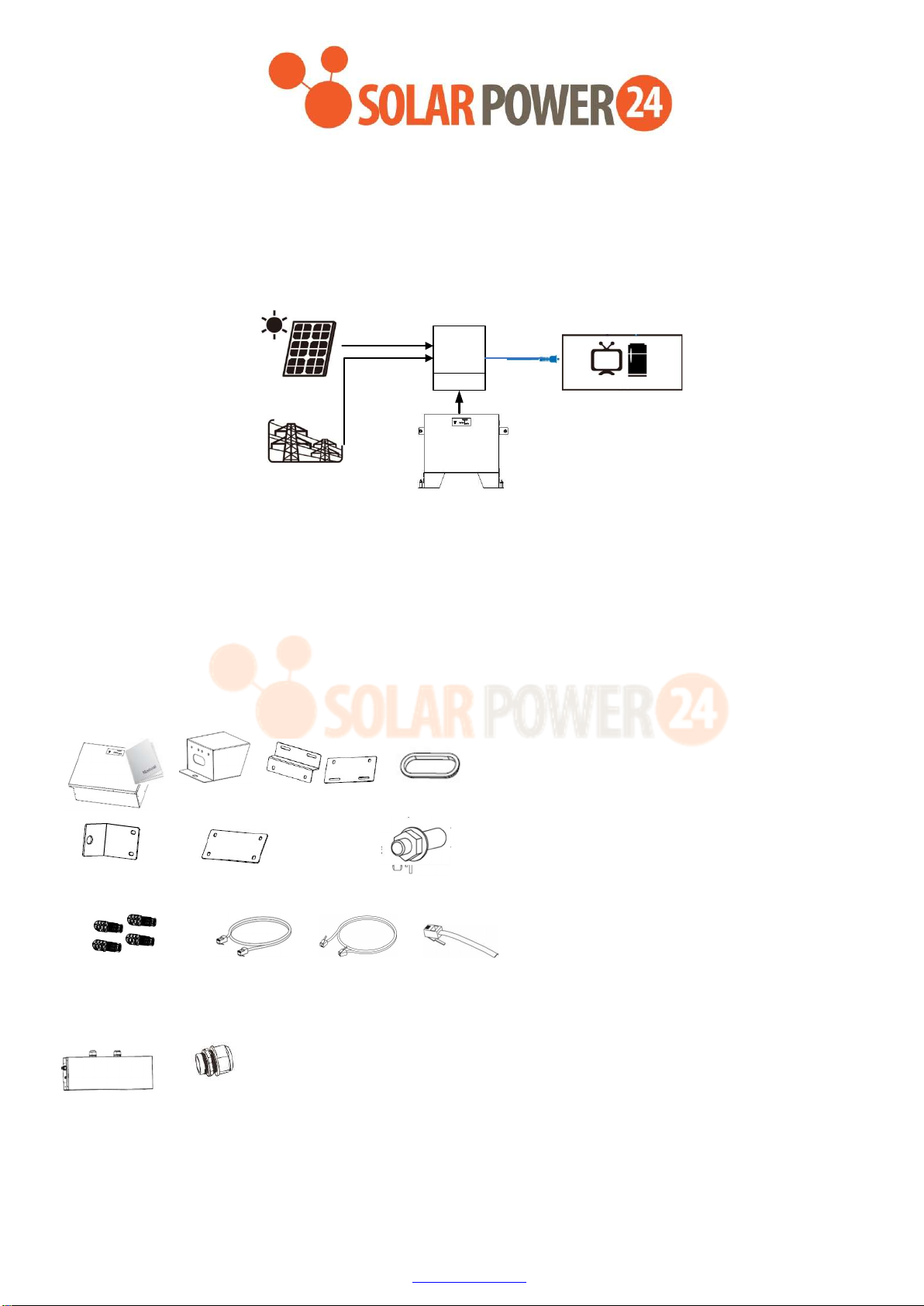
2. Introduction
LIO II-4810 Lithium iron phosphate battery modules are new energy storage products. It is designed to integrate with
reliable inverter modules.
It is built-in smart BMS battery management system, which can manage and monitor cells’ information including voltage,
temperature, current, etc. Moreover, BMS can balance cells charging and discharging to extend cycle life. Battery
modules can be used alone or in parallel, to expand capacity for different requirements.
PV Modules
Battery Modules
Public Grid
Inverter
Home Appliances
2.1 Features
Non-Toxic, non-polluting, and friendly to the environment.
LiFeO4 cell material, safety performance, and long cycle life.
Smart BMS protection functions: over-discharge, high temperature, over-charge, over-current.
Flexible configuration, multiple battery modules can be easily stacked and added for energy expansion.
Working temperature range is from 0°C to 50°C with excellent discharge performance and cycle life.
2.2 Package Contents
The packaging is recyclable, save it for reuse or dispose of it properly.
Battery Module Manual Stand Feet (x2)
L-type Brackets (x2) Fixing Plates (x2) Screws (x20)
External Battery connectors RJ45 cable RJ11 cable RJ11 Jumper
(BAT+ x2, BAT- x2)
PDU module can be purchased separately. Following contents will be included in its separately package:
PDU Module Cable Gland (x2)

5
Solarpower24.it by Barba S.r.l. – via Locchi, 3F – 47122-Forlì – Italia
Tel/What’s up +39 05431995799 – web www.solarpower24.it – email solarpower24@solarpower24.it
2.3 Specifications
Model LIO II-4810
Capacity (Wh) 5120 Wh
PARAMETERS
Nominal Voltage 51.2 VDC
Typical Capacity(Ah) 100 Ah
Full Charge Voltage
(FC) 56 V ± 0.1 V
Full Discharge
Voltage (FD) 42 V
Max. Continuous
Discharge Current 150 A
Max. Peak Discharge
Current 192 A at 1min
Protection BMS, Breaker
Max. Charge Voltage 52.5 V ± 0.1 V
Max. Charge Current 100 A
Standard Charge
Method
0.2C CC (Constant Current) charge to FC, CV
(Constant Voltage) charge till charge current
decline to <0.05C
Inner Resistance ≤20mΩ
Storage Temperature
-20ºC ~ 60 ºC
20°C±5°C is the recommended storage
temperature
Dimension
(D x W x H) mm 185 x 540 x 420
Dimension with stand
feet
(D x W x H) mm
185 x 540 x 530
Net Weight (kg) 48
Operation
Temperature
Charge : 0ºC ~ 50 ºC
Discharge : 0ºC ~ 50 ºC
Communication RS485 (RJ45), extension port (RJ11)
Certifications UN38.3, IEC 62619

6
Solarpower24.it by Barba S.r.l. – via Locchi, 3F – 47122-Forlì – Italia
Tel/What’s up +39 05431995799 – web www.solarpower24.it – email solarpower24@solarpower24.it
2.4 Product Indicator & Setting
1 Manual power on/off button - to wake up or shut down the battery module.
If battery module is off, press and hold the button over 5 seconds to turn on the module.
If battery module is working, press and hold the button for approximately 5 seconds to shut down the
module.
2 Battery Level LEDs - Indicates battery level. Please refer to the LED indicator table for the details.
3 Battery Status LEDs - Indicates battery module status. Please refer to the LED indicator table for the details.
LED Indicator:
Battery Status
Battery Status
LEDs Battery Level LEDs
Status SOC ON ALARM LED1
LED2 LED3
LED4
Normal
Mode
Charging
0%~25% ON OFF Flash OFF OFF OFF
26%~50% ON OFF ON Flash OFF OFF
51%~75% ON OFF ON ON Flash OFF
76%~100% ON OFF ON ON ON Flash
Discharging
0%~25% ON OFF ON OFF OFF OFF
26%~50% ON OFF ON ON OFF OFF
51%~75% ON OFF ON ON ON OFF
76%~100% ON OFF ON ON ON ON
Alarm
mode
Warning - OFF Flash -
Fault
-
OFF
ON
-
Power Off
-
OFF
OFF
OFF
OFF
OFF
OFF
4 External Battery Connector
There are two sets of battery connectors in parallel. Positive terminals are marked in ”BAT+” and Negative terminals
are marked in “BAT-”.
5 RS485 Port (BMS Communication Port)
Connector type: RJ45
Function: communication between battery module and inverter module.

7
Solarpower24.it by Barba S.r.l. – via Locchi, 3F – 47122-Forlì – Italia
Tel/What’s up +39 05431995799 – web www.solarpower24.it – email solarpower24@solarpower24.it
Pin Definition:
PIN Definition
1 RS485B
2 RS485A
3 NC2
4 RS485B
5 RS485A
6 PresentA
7 PresentB
8 NC1
6 Extension Port
Connector type: RJ11
Function: BMS signal transmission for battery module and for battery capacity extension in parallel.
Pin Definition
PIN Definition
1 CANH
2 CANL
3 PresentA
4
PresentB
5 NC
6 NC
8
Solarpower24.it by Barba S.r.l. – via Locchi, 3F – 47122-Forlì – Italia
Tel/What’s up +39 05431995799 – web www.solarpower24.it – email solarpower24@solarpower24.it
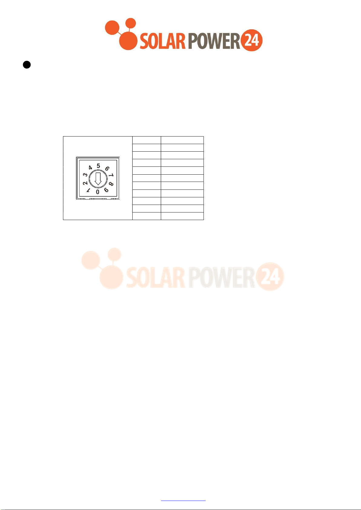
7 ID Switch
ID Switch indicates the unique ID code for each battery module. It's required to assign a unique ID to each
battery module for normal operation.
We can set up the ID code for each battery module by rotating the PIN number on the ID switch. From
number 0 to 9, the number can be random; no particular order.
If more than one battery module in the parallel system, the battery pack connected to the inverter module is
the Master battery and the ID code should be set as 0. The ID code of the remaining battery module MUST
be unique. Do not set the same number for 2 battery modules in the parallel system.
Maximum 10 battery modules can be operated in parallel.
PIN Definition
0 0x0F
1 0x0E
2 0x0D
3 0x0C
4 0x0B
5 0x0A
6 0x09
7 0x08
8 0x07
9 0x06

9
Solarpower24.it by Barba S.r.l. – via Locchi, 3F – 47122-Forlì – Italia
Tel/What’s up +39 05431995799 – web www.solarpower24.it – email solarpower24@solarpower24.it
3. Installation
3.1 Installation Environment
Make sure that the installation environment meets the following conditions:
The area is completely waterproof.
The floor is flat and level.
There are no flammable or explosive materials nearby.
The ambient temperature is within the range of 0~50°C.
The temperature and humidity are maintained at a constant level.
There is minimal dust and dirt in the area.
Caution:
If the ambient temperature is out of the operating range, the battery module will stop operate to protect itself. The
optimal temperature range for the battery module to operate is 0°C to 50°C. Frequent exposure to harsh temperatures
may deteriorate the performance and shorten the life cycle of the battery module.

10
Solarpower24.it by Barba S.r.l. – via Locchi, 3F – 47122-Forlì – Italia
Tel/What’s up +39 05431995799 – web www.solarpower24.it – email solarpower24@solarpower24.it
3.2 Mounting the Modules
Step 1: Clip two SNAP bushings into the stand feet. Then, fix two fixing plates on the stand feed (both sides) with eight
screws. finally, fix two L-type brackets on the battery module (both sides) with four screws.
Step 2: Install one battery module by following below steps.
(a) Use a Ø13mm drill to drill holes about 60mm deep according to the distance indicated on the below chart. Drill
two holes on the floor first, then drill two holes on the wall. If there is one more battery module to be stacked up,
drill two holes at a vertical distance of 420mm.
(b) Push four expansion bolts into the Ø13mm holes drilled on the previous step.
(c) Remove nut, spring washer and flat washer.
583
.00mm
85
.
00
mm
85
.
00
mm
612
.
5
mm
612
.
5
mm
420
.00mm
410
.
00
mm
Floor
Wall

11
Solarpower24.it by Barba S.r.l. – via Locchi, 3F – 47122-Forlì – Italia
Tel/What’s up +39 05431995799 – web www.solarpower24.it – email solarpower24@solarpower24.it
(d) Take assembled battery module (in step 1) and put on the ground. Align the hole on fixing plate with the two expansion bolts
on the ground. Align the hole on L-type bracket with two expansion bolts on the wall. Pass through the remaining bolt in the
floor and wall. Then, screw back the nut, spring washer, and flat washer
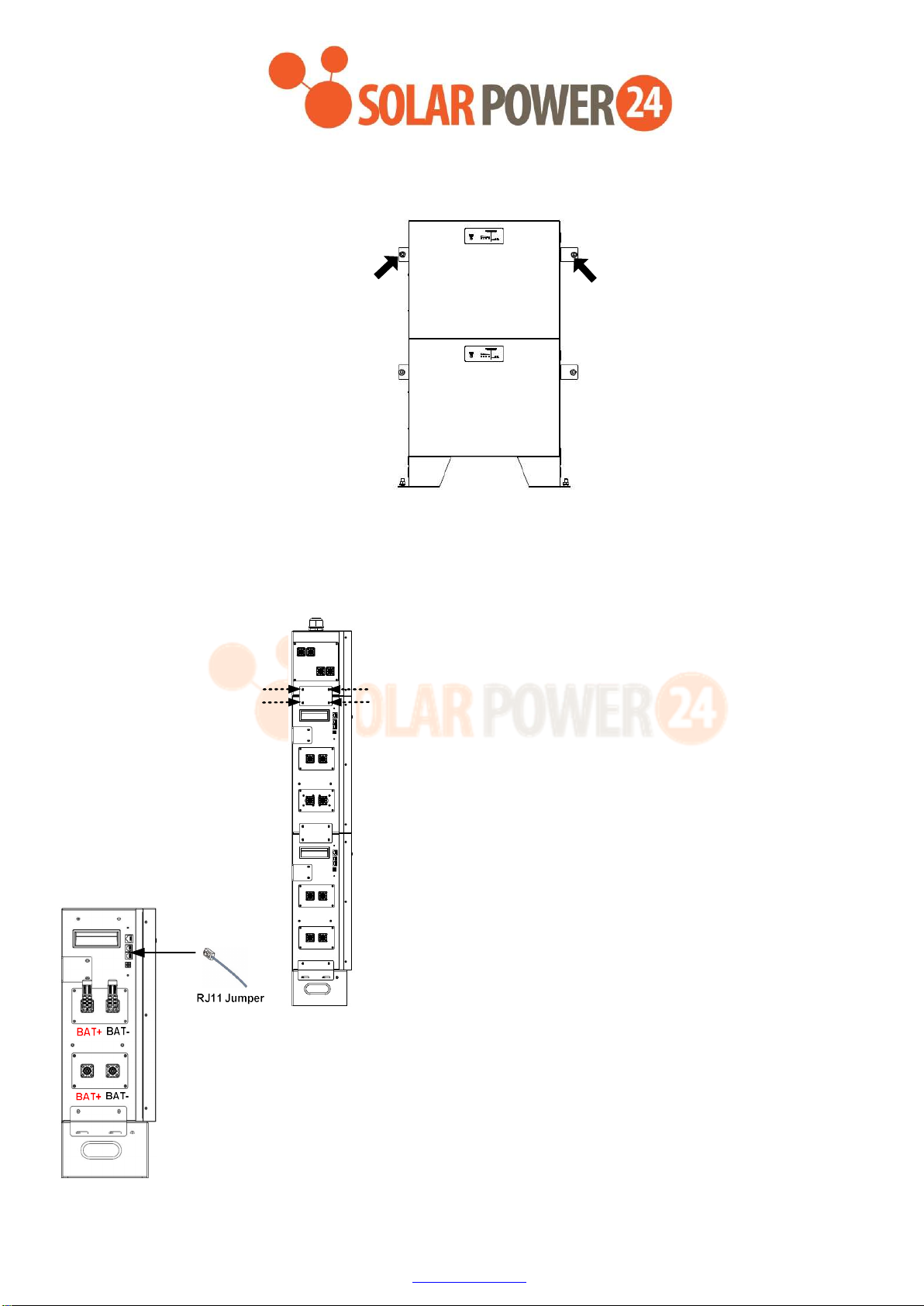
Step 3 (If more than one battery module is connected):
For a single battery module connection, please skip this step! If more than one battery module is connected, please
follow the instructions below:
(a) Put the additional battery module on the top of battery module installed on the ground. Make sure they are
aligned well.
(b) Install one fixing plate to fix two battery
modules with four screws as following the
picture shown.

12
Solarpower24.it by Barba S.r.l. – via Locchi, 3F – 47122-Forlì – Italia
Tel/What’s up +39 05431995799 – web www.solarpower24.it – email solarpower24@solarpower24.it
x
Additional
Battery Module
(c) Follow the same procedure as step (b) to fix the other side.
13
Solarpower24.it by Barba S.r.l. – via Locchi, 3F – 47122-Forlì – Italia
Tel/What’s up +39 05431995799 – web www.solarpower24.it – email solarpower24@solarpower24.it
(d)
(e) Refer to Step 2, fix the top battery module on the wall with two expansion bolts.
(f) If there are more battery modules installed, repeat steps (a) to (d).
Step 4 (If an optional PDU module is required in the system): Stack the PDU module on the top of all battery
modules. Install two fixing plates (supplied in PDU module package) on both sides of the modules with eight screws.
3.3 Wiring Configuration
Step 1: Insert the supplied RJ11 jumper into one of the extension port on the top of the battery
module.
*It's required to connect to the battery module for normal operation.
Step 2 (If multiple battery modules are in parallel): Insert RJ11 cable to connect the extension port of the
master battery module*. The other end connects to the extension port of the #2 battery module. If there are more
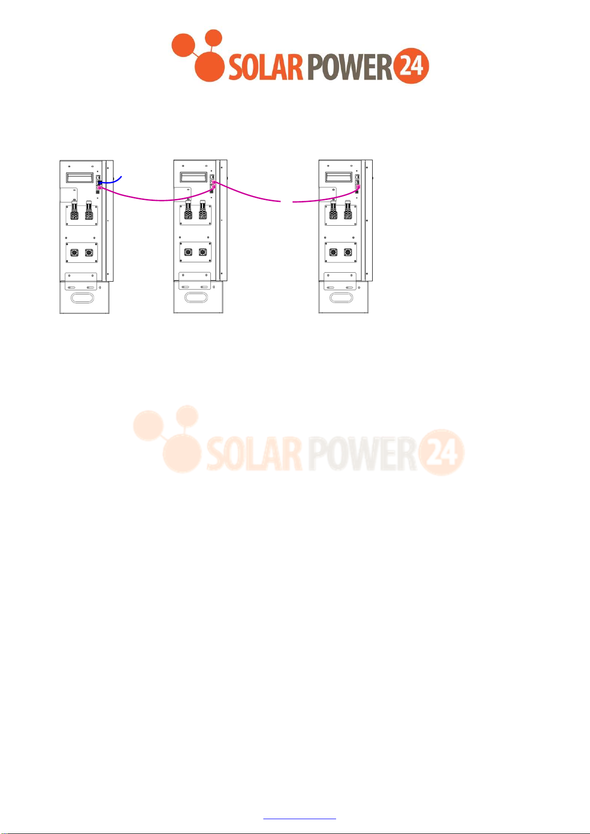
14
Solarpower24.it by Barba S.r.l. – via Locchi, 3F – 47122-Forlì – Italia
Tel/What’s up +39 05431995799 – web www.solarpower24.it – email solarpower24@solarpower24.it
Master battery
module
#1 #2 #10
battery modules are connected in the system, repeat this step to connect more battery modules.
Caution:The battery module connected to the power module is the Master battery and the ID code should be set as 0.
BAT+ BAT-
BAT+ BAT-
BAT+ BAT-
BAT+ BAT-
BAT+ BAT-
BAT+ BAT-
RJ11 Jumper
···
RJ11 cable RJ11 cable
15
Solarpower24.it by Barba S.r.l. – via Locchi, 3F – 47122-Forlì – Italia
Tel/What’s up +39 05431995799 – web www.solarpower24.it – email solarpower24@solarpower24.it
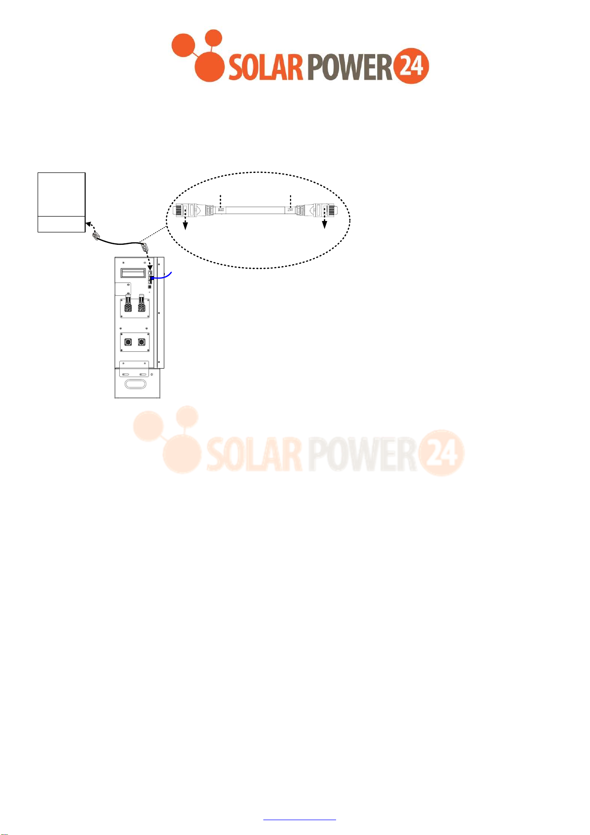
Step 3: Insert the supplied RJ45 cable into the RJ45 communication port on the master battery module. The other end
connects to BMS communication port on the inverter module.
Caution: “BAT” and “INV” are marked on the RJ45 cable. Make sure connect the battery module and inverter module
with correct end.
Inverter
BAT+ BAT-
BAT+ BAT-
RJ45 cable
RJ11 Jumper
BAT INV
The end connects to
inverter mo dule
The end connects to
battery module
Master battery module
Caution: CAUTION: If more than one battery modules are connected for capacity extension, the battery module
connected to inverter module directly will be defined as "Master battery module". Be sure to set ID number for Master
battery module as "0".

16
Solarpower24.it by Barba S.r.l. – via Locchi, 3F – 47122-Forlì – Italia
Tel/What’s up +39 05431995799 – web www.solarpower24.it – email solarpower24@solarpower24.it
Master battery
module
#1 #2 #10
Step 4: Please follow below steps to prepare battery cable with supplied external battery connectors. The cable length
should be prepared based on the real distance between battery module and inverter module.
The recommended cable size is listed as below:
Wire Size Cable mm2
1*4AWG 25
(a) Loosen and disassemble the plug of the supplied battery connector.
(b) Insert the battery cable through the tunnel and housing, and strip battery cable 11.5±0.2mm.
11.5±0.2
(c) Crimp the cable and the plug with a proper crimping tool (ex. hydraulic clamp) together into a hexagon shape as
shown in below chart. Then, move the housing toward plug and tighten them.
7.8±0.1
(d) Use battery cable to connect the battery module and inverter module. Make sure the polarity of battery module
are correctly connected.
RED connector to the positive terminal (+)
BLACK connector to the negative terminal (-)
If more than one battery modules are connected, use battery cable to connect master battery module and
remaining battery module one by one.

17
Solarpower24.it by Barba S.r.l. – via Locchi, 3F – 47122-Forlì – Italia
Tel/What’s up +39 05431995799 – web www.solarpower24.it – email solarpower24@solarpower24.it
(e) After connecting all cables, the battery modules are ready for DC output.

18
Solarpower24.it by Barba S.r.l. – via Locchi, 3F – 47122-Forlì – Italia
Tel/What’s up +39 05431995799 – web www.solarpower24.it – email solarpower24@solarpower24.it
3.4 Wiring Diagrams of Diverse Applications
(1) Single battery module connection with a max 150A current wiring:
(suitable for ≤6KW Inverter)

19
Solarpower24.it by Barba S.r.l. – via Locchi, 3F – 47122-Forlì – Italia
Tel/What’s up +39 05431995799 – web www.solarpower24.it – email solarpower24@solarpower24.it
(2) Two-battery module connection for a longer backup time with a max 150A current wiring:
(suitable for ≤6KW Inverter)
Inverter
BAT+ BAT-
BAT+ BAT-
BAT+ BAT-
BAT+ BAT-
Master
Battery Module
RJ45 cable
RJ11 Jumper
RJ11 cable

20
Solarpower24.it by Barba S.r.l. – via Locchi, 3F – 47122-Forlì – Italia
Tel/What’s up +39 05431995799 – web www.solarpower24.it – email solarpower24@solarpower24.it
(3) Two-battery module connection for a larger-capacity Inverter:
(suitable for >6KW Inverter)
*PDU module is required for combining battery pack current!
Inverter
BAT+ BAT-
BAT+ BAT-
BAT+ BAT-
BAT+ BAT-
Master
Battery Module
RJ45 cable
RJ11 Jumper
PDU Module
RJ11 cable
BAT+ BAT-
BAT+
BAT-
Optional output I:
Optional output II:
Table of contents


