solarwholesaler RV User manual

Solar Installation Guide - RV
- Motor Homes
- Trailers
- Boats
SolarWholeSaler.ca
SolarWholeSaler.ca

Index
Tools and Hardware Needed........................1
Parallel Solar Panel Connections......................2
Serial Solar Panel Connections............................3
Inverter Connection Diagram.............................4
Mounting Kit Installation....................................5
Battery Connection Diagrams...................6

Tools
Power Drill
Z-Bracket
Mounting HardWare
3/8 Nut Driver Wire Cutters
9/64 Drill Bit
Page 1
Tools & Hardware Needed
Stainless Steel
Nuts & Bolts
10 x 1 Inch
Wood/Sheet Metal Screw
Quad Caulking
(Advanced Formula
Sealant & Glue)
Caulking Gun

Layout & Configuration
1. Figure out how many panels you will need, and the amount of panels you can actually fit on the space you will be installing them.
2. Measure how much wire you will need, by measuring where and how the wire will run to the charge controller than to the batteries.
3. Batteries to Inverter (Inverter is typically very close to batteries because of the amount of Amperage needed to run them.)
Solar Panel Single & Parallel Configurations
1. Single Panel Connection
2. Double Panel Connection
3. Triple Panel Connection
Single Panel Connection Double Parallel Panel Connection
(Increases Amperage)
12 Volt Solar Panels
Mc4 Serial Connectors
12 Volt Battery
12 Volt Controller
12 Volt Solar Panels
Mc4 Serial Connectors
12 Volt Solar Panels
Mc4 Parallel Connectors
Triple Parallel Panel Connection
(Increases Amperage)
12 Volt Battery
12 Volt Controller
12 Volt Solar Panels 12 Volt Solar Panels
Mc4 Triple Parallel Connectors
Mc4 Serial Connectors
12 Volt Solar Panels
Page 2
Planning & Starting The Installation
Resettable Fuse Breaker
(Ensures line protection
incase of any dead shorts)
Must be in the positive line
and as close to the battery
terminal as possible.
Resettable Fuse Breaker
(Ensures line protection
incase of any dead shorts)
Must be in the positive line
and as close to the battery
terminal as possible.
12 Volt Battery
12 Volt Controller
Resettable Fuse Breaker
(Ensures line protection
incase of any dead shorts)
Must be in the positive line
and as close to the battery
terminal as possible.

MPPT Charge Controller Serial & Parallel Connections
Double Panel Serial Connection
12 Volt Battery
12 Volt Controller
Mc4 Serial Connectors
Page 3
Planning & Starting The Installation
37 Volt Solar Panels 37 Volt Solar Panels
This diagram shows two 37 Volt Solar Panels connected in series which increases the voltage to 74 Volts.
The MPPT charge controller will match the battery voltage and convert the rest into Amperage allowing it to use
up to 97 % of the solar panel power. The efficiency can be up to 30% more than regular PWM charge controller.
Resettable Fuse Breaker
(Ensures line protection
incase of any dead shorts)
Must be in the positive line
and as close to the battery
terminal as possible.
4 - Panel Serial & Parallel Connection
12 Volt Battery
12 Volt Controller
37 Volt Solar Panels 37 Volt Solar Panels
Resettable Fuse Breaker
(Ensures line protection
incase of any dead shorts)
Must be in the positive line
and as close to the battery
terminal as possible.
37 Volt Solar Panels 37 Volt Solar Panels

12 Volt Battery
12 Volt Controller
12 Volt Solar Panels
12V-DC Inverter Terminals
Battery/Protection Fuse (from battery to inverter)
(Fuse needs to be as close to battery terminal as possible)
Fuse Amp size is based on inverter Wattage.
(Total Watts divided by Volts = “Fuse Amp Size”)
Some Examples:
A: 1500 Watt Inverter = 125A Fuse
B: 2500 Watt Inverter = 220A Fuse
C: 3500 Watt Inverter = 300A Fuse
D: 5000 Watt Inverter = 425A Fuse
12 Volt Inverters
Inverter Installation Diagram
- Batteries fasten to inverter terminals using 3/8 connectors normally. (Terminal size is based on inverter & Battery Type)
- Cable thickness is determined by Length Volts and Amperage. Good Practice to use 00AWG Wire no longer than 4 feet.
- Any wires/cables coming from battery power source need to have a protective fuse with the positive line.
00 Awg Wire
no longer than 4 foot
Page 4
-----------------------------------------
-----------------------------------------
------------------------------------------------------------
------------------------------------------------------------
Inverter Connection Diagram
Inverter Connection Diagram
Inverter Connection Diagram
Proper rated fuse
Resettable Fuse Breaker
(Ensures line protection
incase of any dead shorts)
Must be in the positive line
and as close to the battery
terminal as possible.

Solar Panel Mounting
(12" Mounting kit installation example)
STEP 1.
Fasten Z-brackets to solar panel frame ( Depending on the solar panel
you might have to drill another hole in the panel frame so that the
z-brackets can be fastened properly to panel.
STEP 2.
Place solar panels into its position.
Layout & Configuration
- Install mounting on solar panel frame (12" mounting kit comes with Z-Bracket, nuts and bolts to fasten directly onto solar panel)
- Find a spot that you can run down your cable easily (ventilation or drill a hole through the roof top)
- Place solar panel as close to your wire drop down spot as you can.
- Refer to below diagram for installation.
Z-Bracket
Panel Nuts & Bolts
Fasten Z-Bracket with
Nuts & Bolts to Solar Panel
Fastened Z-Bracket
(8) Stainless steel
nuts & bolts fastened
to solar panel using
Z-Bracket.
STEP 3.
Connect your MC4 cable to panels and fish down your wire to the
charge controller. Cut and splice the cable once you reach charge
controller. Now wire the spliced cable into solar panel connections
labelled solar panel. Take the left over of the wire with the 3/8 lugs
and do the same but wire it into battery terminals.
Wire can be dropped down vents
or drill a hole through the roof.
(Caulk the hole liberally)
STEP 5.
Connect Charge Controller (Use charge controller manual)
STEP 4.
Drill Pilot Holes for 12" z-brackets into roof. (Use 9/64 Drill Bit Size)
In order to keep pilot hole lined up lift one side at a time and liberally
caulk the pilot holes with QUAD, and under belly of the two z-brackets.
Do the same to other side and than lag bolt the panels down onto roof.
12 Volt Controller
12 Volt Solar Panels
Mc4 Serial Connectors
STEP 5.
Connect Charge Controller To Battery System.
12 Volt Controller
12 Volt Solar Panels
Mc4 Serial Connectors
Page 5
Mounting Kit Installation

6 Volt Batteries in Series and Parallel
(Increase Voltage & Amp Hours)
6 Volt Batteries in Series
(Series Increases Voltage)
6 Volt Batteries in Series
(Series Increase Voltage)
24V
6 Volt Batteries in Series & Parallel
(Increase Voltage & Amp Hours)
24V
Doubled Amp Hours
Doubled Amp Hours
Page 6
Serial & Parallel Battery Connection Diagrams
Battery in Series
Jumper Cable
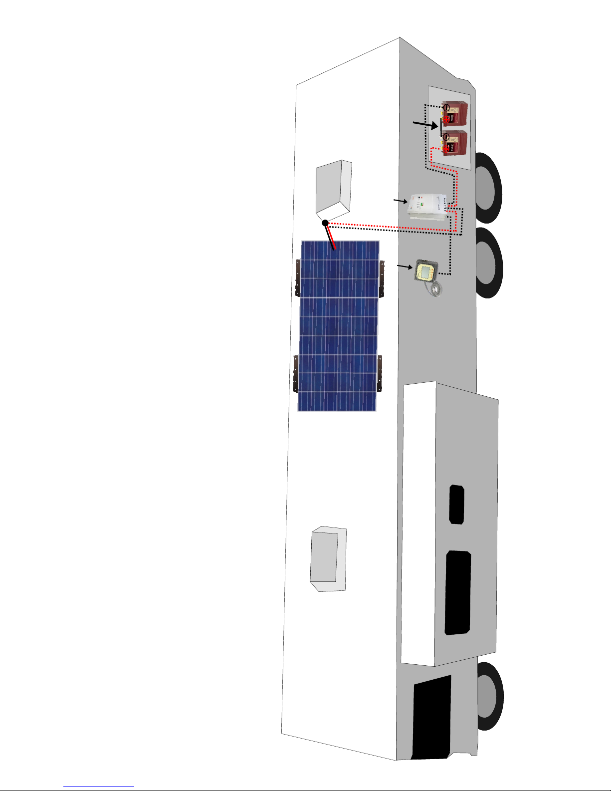
Charge Controller
Controller Meter
Wire Diagram of solar charging system
This setup is with an MPPT Charge controller and a Meter

RV Installation Guide
Solar Panels Solar Homes RV & Boat Kits
Manual Designed By: Jon Rotter
Table of contents


