MidNite Solar MNE250SMA User manual

SMA E-Panel installation manual
MidNite Solar Inc.
17722 –67th Ave Ne 360-403-7207 Voice
Arlington, Wa 98223 USA 360-691-6862 Fax www.midnitesolar.com
Model MNE250SMA
The MidNite Solar SMA E-Panel is designed for single & multiple inverter installations.
Use this installation manual to aid in installation. The installation of electrical systems such as this fall
under the guidelines of the NEC in the USA. Canadian electrical codes have jurisdiction in Canada.
These instructions are not intended to be used in lieu of these local and federal codes, but rather are
used as specific to this product. You may need to consult with a professional solar installer or electrical
inspector when in doubt on code specific questions and system installation issues. Even though the E-
Panel incorporates and simplifies numerous separate electrical circuits into one enclosure, an inverter
system such as this is still a very sophisticated and somewhat complicated electrical system.
Dual Master shown

SMA E-Panel installation manual
2 | P a g e 10-234- 1 R E V : A
This Manual contains information for MidNite Solar SMA E-Panel Model Numbers:
Masters:
MNE250SMA-AC SINGLE Single -
MNE250SMA-OG SINGLE Single –Off Grid
MNE250SMA-OG/AC DM Master –Dual Off Grid
MNE250SMA-QUAD MASTER Master –Quad System AC Coupled / Off Grid
MNE250SMA-3PH MASTER Master - 3 Phase
Slaves:
MNE250SMA-Slave Slave (right hand unit) for dual, 3PH and Quads
Backplates –Autoformer
MNESMA tall BP Back plate for AC coupled Master holds inv, E-Panel and autoformer
MNESMA short BP Short back plate for inverter and E-Panel
MNX-240 6000 watt autoformer for single inverter AC coupled system
Symbols used in this manual:
Caution: Indicates a condition where injury or damage may occur if instructions are not followed.
Danger: Indicates a condition where injury or death may occur if instructions are not followed.
Symboles utilisez dans ce manuel:
Attention: Indique un risque des blessures graves ou du dommage si on ne suit pas des instructions
dans ce manuel.
Danger: Indique un risque des blessures graves ou du mort si on ne suit pas des instructions dans ce
manuel.

SMA E-Panel installation manual
3 | P a g e 10-234- 1 R E V : A
IMPORTANT SAFETY INSTRUCTIONS
SAVE THESE INSTRUCTIONS- These instructions contain important safety and operating
instructions for the MidNite SMA E-Panel.
If you do not fully understand any of the concepts, terminology, or hazards outlined in these instructions, please refer installation to a
qualified dealer, electrician or installer. These instructions are not meant to be a complete explanation of a renewable energy system.
GENERAL PRECAUTIONS
If service or repair should become necessary, contact MidNite Solar Inc. Improper servicing may result in a risk of shock, fire or
explosion. To reduce these risks, disconnect all wiring before attempting any maintenance or cleaning. Turning off the inverter will
not reduce these risks. Solar modules produce power when exposed to light. When it is not possible to disconnect the power coming
from the Photovoltaics by an external means such as a combiner, cover the modules with an opaque material before servicing any
connected equipment.
Do not work alone. Someone should be in the range of your voice or close enough to come to your aid when you work with or near
Batteries.
Remove rings, bracelets, necklaces, watches etc. when working with photovoltaic modules or other electrical equipment. Power from
an illuminated photovoltaic array makes a very effective arc welder with dire consequences if one of the welded pieces is on your
person.
All installations must comply with national and local electrical codes. Professional installation is recommended.
Wiring must be done in accordance with the National Electrical Code ANSI/NFPA 70. Use Class 1 wiring methods
for field wiring connections to terminals of a Class 2 circuit. Use only 14-1/0 gauge AWM wire. Select the wire
gauge used based on the protection provided by the circuit breakers/fuses.
MidNite products are not intended for use in connection with Life Support Systems. MidNite Solar makes no
warranty or representation in connection with their products for such uses.
Disclaimer
Every effort is made to ensure the completeness and accuracy of all technical reference material, still,
unless specifically agreed to in writing, MidNite Solar Inc.
(a) Makes no warranty as to the accuracy, sufficiency or suitability of any technical or other information
provided in its manuals or other documentation.
(b) Assumes no responsibility or liability for loss or damage whether direct, indirect, consequential or
incidental, which might arise out of use of such information. The use of any such information will be
entirely at the user's risk.
If service or repair of the E-Panel should become necessary, contact MidNite Solar Inc. For other parts of
the system refer to the manual included with that equipment and contact the manufacturer for support.
Improper servicing may result in a risk of shock, fire or explosion. To reduce these risks, disconnect all
wiring before attempting any maintenance or cleaning. Turning off the inverter will not reduce these risks.
Solar modules produce power when exposed to light. When it is not possible to disconnect the power
coming from the Photovoltaics by an external means such as a combiner, cover the modules with an
opaque material before servicing any connected equipment.

SMA E-Panel installation manual
4 | P a g e 10-234- 1 R E V : A
INSTRUCTIONS DE SECURITÉ IMPORTANTES
CONSERVER CES INSTRUCTIONS
Ces instructions contiennent des informations importantes pour utiliser le Midnite Solar SMA MNX-
240 Autotransformer en toute sécurité.
1. Avant l’utilisez cet appareil lis et comprends toutes les instructions et avertissements.
2. Si vous ne comprenez pas l’une des concepts ou des instructions contenu dans cette manuel
consulter un agent spécialisé.
3. Si des réparations sont nécessaires contactez MidNite Solar pour plus des informations. Danger
de choc électrique et de risque de brulure. Rien à dépanner à l'intérieure du cette appareil. Ne
pas ouvrir le couver. Pour toute réparation ou service d'entretien, consulter un agent spécialisé.
Il y’a peut-être plusieurs sources d’alimentation dans cette system. Débrancher toutes les
interrupteurs avant toute d'entretien où nettoyage.
4. Ne travaillez pas seul. Quelqu'un devrait toujours être à proximité pour aider en cas d'une
situation d'urgence.
5. Retirer bagues, bracelets, colliers, montres, et quelles choses comme ça. Il y’a risque des
blessures graves s’il y’a un court-circuit. Cela pourrait ruiner votre journée entière.
6. Le câblage doit être fait en conformité avec le National Electrical Code ANSI / NFPA 70.
Utiliser des méthodes de câblage de catégorie 1 pour les connexions de câblage sur .des
terminaux d'un circuit de classe 2. Utilisez uniquement des fils de AWM de calibre 14-1/0.
Sélectionnez le type de câble utilisé sur la base de la protection prévue par les disjoncteurs /
fusibles.

SMA E-Panel installation manual
5 | P a g e 10-234- 1 R E V : A
Table of Contents
Model Number Descriptions................................................................................................................... 2
Warning Symbols.................................................................................................................................... 2
Warnings................................................................................................................................................3,4
Component locator...................................................................................................................................7
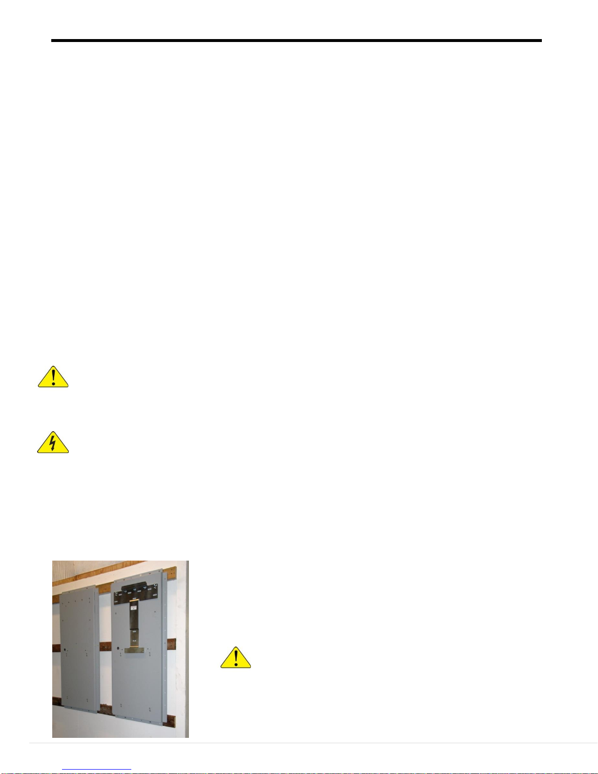
Mounting System to the wall...................................................................................................................8
Dimensional drawings............................................................................................................................13
Wiring......................................................................................................................................................15
Installing Conduit between E-Panels....................................................................................................16
AC Coupled Systems description..........................................................................................................19
Wiring Diagrams....................................................................................................................................20
Quad Master........................................................................................................................13, 23 , 24, 47
Single............................................................................................................................................19, 22, 44
AC Coupled Dual....................................................................................................................... 19, 27, 46
Off Grid Single............................................................................................................................20, 21, 44
Off Grid Dual....................................................................................................................................25, 26
Three Phase.......................................................................................................................................28, 29
Tightening torque for electrical connections .................................................................................30, 43
Classic Charge Controller with arc fault detection.............................................................................31
Charge Controller hookup ....................................................................................................................32
DCGFP Ground Fault............................................................................................................................34
Battery Combiner...................................................................................................................................35
Whiz Bang Jr..........................................................................................................................................36
MNX240 AutoFormer............................................................................................................................36
MNBE8D2x2 Battery enclosure............................................................................................................39
MNBDM Battery Disconnect Module ..................................................................................................40
MNBirdHouse Remote Shutoff.............................................................................................................41
New NEC Requirements........................................................................................................................42
Appendix. ................................................................................................................................................43
E-Panel descriptions...............................................................................................................................44
Slave unit.................................................................................................................................................49
Exchanging bus bars..............................................................................................................................50
Warranty.................................................................................................................................................52

SMA E-Panel installation manual
6 | P a g e 10-234- 1 R E V : A
All E-Panels:
4 9-565-1 1" Grommets
1 9-314-1 2" Grommet
9 6-032-1 1/4-20 Bolts 4 to mount the e-panel, 5 extra to mount the inverter
2 6-010-2 2 M6 Screws and other hardware for mounting inverter to backplate
1 10-234-1 Manual
Dual System:
8 9-565-1 1" Grommets
2 9-314-1 2" Grommet
18 6-032-1 1/4-20 Bolts 4 to mount the e-panel, 5 extra to mount the inverter
4 6-010-2 2 M6 Screws and other hardware for mounting inverter to backplate
2 9-489-1 10.5" Conduit
4 9-490-1 Conduit terminal adaptors
4 9-235-1 Conduit lock nuts
4 9-236-1 Conduit bushings
4 Additional connecting wires
1 10-234-1 Manual
Slave Unit:
4 9-565-1 1" Grommets
1 9-314-1 2" Grommet
9 6-032-1 1/4-20 Bolts 4 to mount the e-panel, 5 extra to mount the inverter
2 6-010-2 2 M6 Screws and other hardware for mounting inverter to backplate
4 5-015-1 Insulator, Black
4 5-015-6 Insulator, Blue
2 5-097-1 Insulator cover Black
4 6-037-1 Taptite screws
Units shipped with Classic:
1 3-013-1 Classic mounting bracket
3 6-029-1 Bracket mounting screw
1 6-058-1 Classic mounting screw
1 6-001-1 Classic mounting spacer
1 9-237-1 Conduit Nipple
Units shipped with 2 Classics:
2 3-013-1 Classic mounting bracket
6 6-029-1 Bracket mounting screw
2 6-058-1 Classic mounting screw
2 6-001-1 Classic mounting spacer
2 9-237-1 Conduit Nipple
3 Phase and quad Units:
2 Conduit sets for 3 phase
3 Conduit sets for quads
2 Required connecting wire sets for 3 phase
3 Required connecting wire sets for quads
Units shipped with a Battery Combiner:

SMA E-Panel installation manual
7 | P a g e 10-234- 1 R E V : A
DC Negative
500Amp/50mv
Shunt
Battery Plus Bus
MNSMARB
Relay board
Charge Controller
breakers*
PV
Positive and negative
input connections
Ground Busbar
AC Neutral busbar
AC Input
AC Output
under charge
controller breakers
Charge Controller
breakers*
DC Disconnect
Breaker –Relay
trippable
Bypass Breakers
Dinrail for
additional breakers
AC or DC
E-Panel Component location
Not all components installed on all models.
*If not used for the Classic these breaker
locations are available for extra load breakers.

SMA E-Panel installation manual
8 | P a g e 10-234- 1 R E V : A
Mounting the SMA E-Panel to the wall:
This section describes the general instructions for installing components to the wall or other mounting surface. When
you have completed this section then refer to the appropriate section for your model for specific instructions on
wiring and wiring diagrams.
Pre-Wired systems start on Page 13.
Note: The SMA E-Panel system should only be installed with the backplate. Failure to use the backplate can result in
poor alignment of system components resulting in a less reliable and non-code compliant installation.
Tools Required:
Long #2 Phillips Screwdriver
Medium slotted Screwdriver
Torque Screwdriver for electrical connections
9/16” Wrench
Large Allen wrench for inverter DC connections
Drill for pilot holes if required
Be sure to comply with all local and national code requirements including National Electrical Code, ANSI/NFPA 70.
Use Class 1 wiring methods for field wiring connections to terminals of a Class 2 circuit. Select the wire gauge used
based on the protection provided by the circuit breakers/fuses.
The SMA E-Panel is a type 1 enclosure suitable for installation in an indoor location protected from rain / snow etc.
When installing the system make sure to observe NEC maximum height requirements.
The system when complete will be quite heavy. Ensure that the wall can handle the weight of the system
and use appropriate fasteners. Have help when positioning and mounting system components to the wall.
Mise en garde! Cet appareil est assez lourd. S’assurer que le mur peut supporter le système. C’est nécessaire
d’avoir assistance pour installer le système.
High voltage is present throughout the system. Disconnect all sources of power and exercise extreme
caution when working with, on or around this equipment.
Attention: Il y a haute tension partout. Débrancher toutes les sources d’alimentation et faire attention autour
de le système. Lire aussi le manuel de l’inverter pour plus des informations.
Install the backplate either MNESMA tall BP or MNESMA short BP to the selected surface using a minimum of four
5/16 lag bolts with a minimum length of 2”.
The inverter should be installed before the E-Panel. Use ¼-20 bolts to attach the inverter mounting bracket, E-Panel
and MNX240 (if so equipped) to the backplate. The MNX240 requires the tall backplate.
Left: MNSMA Short BP Backplate
Typical backplate installation, shown mounted on wall with the inverter
mounting bracket installed (inverter mounting bracket supplied with
inverter).
CAUTION: The inverter is extremely heavy. Use extreme
caution when lifting the inverter. Refer to the inverter manual for
safe and proper inverter installation instructions. Make sure the
wall or other mounting surface can support the weight.
Encore, cet appareil est tellement lourd, sauvegarder vous-même.

SMA E-Panel installation manual
9 | P a g e 10-234- 1 R E V : A
Mounting the SMA E-Panel to the wall cont.:
Install the inverter mounting bracket before
mounting the backplate to the wall. Use ¼-
20 bolts and flat washers. Pressed in nuts
are provided on the backplate.
Ensure that the inverter bracket is centered
and is resting on the mounting screws
(down on the screws and not slid up).
Mounting on back of inverter
Inverter mounting bracket
mounted to backplate
Backplate mounted to wall
The inverter rests on the tab of the
inverter mounting bracket.
Caution!!
The inverter is veryheavy. Have
strong persons assist you.
Attention!!
L’inverter est très lourd. Avez des
gens très forts vous assister.
Secure inverter to bracket with the
M6x10 screws provided.
Left and right sides.
Cover with fan grills provided.
The grills are marked left and
right.

SMA E-Panel installation manual
10 | P a g e 10-234- 1 R E V : A
Mounting the SMA E-Panel to the wall cont.:
Inverter lower mounting screw locations.
The inverter is spaced away from
the back plate at the four lower
mounting screws.
These two mounting locations are not used
Inverter lower mounting screws installed

SMA E-Panel installation manual
11 | P a g e 10-234- 1 R E V : A
Mounting the SMA E-Panel to the wall cont.:
E-Panel mounting holes
E-Panel mounting holes.
Place the E-Panel below the inverter and line up the E-Panel mounting holes with the holes in the backplate.
Attach the E-Panel to the backplate with ¼-20 bolts. Pressed in nuts are provided on the backplate.
Remove the deadfront
(metal front cover) by
removing the screws in the
four corners and the two
on the DC disconnect
breaker.
When reinstalling the
deadfront ensure that the
breaker handles are
protruding through the
slider as shown.
Slider

SMA E-Panel installation manual
12 | P a g e 10-234- 1 R E V : A
Attaching the Autoformer –Required for AC coupling of a single Sunny Island inverter.
The tall backplate is required when using the MNX240 AutoFormer.
The optional 6000 Watt Autoformer for single inverter AC Coupled systems mounts above the inverter.
Position the MNX240 Autoformer above the inverter and line up the mounting holes. Install with ¼-20
hardware.
Plastic cover installation:
To install the cover line up both molded in hinge pins
with the cover mounting brackets and slide down into
position.
Hinge Pin
Cover mounting bracket on E-Panel
Hinge pin installed into mounting bracket
MNX240 Autotransformer
Shutoff / Circuit Breakers
Hookup terminal blocks
Hot
Neutral

SMA E-Panel installation manual
13 | P a g e 10-234- 1 R E V : A
Mounting the SMA E-Panel to the wall continued:
Above: Quad system with Battery Combiner.
Studs are shown for reference and are at 16” centers.
If mounting on plywood use ¾” material.
Use a minimum of eight 1/4” screws per backplate.
Pre-Wired Systems: Systems are available pre-assembled / pre-wired. It is not necessary to disassemble
systems to mount them on the wall. One way to install a pre-Wired system is to find where the bottom of the
backplate will be when installed and securely screw a 2x4 to the wall with the top just at where the backplate
will be. Place the bottom of the backplate on the 2x4 and have two people tip it up into place and secure the
backplate to the wall with a minimum of 8 ¼” screws at least 2” long.
Left Side knockout location
Front
Top
2/0 Battery cable lengths necessary to complete
installation as shown above:
E-Panel
Positive
Negative
#1
71”
71”
#2
45”
41”
#3
30”
44”
#4
60”
75”

SMA E-Panel installation manual
14 | P a g e 10-234- 1 R E V : A
Bottom knockout location
Right Side knockout location
Front
Top

SMA E-Panel installation manual
15 | P a g e 10-234- 1 R E V : A
System wiring
The SMA E-Panel is a complex system and should be wired by a qualified electrician.
Danger: Hazardous voltages are present throughout the system. All power must be removed
before attempting any wiring or maintenance of the system.
Danger: Il y a haute tension partout dans le système entière. Débrancher toutes les sources
d’alimentation avant faisant des connections ou l’entretien.
The following pages contain wiring diagrams for many configurations. Follow the appropriate one for
your installation such as on or off grid, AC Coupled or three phase. The diagrams below also cover
single, dual and quad systems with up to 7 Classic Charge Controllers. Components sold separately.
If you are unsure of any aspect of the installation contact a licensed electrician or MidNite Solar at
360.403.7207.
DC Wiring:
If using the optional Battery Combiner run 4/0 wire from the battery breaker to the positive connection
in the Battery Combiner and 4/0 wire from the E-Panel shunt. It is acceptable to use black wire if the
ends are clearly marked red or white as appropriate. Use copper wire of adequate gauge (Determined by
breaker size) rated for a minimum of 75°C. Always use approved conduit and fittings.
Use 4/0 wire for a 250 Amp battery breaker and 2/0 for a 175 Amp battery breaker.
Negative connections to inverters
Positive connections to inverters
Negative shunt connection
To batteries
For installations not using the Battery Combiner connect a positive wire from the E-Panel breaker to the
battery bank positive and a negative wire from the E-Panel shunt. These wires should be kept as short as
possible. Running the wires close together will reduce ripple currents.
AC Wiring:
This varies greatly depending on your system configuration. The following wiring diagrams show on and off
grid, with and without a generator, AC coupled and three phase systems. Please pay special attention to the
information on AC coupled systems. Use appropriate conduit and fittings for a safe, reliable, code compliant
system.
Slave units are shipped with red mounting blocks and covers for AC in and AC out installed. Black and blue
mounting blocks and covers are included. Should you desire to change the mounting blocks and covers to
match the desired wire color (L1 Black, L2 Red and L3 Blue) Simply pull the cover off, press the retaining
tab on the mounting block to release the terminal block and remove the terminal block. There is a Phillips
screw in each mounting block. Remove and retain the screw. Using the new color reverse the process to
reinstall. Note: Use caution when tightening the screws. The chassis can be stripped if the screws are over-
tightened. Should this occur the use a slightly longer #10 screw and a #10 nut from behind.
Positive connections to batteries

SMA E-Panel installation manual
16 | P a g e 10-234- 1 R E V : A
INSTALLING CONDUIT BETWEEN E-PANELS:
Bushing
Nut
Fitting
Conduit
Fitting
Nut
Bushing
Conduit and fitting parts
With one inverter installed, remove the top
and bottom knockouts (see image next page)
that face the other E-Panel and push one of
the fittings from the outside through the
knockout opening into the E-Panel.
Inside the E-Panel, secure the fitting with
one of the nuts and a bushing
These instructions are for installing the supplied conduits and fittings in a system with a Battery
Combiner.

SMA E-Panel installation manual
17 | P a g e 10-234- 1 R E V : A
Place a fitting on one side of a conduit
and insert the other end of the conduit
into one of the fittings installed in the
previous step.
Remove the facing knockouts on the
second inverter. Move the second E-Panel
into place. Secure the E-Panel to the wall
then, secure the conduits with a nut and
bushing.
Make sure to use the bushing. It is there
to protect the wiring.
Conduit installed and ready for wiring
Knockouts
Removed

SMA E-Panel installation manual
18 | P a g e 10-234- 1 R E V : A
Typical wire routing between E-Panels.
Refer to the appropriate wiring diagram for your system.
In the example above L2OUT goes from the transfer breakers on the master to the L2OUT busbar on the
slave unit, L2IN goes from the L2IN busbar on the master unit to the L2IN busbar on the Slave unit, all
in the lower conduit. The ground can be in either conduit as is convenient. The inverter communication
cable is routed through the upper conduit.
*Ground wire may be routed through either conduit.
Power and communication wiring should be kept separate.
Installing conduit between Inverters continued.

SMA E-Panel installation manual
19 | P a g e 10-234- 1 R E V : A
AC Coupled Systems.
AC coupling allows a grid-tie system to also provide backup power during an outage. Grid tied systems are
required to stop sending power to the grid immediately upon a power failure. This is for the safety of the
linespersons effecting repairs as well as others who may encounter downed lines. Most inverters shut down
completely at this point leaving you in the dark while your array or turbine are producing unused power.
In an AC Coupled system when the power fails the inverter is disconnected from the grid but continues to
supply power to the critical loads panel. The array or turbine continue to send their power to the batteries
for charging or running loads. The SMA Inverter used in this system is particularly adept at this form of
coupling giving you the best of both worlds of grid-tie and power backup.
Generator hookup to a standalone system vs. an AC coupled system.
Off Grid the generator goes to the AC input on the inverter.
Utility connected non grid tie system the generator and inverter go to a switch (Not included) so that the
inverter is fed by the grid or the generator. This may be automatically or manually switched depending on
the system.
Off Grid the generator goes to the AC input on the inverter.
Utility connected non grid tie system the generator and inverter go to a switch (Not included) so that the
inverter is fed by the grid or the generator. This may be automatically or manually switched depending on
the system.
AC coupled grid tied single system the generator then goes through the normally open contacts of a relay
(sold separately) and then to the inverter.
Inverter wiring and wiring between E-Panels complete. Ready for AC/DC in and out connections.
Master
unit
Slave
unit

SMA E-Panel installation manual
20 | P a g e 10-234- 1 R E V : A
SMA SUNNY ISLAND OFF GRID SYSTEM
WITH SINGLE CLASSIC CHARGE CONTROLLER
DRAWN BY T.
CARPENTER
2/05/13
L1 OUT
L1 IN
NEUTRAL
NEUTRAL
NEUTRAL
SUNNY
ISLAND
GROUND
HOT OUT
HOT IN
250
ON
OFF
ON
OFF
60
A
GROUND
BATTERY
NEGATIVE
BATTERY
POSITIVE
+-
GROUND
ON
OFF
60
A
AC INPUT
AC OUTPUT
ON
OFF
ON
OFF
6060
ON
OFF
ON
OFF
60 60
ON
OFF
ON
OFF
ON
OFF
ON
OFF
ON
OFF
ON
OFF
ON
OFF
ON
OFF
ON
OFF
ON
OFF
ON
OFF
ON
OFF
ON
OFF
ON
OFF
ON
OFF
LOADS
120 V
NORMAL
BYPASS
SPD
300
6V
400ah
6V
400ah
6V
400ah
6V
400ah
6V
400ah
6V
400ah
6V
400ah
6V
400ah
6V
400ah
BATTERY 48 V
GENERATOR
POWER SOURCE
NOTE: GROUND CONNNECTIONS
TO EXTERNAL PANELS HAVE BEEN
OMITTED FOR CLARITY
THESE MUST OF COURSE BE
INSTALLED IN THE FIELD
BATTERY
PLUS BUS
ON
70
ON
ON
90
PV PLUS BUS
CLASSIC 150
PV INPUT AND
CLASSIC OUTPUT
BREAKERS
LOCATED ON SIDE
OF E-PANEL
PV ARRAY
SPD
300
Typical complete off grid system with one MNE250SMA-OG and one Classic charge controller.
Parts sold separately.
Table of contents
Popular Solar Panel manuals by other brands

Anslut
Anslut 014400 operating instructions

Schüco
Schüco MSE 210 installation instructions

Schweizer
Schweizer Solrif Quick installation guide

DÖRR
DÖRR SP-1500 instruction manual

DeDietrich
DeDietrich POWER SUN 3000 Instructions for Roof-Surface / Flat Roof Installation

Regulus
Regulus KPC1 BP Installation and operation manual

Phaesun
Phaesun Solar Modul Ascent 45W Safety and installation manual

Viessmann
Viessmann Vitosol 222-T Operating Instructions for the System User

Creabest
Creabest GSM-120W manual

Yalp
Yalp SOLAR installation instructions

SOMFY
SOMFY Solar Pack installation instructions

rollease acmeda
rollease acmeda AUTOMATE Solar Panel 2.0 manual