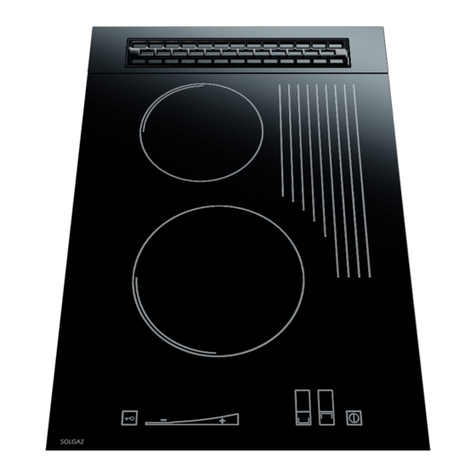
Solgaz GNC-4 User guide

Sp. z o.o.
solgaz.eu
Assembly and instruction manual for
GAS CERAMIC HOB
to be built-in
GNC - 4
WARNING!
For your safety, please read the notes and suggestions presented further in this instruction
manual.

2
The gas hob can be connected to the gas source only by an installer
with qualifications to work with gas appliances.
This device is not to be connected to exhaust pipes.
The device should be installed and connected in accordance with applicable legal
regulations.
Warning!
If the hob's glass plate breaks, stop using it immediately
and contact the service department.
Please also be careful when handling the hob:
- do not touch, do not move metal grates or burner components
during use or immediately after. This can cause burns.
- do not place metal grids on the glass outside of their designated place (near the
burner). Grate assembly components can scratch the glass plate of the hob.
We guarantee the correct operation of the purchased gas hob.
However, if there are any problems related to the use of the device, our Support Department
will provide you with fast and professional help. We want to guarantee all those who have
trusted us full comfort in everyday use
of our product.
This device is labelled in accordance with European Directive 2002/96/EC on used electrical
and electronic equipment. After its period of use, the device cannot be thrown away with
other household waste. The user is required to return it to an entity engaged in the collection
of waste electrical and electronic equipment.
DEAR SIR OR MADAM

3
Thank you for your trust and purchase of the Solgaz automatic gas hob.
Our technology is sure to inspire you to better cooking each day thanks to the
hob's aesthetics, convenience and safety.
Sincerely,
SOLGAZ
TABLE OF CONTENTS:
1. GENERAL INFORMATION AND SAFETY INSTRUCTIONS............................................................................4
1.1. PURPOSE OF THE DEVICE............................................................................................................................. 4
1.2. TECHNICAL SPECIFICATIONS OF THE HOB ........................................................................................................ 4
1.3. HOB CONSTRUCTION.................................................................................................................................. 5
2. REQUIREMENTS FOR HOB INSTALLATION ............................................................................................... 6
2.1. REQUIREMENTS FOR ROOMS ....................................................................................................................... 6
2.2. INSTALLATION OF THE HOB IN A KITCHEN CABINET COUNTERTOP ......................................................................... 7
2.3. GAS SYSTEM............................................................................................................................................. 8
2.4. ELECTRICAL SYSTEM................................................................................................................................... 9
3. TIPS FOR THE INSTALLER ......................................................................................................................... 9
3.1. GENERAL INFORMATION............................................................................................................................. 9
3.2. Adapting the hob to another type of gas ........................................................................................ 9
3.3. Maintenance and inspections of hob elements............................................................................. 10
4. USING THE HOB..................................................................................................................................... 10
4.1. INITIAL ACTIVITIES ................................................................................................................................... 10
4.2 HOB CONTROL PANEL ................................................................................................................................... 11
4.3. STARTING THE HOB.................................................................................................................................. 11
4.4. WORK PROGRAMMES AND HOB FUNCTIONS ................................................................................................. 11
4.4.1. Residual heat indicator.................................................................................................................. 12
4.4.2. Standard operating mode ............................................................................................................. 12
4.4.3. Water boiling function................................................................................................................... 12
4.4.4. Flame size stabilisation function ................................................................................................... 13
4.4.5. Booster function ............................................................................................................................ 13
4.4.6. Timer function ............................................................................................................................... 14
4.4.7. Pause function –Stop'n go ............................................................................................................ 14
4.4.8. Turning the controller lock on and off ........................................................................................... 15
4.5. SELECTION OF POTS AND PANS................................................................................................................... 15
5. HOB CLEANING AND MAINTENANCE..................................................................................................... 15
5.1. REGULAR CLEANING................................................................................................................................. 16
5.2. INSPECTION AND SUPERVISION OVER GAS,ELECTRICAL AND VENTILATION SYSTEMS. ............................................. 16
6. PROCEDURE IN CASE OF FAILURES, ERROR SIGNALS ............................................................................. 17
7. WARRANTY CARD FOR THE GNC-4 GAS CERAMIC HOB ......................................................................... 19

4
1. GENERAL INFORMATION AND SAFETY INSTRUCTIONS
1.1. Purpose of the device
GNC type hobs are hobs for in-built installation, designed for preparation of dishes
and use in households. The gas burners are equipped
with temperature sensors, which assure maximum user safety and automatic, precise
operations. GNC belongs to a generation of gas hobs, whose burners are controlled
electronically and the device has
sensor-based control. The hob is designed for in-built installation in the countertop of a
single kitchen cabinet or in a composite countertop.
1.2. Technical specifications of the hob
Parameter
Unit
Value
Type and group of supplied
gas
2E
2Lw
2Ls
2L
3B/P
3P
3P
G20
G27
G2,350
G25
G30
G31
G31
Nominal connection
pressures
mbar
20
20
13
25
37
37
30
Thermal power of all 4
burners
kW
7.4
Gas stream of all 4 burners
g/h
~740
(This value applies only to liquefied gases)
Power of individual burners
Large burner
kW
2.8
Nozzle diameter
mm
1.31
1.49
1.90
1.35
0.85
0.90
0.90
Medium burners
kW
1.8
Nozzle diameter
mm
1.05
1.25
1.49
1.05
0.70
0.75
0.79
Small burner
kW
1.0
Nozzle diameter
mm
0.79
0.90
1.05
0.85
0.50
0.55
0.57
Gas connection
on the underside of the hob with an R1/2 internal pipe thread
Voltage and power supply
230 V/50 Hz -12V DC 4.5 A 60 VA
Protection rating
IP40
Device class
II
Hob dimensions
(W x D x H)
mm
580 x 500 x 67 (the dimensions include the protruding cover for
engines), grid above the hob - 55
WARNING!
Please bear in mind that stepper motors placed under the hob's glass plate control the size of
the flame and may be audible during adjustments. When the burner is turned on and the gas
ignited, a regular sound (knocking) can be heard. These are normal phenomena
and sounds of a working hob.

5
1.3. Hob construction
The ceramic plate (Fig. 1) features 4 special open gas burners,
of which the 3 largest are equipped with temperature sensors. Burner operations are controlled
electrically via a stepper motor. Built-in temperature sensors allow you to program a
constant cooking temperature, boil water and protect the burner from working without a
pot or pan.
The control units are powered with 12 V DC provided through a power supply from a 230 V
mains supply. The power supply is provided as a set with the purchased hob.
It is also possible to purchase an additional auxiliary power supply that allows the hob to
work in the absence of mains electricity. This is available on special order.
Gas can be sourced from the gas transmission system or a cylinder with liquefied gas.
The front part of the hob features a touch control panel. It enables control and monitoring
of individual burners and selection of operating modes.
Fig. 1 GNC hob
1 –ceramic glass plate, 2 –control panel, 3, 4, 5, 6 –cast iron grates for burners,
7, 8, 9, 10 –burner rings, 11, 12, 13, 14 –burner caps,
15, 16, 17, 18 –ignition electrode, 19, 20, 21 –thermal electrode (temperature sensor)

6
Fig. 2 Side view (from the right) of the GNC hob
1 –thermal electrode (temperature sensor), 2 –cast iron grates for burners, 3 –burner caps,
4–ignition electrode, 5 –burner body,
6 –burner ring, 7–hub body
2. REQUIREMENTS FOR HOB INSTALLATION
All activities related to the assembly and connection of the hob to the gas
and electrical distribution systems must be performed by a licensed installer qualified to
work with gas.
Warning:
Before installing and connecting the gas hob, check whether the hob is suited for the
type of gas that is to be used and whether it is compatible with the type of gas indicated on
the name plate of the hob. In case of incompatibility, do not perform assembly.
Warning:
The hob can be adapted to a different type of gas only by a licensed installer
qualified to work with gas. If in doubt about the type of gas supplied through your gas
distribution network, please contact the local gas distributor.
2.1. Requirements for rooms
Rooms in which the hobs are installed should be dry and airy, and offer efficient
natural ventilation due to the emission of exhaust fumes and heat. Assure good ventilation
of the kitchen, keep open natural ventilation openings or install mechanical ventilation
equipment (hood with mechanical removal).
Prolonged, intense use of the device may require additional ventilation: opening
windows or more effective ventilation, e.g. increasing the efficiency of mechanical
ventilation, if such is used.
The legal basis for determining the suitability of a room
in a building for installation of a gas hob is the Regulation of the Minister of Infrastructure on
the technical conditions that should be met by buildings and their location. (Journal of Laws
No. 75 as of 12.04.2002 Chapter 7, as amended.)
If a range hood is installed above the hob, the minimum distance between the
ceramic glass plate and the hood should not be less than 600 mm. We recommend a

7
distance of
750 mm.
The hob is not adapted for connecting to exhaust gas pipes. It should be installed and
connected in a manner compliant with current installation regulations.
2.2. Installation of the hob in a kitchen cabinet countertop
The countertop, in which the gas hob is installed must be screwed in permanently to
the cabinets or permanently connected with other furniture elements. In order to install the
hob in the countertop of a kitchen cabinet or a composite countertop, prepare a 540 x 480
mm opening. If the hob is installed above an oven, the opening for the hob should be made
symmetrically.
When the hob is installed next to cabinets standing on the countertop or in a corner
between walls, maintain a distance of at least 150 mm from the side of the cabinet or wall
corner.
The hob is fixed to the countertop using a self-adhesive gasket. We do not
recommend a different fixing method, using silicone in particular.
We recommend removing the rear wall of the cabinet in order to ensure better
ventilation under the hob. This also applies to installations with an oven.
A partition below the base of the hob is not required.
Fig. 3 GNC hob dimensions
Fig. 4 Installing the hob without an oven
1–Ventilation opening under the countertop: 2 –Air intake grille

8
Fig. 5 Installing the hob over an oven
1–ventilation opening in the lower shelf; 2–free space between the shelf and the back of the cabinet (air
flow); 3 –ventilation opening under the countertop
2.3. Gas system
The GNC –4 gas hob has a vertical connection terminated with an internal R ½"
thread (ISO 7-R1/2). It is recommended to connect the hob to the gas distribution system by
means of a flexible hose with a safety certificate.
The system used for supplying the hob from the gas distribution system should be
equipped with a cut-off valve.
The gas hob uses a mesh gas filter, which is responsible for capturing and removing
mechanical impurities. It assures appropriate flow in the system
and efficient operation. No maintenance or cleaning is required.
If the hob is supplied with liquefied gas from a gas cylinder, connect it using a
ø10/R1/2" connector screwed onto the gas inlet. On the cylinder valve, install a regulator for
liquefied gases. Connect the regulator with the hob using a flexible hose suitable for
liquefied gases (with a maximum length up to 3 m) with bands attached at both ends.
The regulator and flexible hose must have a safety certificate.
It is the user's responsibility to replace fittings
with a limited period of use.
The gas connection should be routed in such a way that there are no bends
with a radius smaller than 150 mm and that it does not come into contact with heated
elements of the hob's housing and other devices (e.g. oven).
The flexible hose that supplies the hob should be mounted in such a way that it does
not touch the moving parts of the housing section (e.g. drawer) and does not pass through a
space with insufficient dimensions.
For reasons of user safety, installation of the hob must be performed by a gas
appliance installer!

9
Please note:
Laws in force in Poland prohibit the connection of gas appliances to LPG cylinders in
buildings with a gas distribution system
(Journal of Laws No. 75 Chapter 7).
2.4. Electrical system
In order to ensure correct and safe use of the hob, an electrical power supply (230
V/50 Hz) needs to be run to the vicinity of the hob for connecting the power supply unit.
The electrical socket should be equipped with a protective pin and cannot be placed
directly above the hob or at a distance smaller than 10 cm from the side of the hob and at
least 10 cm above the upper plane of the hob, and absolutely outside the area where hot
exhaust gases flow out of the burners. A properly ventilated space needs to be provided for
the power supply unit.
The power supply cable from the mains electrical system and the power cable to the
hob should be run in such a way that they do not come into contact with heated parts of the
hob or heat generating devices installed beneath.
3. TIPS FOR THE INSTALLER
3.1. General information
Only a trained and authorised installer may perform activities related to assembly,
connection of the hob to the gas
and electrical distribution systems, and adjusting the burners to another type of gas.
Before proceeding to the assembly and connection of the hob to the gas and electric
systems, the installer should check that:
- the room, in which the hob will be used, meets the requirements of current
regulations (volume, dimensions, hob location),
- the gas and electric systems are made in accordance with applicable standards
and regulations.
The employee performing the installation must, after completing all activities,
confirm their performance (list of activities, date, signature and company stamp) in the
hob's warranty card, which is the basis for the warranty and statutory warranty of the
purchased hob. Otherwise, the warranty card is invalid.
After installation, the installer must perform the first start-up. At the first start-up
of the hob, the burner may ignite after a longer time. This is a normal phenomenon, caused
by gas filling the pipes and the burner itself. This disappears after the first start-up.
3.2. Adapting the hob to another type of gas
If it is necessary to adapt the hob to a different type of gas than the one for which it
was prepared by the manufacturer at the factory, all gas nozzles in burners need to be
replaced with such appropriate for the particular gas (in accordance with data in the table in

10
point 1.2).
It is also necessary to replace the hob's solenoid assembly and modify the controller
software. This procedure can only be performed by an authorised service centre.
3.3. Maintenance and inspections of hob elements
When operated in accordance with this instruction manual, and cleaned
and maintained, a properly working hob does not require inspections.
4. USING THE HOB
4.1. Initial activities
After installing the hob in accordance with point 2.:
- place the burner body (item 5, fig. 2) in the hob's body (item 7, fig. 2) paying
attention that it is evenly (horizontally) placed,
- place the burner cap (item 3, Fig. 2) centrally on the burner ring; be careful when
placing caps on burners with a temperature sensor (item 1, Fig. 2),
- place grids (item 2, Fig. 2) on the hob's glass plate, making sure that the metal pins
fit the openings in the glass,
- insert the plug of the power supply cable into the mains power socket
and place the 12 V low voltage cable ended with a circular plug in the power socket of the
hob (it is located on the bottom of the device, in the lower right corner, under the control
panel),
- open the cut-off valve on the gas supply line to the hob,
- once connected to electrical power, the hob will start its calibration mode. The
timer section of the display will show "00" and horizontal signs will appear above the
burners' sensors. Once the markings above the sensor of the upper right burner disappear, a
blinking calibration symbol will appear. When this disappears, the hob enters standby mode
and is ready for use. This is signalled by an indicator light (item 1, Fig. 6). Stepper motors can
be heard during calibration (knocking).
When the hob is used for the first time, open a window and assure air access to the
room. This will ensure better air exchange in the kitchen, allowing unpleasant odours to
escape.

11
4.2 Hob control panel
Fig. 6 Control panel –item 2. from Figure 1.
1–switch indicator, 2 –lock indicator, 3 –hob on/off switch,
4–hob panel lock, 5,6,7,8–digital indicators of the set burner power,
9–timer indicator, 10, 11, 12, 13 –burner selection fields, 14 –increasing power,
15 –reducing power, 16 –timer switch, 17 –booster function switch,
18 –boiling function switch, 19 –stop'n go function on/off switch, 20 –power level stabiliser function switch
4.3. Starting the hob
To start the hob, after completing the initial steps from point 4.1., touch the main
sensor switch (item 3, Fig. 6) with your finger. The switch indicator goes out (item 1, Fig. 6)
and the hob is ready to accept commands. All four field indicators (item 5, 6, 7, 8 in Fig. 6)
show "0000" for 6 seconds. If no further action is taken, after that time the hob goes into
standby and indicators turn off, with only the switch sensor remaining lit. The switch can be
used to turn off the hob at any time, even with the lock activated.
4.4. Work programmes and hob functions
The GNC hob can work in different modes, which allow comfortable, precise and safe
cooking. All changes in the way burners work are introduced through the control panel. The
size of the flame and the power output of the burners are controlled automatically.
The hob will turn off automatically after 4 hours of operation without any changes of
settings, if there are pots or pans on the burners. In case there are no pots or pans on the
medium or large burners, it will switch off when the safety temperature limit is reached,
which is lower than the self-ignition temperature of edible oil. This is aimed at protecting
the hob's components from overheating and ensuring user safety.
The smallest burner is not equipped with a temperature sensor. The set temperature and
boiling functions are not available in its case.

12
This burner will not turn off, if there are no pots or pans, however, the other burners will.
Please pay special attention to this.
Descriptions for starting and using each of the available work modes are shown
below:
4.4.1. Residual heat indicator
When a burner is turned off, its elements and the grate remain hot. To protect the
user against accidental burns, an "H" is displayed over the sensor of the turned off burner.
Only once it turns off is it safe to touch elements of the burner, grates and glass in this area.
4.4.2. Standard operating mode
A specific, constant power/flame size can be set for each of the burners.
After a burner is selected using its sensor (items 10, 11, 12, 13), use the + and –
sensors (items 14, 15) to choose power on a scale from 1 to 9, where each level contains 3
adjustment levels. This allows precise adjustments, with a total of 25 different flame sizes.
Burner power is pre-set to 5 to facilitate quick selection of more or less power.
Holding the + or - sensor can speed up the adjustment, as it then jumps a full level (3
levels of adjustment simultaneously).
The burner is turned off by a double tap on the corresponding sensor.
Despite setting the same power level on the two medium-sized burners, the flame
sizes may differ slightly. This does not indicate incorrect operation of the hob, as this
phenomenon results from the independent construction of both burners.
4.4.3. Water boiling function
This programme makes it possible to automatically boil water and turn off the burner
once finished.
For the function to work properly, please follow the instructions below:
- use a kettle/vessel with a lid, a thin bottom and 0.5 l to 3 l capacity,
- the water should be at room temperature when the programme is switched on,
- do not interrupt the programme,
- do not add or pour out water.
Pay attention and maintain the above parameters because a change or interruption of the
programme (e.g. using the stop'n go function) can reduce the precision and boiling time.
The boiling mode is started by selecting the burner using the appropriate sensor
(items 10, 12, 13) and touching the programme sensor (item 18). Medium burners start at
level 9, the large burner at 5, with field indicators (items 5, 7, 8) displaying horizontal lines
rising from the bottom up. The hob uses temperature sensors to automatically cut off the
gas supply after the water boils. The programme allows it to boil for a short time to ensure
that the water is cooked and sterilised. The boiling time is also dependent on the material
parameters of the pot or pan, altitude A S L, ambient temperature and type of gas used.
To turn off the boiling function, touch the sensor field of the burner (items 10, 12, 13)
used in this mode and after selecting, touch the boiling mode sensor (item 18). The burner

13
will return to continuous operation in manual mode.
A burner with the boiling programme activated cannot use the timer, booster and
flame size stabilisation modes. You can use the stop'n go (pause) function, but this may
disrupt the programme, as per the above. You can also use the control panel lock function.
4.4.4. Flame size stabilisation function
This function allows you to maintain the set power level for the prepared dish (range:
from 40 to 220. This gives a total of 181 settings). Power levels indicate the temperature, but
due to the properties of various vessels, the type of gas, ambient temperature, food density,
etc., the obtained results may differ from the actual temperatures in the pot or pan. The
flame's power is automatically
and smoothly maintained at one level by stepper motors.
The function applies only to burners equipped with a temperature sensor.
If the temperature increases too quickly or exceeds the set safety threshold, the flame is
reduced or even extinguished. In case of the temperature being too low in relation to the set
power, the hob automatically increases the flame.
The mode is started by activating a given burner with its sensor (items 10, 12, 13) and
touching the function sensor (item 20).
The digital display (item 9) will show a power indication symbolising the temperature,
which the hob will aim to achieve. The value is raised or lowered by means of the +and –
sensors (items 14, 15).
After 6 seconds, the temperature indicator will be switched off and a small letter "c"
will appear on the indicator field of the burner, for which the function is activated.
In the event of a change in power level, the flame size is adjusted in real time.
To exit the power level stabilisation function, touch the sensor for the field (items 10,
12, 13), for which the function is activated and touch the function sensor (item 20).
After switching off the function or after an exit, the hob will set the burner output to the one
used currently in stabilisation mode.
4.4.5. Booster function
This function allows immediate and automatic setting of the selected burner's
maximum power. It can be used when the power level stabilisation programme is activated
and the burner is working as standard. The function does not work in the water boiling
mode.
To use the function, touch the sensor of any working burner
(items 10, 11, 12, 13) and then the booster function sensor (item 17). At this moment, the
hob will set the maximum power on the burner for 3 minutes. The display for the burner
using the booster function will be marked with the letter "P" and a dot in the lower right
corner of the burner display (items 5, 6, 7, 8).
The function can be switched off before the lapse of 3 minutes by changing the

14
programme on a given burner or by touching the booster function sensor (item 17) for the
selected burner.
4.4.6. Timer function
The programme allows automatic shutdown of the hob. The working time can be set
within a range from 1 to 99 minutes.
The programmes work on every selected cooking zone and are independent of each
other.
When the timer is working, changes can be made to the hob's work mode.
Completion of the timer programme is signalled with a visual (the power level of the
turned off burner will start to flash) and audio signal.
Once switched off, the message "H" remains.
To take advantage of the function, touch the sensor of any working burner (items 10,
11, 12, 13, Fig. 6)and then the timer function sensor (item 16, Fig. 6).
Above the row of burner power displays (items 5, 6, 7, 8, Fig. 6) a function display will
appear (item 9, Fig. 6), which will show "00". In 6 seconds, set a time in minutes using the +
and - sensors (items 14 and 15, Fig. 6) within a range from 1 to 99. After this time the burner
will be turned off. When the timer function is on, the burner display will be marked with a
blinking dot in the lower right corner of the display (items 5, 6, 7, 8).
You can see the time remaining in minutes until the the burner is turned off and
change this value at any moment. To check the remaining time/make a change, touch the
burner sensor with the active timer function (items 10, 11, 12, 13) and then the timer
function sensor (item 16). The timer display (item 9) will show the remaining time set until
the burner is turned off.
The function can be switched off by changing the work programme or turning off the given
burner. You can also activate the timer function by setting the working time and then
the work programme when starting the hob.
4.4.7. Pause function –Stop'n go
The pause function can be used at any time during cooking. It allows you to stop the hob and
later return, with the previously set programmes and heating levels.
At least one burner of the hob must be working. When you touch the pause sensor
(item 19, Fig. 6) markings will light up in the indicator locations and the operation of the
hob will be suspended for up to 15 minutes for all cooking zones. When the pause function is
on, it is only possible to use control panel lock sensors (item 4, Fig. 6)
and on/off sensors of the hob (item 3, Fig. 6)
The pause function is turned off by touching the function sensor (item 19, Fig. 6). At
that moment the indicators of previous settings will light up again and the hob will continue
to operate.
If the function is not switched off after 15 minutes from its activation, the hob will
turn off.

15
4.4.8. Turning the controller lock on and off
The controller lock protects the hob against accidental starting or a change in the
power of the working burners.
In order to prevent uncontrolled starts, switching off or changing the burner's power, use
the controller lock, which is done as follows:
Touch the sensor (key) with your finger item 4 Fig. 6. Pressing and holding it for 5
seconds will cause the controller to lock, the indicator diode to switch on and an extended
audio signal to sound.
To unblock the hob controller, follow a similar procedure:
Touch the sensor with your finger item 4 Fig. 6 and hold for 5 seconds, the indicator
diode item 2 Fig. 6 switches off, the hob controller is unlocked and an audio signal can be
heard.
4.5. Selection of pots and pans
To ensure optimum use of the heat generated by the flame from the gas burner, use
appropriate pots and pans. They must have:
- a flat bottom,
- a bottom diameter larger than the diameter of the burner.
In addition, the pots and pans are to be covered with lids (if permitted by the recipe).
Also ensure that the lid does not protrude beyond the cookware, so that condensate does
not drip onto the glass plate of the hob. This way, you will avoid difficult to remove stains.
Do not use such cookware on the hob that extends significantly beyond the heating
area edges. In addition, the diameters of the bottom of the pots and pans placed on the
large and small burners
at the front of the hob, should not exceed 22 cm. Failure to comply with this may cause the
control panel to overheat and increase the risk of burns to the user.
Cookware should be placed centrally on the grate above the centre of the burner
before it is switched on. The minimum diameter of the cookware should not be smaller than
the diameter of the flame crown of a particular burner.
Pay special attention not to accidentally damage the temperature sensors that protrude
above the grate, e.g. by moving a pot over the surface of the grates without lifting it or by
carelessly placing cookware on the hob.
NOTES - for obvious reasons:
do not use plastic dishes,
do not put empty cookware on the hob's cooking zones,
do not place textiles near lit burners.
5. Hob cleaning and maintenance
In the event of incorrect care for the hob's ceramic glass plate
and burner elements, our warranty responsibilities are void.

16
The ceramic plate, grates and burner elements are wear elements
and wear out when the hob is used.
Warning!
If you notice cracks on the glass plate, immediately stop using the hob and call
customer support.
Cleaning guide at www.solgaz.eu/czyszczenie
5.1. Regular cleaning.
For cleaning ceramics, we recommend products shown at www.solgaz.eu/srodki-
czystosci/ (however, it is forbidden to clean metal parts with such products, in particular the
black aluminium strip, in which the exhaust grilles are located). These products remove all
dirt from the ceramic plate, while being safe for it. If you notice any invasive effects when
other products are used, stop immediately. We are not responsible for damages due to use
of chemicals other than those we recommend.
The hob can be cleaned only once it has cooled down to ambient temperature.
Use gently acting fluids to clean enamel surfaces (grates and all burner components).
Do not use strong abrasive cleaning agents, such as powders containing an abrasive,
abrasive pastes, abrasive stones, pumice, wire cleaners, etc.
Clean the hob regularly after each use. Do not allow the top to become dirty, in
particular avoid burns that happen during cooking.
▪remove light, unburned spots with a damp cloth without a cleaning agent.
▪use a sharp scraper to remove tightly attached spots. Then, wipe the surface with a
damp cloth and a special cleaning agent. Persistent stains cannot always be removed
during the first cleaning, even when a special cleaning agent is used.
It is best to let the cleaning agents dry and then wipe them off wet. Never apply cleaning
agents to hot elements of the hob. Any remaining cleaning agent should be wiped off with a
damp cloth before the hob is heated up again. Otherwise, they may have a corrosive effect
on varnished and metal elements of the hob.
Enamel grids are dishwasher safe.
5.2. Inspection and supervision over gas, electrical
and ventilation systems.
To ensure proper and safe operation of the purchased hob, check the condition of
the gas, electrical and ventilation systems, which should include:
-checking the technical condition of the above-mentioned systems,
-submitting comments to the building administrator in case of any doubts regarding their
technical condition.

17
6. PROCEDURE IN CASE OF FAILURES, ERROR SIGNALS
IMPORTANT:
Before calling the manufacturer's service technician, please read the following tips:
Please bear in mind that stepper motors placed under the hob's glass plate control
the size of the flame and may be audible during adjustment. When the burner is switched on
and when the gas is ignited, a regular sound (knocking) can be heard. These are normal
phenomena and sounds of a working hob.
Alarm messages may be shown in case of problems in the hob's operation or lack of gas in
the distribution system or cylinder.
The names of alarm states and the manner in which they are signalled by the controller are
given in the table below.
Cause
Name
Status signal
No flame signal, burner not
working despite the gas
valve being open
Alarm G
The letter "G" appears on controller
indicators in the zone of the burner, in
which no flame appeared, and a pulsating
sound plays
No flame extinguished signal
when the gas valves are
turned off. The waiting time
for the flame to disappear is
5 seconds.
Alarm C
The letter "C" on the controller display for
the burner, for which the flame's
extinguishing was not noted. The controller
is blocked, the gas supply is shut off. A
pulsating sound appears.
Overheated controller, no
ventilation or a covered
exhaust outlet.
Alarm D
The letter "D '' appears on the controller's
display. It remains until the equipment has
cooled down to operating temperature.
Simultaneous pressing of
several sensors on the
control panel or its flooding.
Alarm E
The letter "E" appears on the controller's
display and a pulsating sound is emitted.
Alarm states signalled by the hob controller inform the user about incorrect operation of
the equipment. If the gas hob functions incorrectly, please stop using it and contact us
between 8 am and 6 pm through our:
Support Centre:
tel. 515 020 434
Customer service office:
tel. 515 020 420
We provide a power supply unit together with the hob.

18
Manufacturer's declaration
The manufacturer hereby declares that this product meets the essential requirements of the
European directives listed below
Directive 2006/95/EC Low voltage electrical equipment
Directive 2004/108/EC Electromagnetic compatibility
Directive 2009/142/EC on essential requirements for appliances burning gaseous fuels, and
was marked with
Connection certificate
The gas ceramic hob has been properly connected to an active gas distribution system or gas
source.
Installation
address……………………………………………................................................................................
date of installation ................................... qualifications No……………………………
stamp and signature
of the installer ..............................

19
7. WARRANTY CARD FOR THE GNC-4 GAS CERAMIC HOB
factory No………………....... date of manufacture..............................
WARRANTY CONDITIONS
In order to assure safe use and for this warranty to remain valid, the gas ceramic hob must
be installed by an installer qualified for working on gas systems. Installation at the place of
use is done at the user's expense.
The gas ceramic hob is intended only for household use.
The product should be used according to the Instruction Manual provided with the
product and powered using the power supply from the manufacturer.
The manufacturer assures correct operation of the product for a period of 24 months
counting from the date of purchase.
A defect in the product will be remedied within 14 business days from submission of a
service request, with the warranty period extended by the time from the submission date
to the moment the user receives a defect-free product . In particularly justified cases,
when the repair must be performed
at the manufacturer's headquarters, the complaint will be resolved within 21
business days. A device that is to be repaired should be complete, in
its original packaging and secured for transport, supplied together with the warranty
and power supply. The user should clean the hob of any dirt caused by use. The
shipping costs are covered by the warrantor.
The warrantor is released from liability under the warranty in the case of defects:
◦caused by incorrect use
◦resulting from alterations and repairs performed by the user
◦resulting from improper parameters of the gas supplied to the hob or connection to a
different gas supply than that set at the factory.
◦in case of a lack of relevant entries in the warranty card.
◦in the event of loss of warranty
◦when a power supply other than that suggested by the manufacturer is used
◦damage to the ceramic plate and enamelled components resulting
from use is not covered by the warranty.
During the warranty period the buyer has the right to request replacement of faulty
equipment with such that is free from defects, if according to the decision of the person
representing the warrantor or acting on its behalf, a defect occurs in the equipment
that is impossible to remove. We reserve the right to forego replacement, if
mechanical or chemical damage, or other indications of incorrect use or
maintenance are found. Replacement does not apply in the case of purchase of a
discounted product or one without original seals.

20
Should the complaint be deemed unjustified due to the absence of a defect or its
occurrence as a result of improper use, the warrantor refuses to perform a free warranty
repair by providing written justification of its position. In this case, a paid repair is
possible after costs are determined and accepted by the interested parties.
Adaptation of the device for use with a different gas than set at the factory is not
considered a warranty repair. In selected cases such work is performed by an authorised
installer. A description of the procedure is provided in the instruction manual.
This warranty card is valid, if the device was installed by a properly
qualified person. It cannot contain deletions, unreadable entries
or corrections.
Please send requests for warranty repairs to our Technical Support
in any form, together with an address, the serial number and a short description of
the fault. The support employee will indicate the appropriate service centre for
your place of residence. Contact details for the manufacturer's technical support are
provided at the end of the warranty document and on the website of the warrantor
www.solgaz.eu.
After the warranty period, the manufacturer performs paid repairs, once the scope and
costs of the repair are agreed with the interested party.
No duplicate or copy is issued in case the warranty card is lost.
Warranty service is only valid within Polish territory.
The warranty is valid along with proof of purchase within Poland.
In matters not covered by this Warranty Card, the law in force shall apply, in particular the
provisions of the Act of 30.05.2014 on consumer rights published in the Journal of Laws of 2014
item 827, and the provisions included in Art. 577 to 581 par.1 of the Civil Code
Table of contents
Other Solgaz Hob manuals
Popular Hob manuals by other brands

Weller
Weller WHP 1000 operating instructions

Siemens
Siemens EA 746 Series instruction manual
Indesit
Indesit PI 604GB operating instructions

Hotpoint Ariston
Hotpoint Ariston PCN 751 T/IX/HA operating instructions
Candy
Candy PL2D40NX User instructions

B+S
B+S CSPK Series Installation, operating and servicing instruction manual

