Solid State Cooling Systems Switchback 6600 CE User manual


CE Declaration of Conformity
We: Solid State Cooling Systems
167 Myers Corners Road
Wappingers Falls, NY 12590
USA
declare under our sole responsibility that the
Switchback 6600 CE Bipolar DC Power Supply
meets the provisions of the directives:
89/336/EEC with amendments EMC Directive
92/31/EEC and 93/68/EEC
73/23/EEC Low Voltage Directive
EN 50081-2: 1993 Emissions
EN 61000-6-2: 1999 Immunity
EN 61010-1+A1+A2: 1995 Safety Low Voltage Directive Safety requirements for electrical
equipment for measurement, control, and laboratory use.
Lloyd F Wright
Chief Technology Officer
Date
December 4, 2000

SWITCHBACK 6600 CE BIPOLAR DC POWER SUPPLY MANUAL PART NUMBER:52-11147-X
SOLID STATE COOLING SYSTEMS,167 MYERS CORNERS ROAD,WAPPINGERS FALLS,NY 12590
TELEPHONE:(845) 296-1300 FAX: (845) 296-1303 E-MAIL:WWW.SSCOOLING.COM VERSION:M6
T
T
TA
A
AB
B
BL
L
LE
E
E
O
O
OF
F
F
C
C
CO
O
ON
N
NT
T
TE
E
EN
N
NT
T
TS
S
S
SWITCHBACK 6600 CE POWER SUPPLY CONFIGURATOR........................................................ 1
SYMBOLS USED ON POWER SUPPLY.................................................................................... 2
SYMBOLS USED IN THIS MANUAL ....................................................................................... 2
1.0 INTRODUCTION AND GENERAL DESCRIPTION ................................................................. 4
1.1PURPOSE AND CAPABILITIES .......................................................................................... 4
1.2OPTIONAL FEATURES................................................................................................... 4
1.2.1 Governor Board................................................................................................... 4
1.2.2 Phase Monitor..................................................................................................... 5
1.2.4 Ground Fault Interrupt......................................................................................... 5
2.0INSTALLATION ...................................................................................................... 6
2.1INSPECTION.............................................................................................................. 6
2.2MOUNTING............................................................................................................... 6
3.0HOOKUP.............................................................................................................. 7
3.1 POWER HOOKUP .......................................................................................................... 7
3.2MINIMUM SIGNAL HOOKUP REQUIRED .............................................................................. 8
3.3HOOKUP FOR TWO SOURCES OF CONTROL SIGNALS ............................................................. 8
3.4INPUT PROTECTION .................................................................................................... 8
4.0 SPECIFICATIONS..................................................................................................... 11
4.1NON-ISOLATED OUTPUT..............................................................................................11
4.2INPUT POWER REQUIREMENTS ......................................................................................11
4.3INPUT SOURCE IMPEDANCE ..........................................................................................11
4.4INPUT PROTECTION ...................................................................................................11
4.5LINE FILTERING ........................................................................................................11
4.6SIZE AND WEIGHT.....................................................................................................11
4.7MAXIMUM OUTPUT CURRENT ........................................................................................12
4.8MAXIMUM OUTPUT VOLTAGE ........................................................................................13
4.9RECOMMENDED LOAD RESISTANCE .................................................................................14
4.10TRANSIENT RESPONSE ................................................................................................14
4.11CONTROL BANDWIDTH................................................................................................14
4.12REGULATION (OUTPUT ACCURACY).................................................................................14
4.13OUTPUT RIPPLE AND NOISE..........................................................................................14
4.14SIGNAL ISOLATION ....................................................................................................14
4.15THERMAL PROTECTION................................................................................................15

SWITCHBACK 6600 CE BIPOLAR DC POWER SUPPLY MANUAL MANUAL PART NUMBER:52-11147-1
4.15 OUTPUT POWER OVERLOAD/SHORTS TO GROUND...............................................................15
4.16 OPERATING TEMPERATURES..........................................................................................15
4.17 PHASE MONITOR OPTION ............................................................................................15
4.18 GROUND FAULT INTERRUPT OPTION ...............................................................................15
5.0OPERATING INSTRUCTIONS................................................................................... 16
5.1LOCAL/REMOTE SELECTOR SIGNAL INPUT.........................................................................16
5.2REMOTE ON/OFF.....................................................................................................16
5.3LOCAL ON/OFF........................................................................................................17
5.4OUTPUT CURRENT SETTING..........................................................................................17
5.4.1
Local Set point Input.....................................................................................17
5.4.2
Remote Set point Input ..................................................................................17
5.5BI-DIRECTIONAL OUTPUT (POLARITY REVERSAL)................................................................18
5.5.1
Local Polarity Control......................................................................................18
5.5.2
Remote Polarity Control..................................................................................18
5.6 PROPORTIONAL CURRENT OUTPUT SIGNAL .........................................................................18
5.7+12 VOLT SUPPLY ....................................................................................................18
5.8+5 VOLT SUPPLY ......................................................................................................19
5.9BI-DIRECTIONAL FAULT SIGNAL ....................................................................................19
5.10GOVERNOR BOARD OPTION..........................................................................................19
5.11PHASE MONITOR OPTION ............................................................................................20
5.12GROUND FAULT CIRCUIT INTERRUPT...............................................................................20
6.0SWITCHBACK 6600 TC TROUBLESHOOTING TABLE .................................................... 21
WARRANTY POLICY....................................................................................................... 22
SWITCHBACK 6600 CE BIPOLAR DC POWER SUPPLY MANUAL PART NUMBER:52-11147-X
SOLID STATE COOLING SYSTEMS,167 MYERS CORNERS ROAD,WAPPINGERS FALLS,NY 12590
TELEPHONE:(845) 296-1300 FAX: (845) 296-1303 E-MAIL:WWW.SSCOOLING.COM VERSION:M6
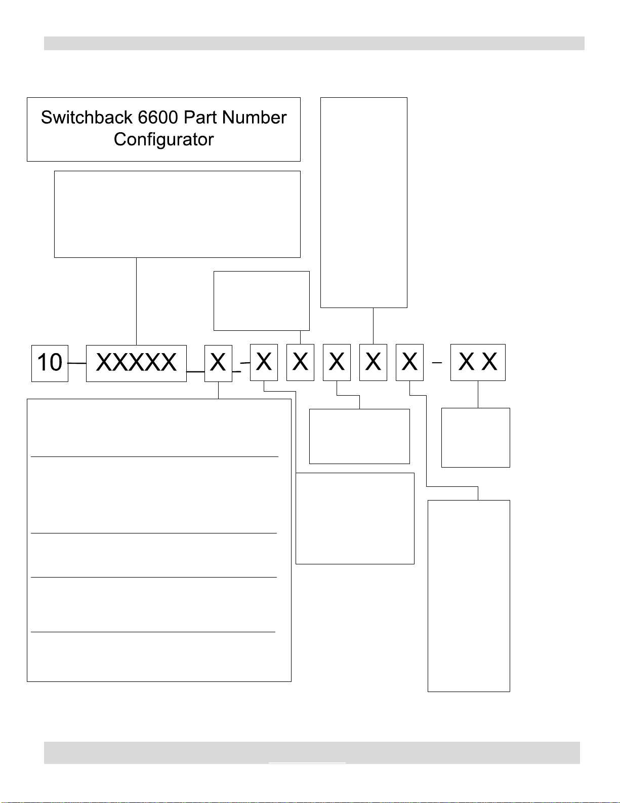
SWITCHBACK 6600 CE POWER SUPPLY CONFIGURATOR
Current Limit
Setting
A - 6.5 Amps
B - 8.5 Amps
C - 10.5 Amps
D - 12.5 Amps
E - 14.3 Amps
F - 16.3 Amps
G - 18.3 Amps
H - 20 Amps
I - 22 Amps
J - 24 Amps
K - 26 Amps
L - 28 Amps
M - 30 Amps
Governer Board Option Code
(PN 18-11346-3 for all but
Yoder board)
E - Rev Logic 4-20 mA, 50%
F - Rev Logic 4-20mA, 100%
G - Rev Logic 0-5V, 50%
H - Rev Logic 0-5V, 100%
0 – No Board (use zero)
SSCS Part Identifier
11147 - SwitchBack 6600
11422 - Switchback 6600R
12308 – Switchback 6600R Agilent
11596 - Switchback 6600TC
13310 – Switchback 6600 Power Supply/Temp Controller
w/Yokogawa UT55A PN 26-26147-1
Phase Monitor Board
Option
(PN 18-11475-1)
5 - PM Board
0 - No Board (zero)
GFCI Option:
(PN 18-11500-1)
6 - 30mA
0 - No Board (zero)
Voltage Limit
Setting
A - 14 VDC
B - 28 VDC
C - 43 VDC
D - 57 VDC
E - 71 VDC
F - 86 VDC
G - 100 VDC
H - 114 VDC
I - 130 VDC
J - 144 VDC
K - 158 VDC
L - 172 VDC
M - 186 VDC
N - 200 VDC
O - 216 VDC
P - 230 VDC
Customer
Special
Identifier
-19 = fixed
dip switches
Interface Cable Options: (all shielded):
* note: for temp controller Switchback add 2 feet to cable length
for build. Cable lengths below are from outside enclosure
Standard Cables Blue (2x14+2x22) - Replacement units only
A- 16-11320-8 = Std 8 ft cable (blue)
B- 16-11320-16 = Std 16 ft cable (blue)
C- 16-11320-20 = Std 20 ft cable (blue)
D- 16-11320-27 = Std 27 ft cable (blue)
E- 16-11320-16x = Std 16.3 ft cable w/o connector (blue)
High Temp Separate GND Cable 3x14+2x26 labeled Cooling
J- 16-11612-8C = 8 ft cable
K- 16-11612-16C = 16.3 ft (5 meter) cable
L- 16-11612-27C = 27 ft cable
High Temp Separate GND Cable 3x14+2x26 labeled Heating
R- 16-11612-8H = 8 ft cable
S- 16-11612-16H =16.3 ft (5 meter) cable
T- 16-11612-27H =27 ft cable
Hummel Connector High or Low Temp Sep GND 3x12+2x26
U- 16-13253-27 Black Chrome
V- 16-13253-27N Nickel Plated Internal
0- No Cable (use number zero as designator)
Note:ForCSH3000
GovernerBoardOptionsE
orGcannotbeused.
SWITCHBACK 6600 CE BIPOLAR DC POWER SUPPLY MANUAL PART NUMBER:52-11147-X
SOLID STATE COOLING SYSTEMS,167 MYERS CORNERS ROAD,WAPPINGERS FALLS,NY 12590
TELEPHONE:(845) 296-1300 FAX: (845) 296-1303 E-MAIL:WWW.SSCOOLING.COM VERSION:M6
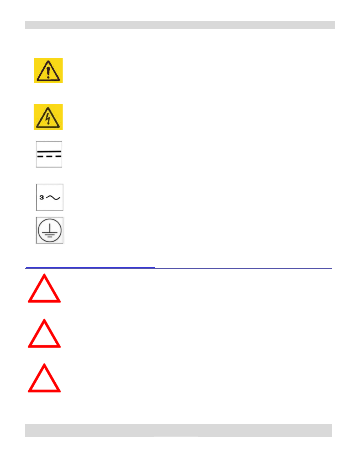
SYMBOLS USED ON POWER SUPPLY
To avoid electric shock, disconnect all power prior to servicing. The
power supply DC output is not isolated from the AC input. Input
power must be disconnected to prevent hazardous potentials
(approximately 145 volts) from appearing at the output, even when
voltage between output terminals is zero.
Caution. Risk of electric shock. Disconnect all power prior to
servicing.
Direct current.
Three-phase alternating current.
Protective conductor terminal.
SYMBOLS USED IN THIS MANUAL
The red CAUTION equilateral triangle symbol appears throughout the
manual. Please follow the important instructions accompanying this
symbol to avoid significant damage to the power supply.
The red WARNING equilateral triangle symbol appears throughout the
manual accompanying certain maintenance and repair activities. Please
follow the important instructions accompanying this symbol to avoid
situations that could cause injury to the operator or other personnel.
The red DANGER equilateral triangle symbol appears throughout the
manual accompanying certain maintenance and repair activities. Please
follow the important instructions accompanying this symbol to avoid
injury to the operator. Only trained personnel should undertake any
activity marked by the red DANGER triangle.
CAUTION
WARNING
DANGER

SWITCHBACK 6600 CE BIPOLAR DC POWER SUPPLY MANUAL PART NUMBER:52-11147-X
SOLID STATE COOLING SYSTEMS,167 MYERS CORNERS ROAD,WAPPINGERS FALLS,NY 12590
TELEPHONE:(845) 296-1300 FAX: (845) 296-1303 E-MAIL:WWW.SSCOOLING.COM VERSION:M6
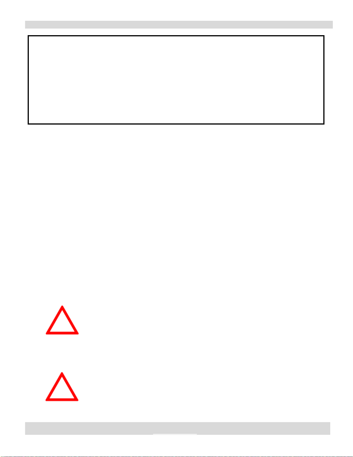
CAUTION
The output of the power supply MUST NOT be connected to secondary referenced circuitry. Input voltage
must be disconnected to prevent hazardous potentials from appearing at the output. DC control and logic
circuits are isolated from the AC line and DC output.
Do not operate the Switchback 6600 Power Supply at ambient air temperatures above 40°C (104 °F) or
below -10°C (14°F) as damage to the power supply could result.
With AC power disconnected, the power supply's enclosure may be removed temporarily to adjust the
current or voltage output limit dipswitch. Operation of the Switchback CE power supply with a non-original
enclosure or any replacement components will immediately void both Solid State Cooling Systems' warranty
and CE Mark.
If the power supply is turned on as per table 4, but the setpoint signal being used (pin 23 or 16) is
disconnected, the setpoint signal can float up to 5 V on its own causing maximum DC output. To avoid this:
1) Never disconnect the local or remote setpoint signal being used.
2) If using only remote setpoint, tie the local setpoint to signal ground.

SWITCHBACK 6600 CE BIPOLAR DC POWER SUPPLY MANUAL PART NUMBER:52-11147-X
SOLID STATE COOLING SYSTEMS,167 MYERS CORNERS ROAD,WAPPINGERS FALLS,NY 12590
TELEPHONE:(845) 296-1300 FAX: (845) 296-1303 E-MAIL:WWW.SSCOOLING.COM VERSION:M6
Switchback 6600 CE
Bipolar DC Power Supply
1.0 INTRODUCTION AND GENERAL DESCRIPTION
1.1 PURPOSE AND CAPABILITIES
The Switchback 6600 CE power supply is designed as a bipolar
current-controlled power supply for use with thermoelectric systems or
other predominately resistive loads. It provides a variable output
current in user-programmable ranges from 0-6.5 to 0-30 A at voltages
up to 230 VDC, with output current proportional to a 0-5 VDC input
signal. The maximum output voltage is also user-programmable from
14 to 230 VDC. The output is bipolar to allow both heating and cooling
in a thermoelectric system. This power supply also meets all CE Mark
(see declarations page at front of this manual) and Semi S2-0200 safety,
emissions, and immunity requirements. The Switchback 6600 CE
readily interfaces with a temperature controller (available separately) to
give a complete control system.
1.2 OPTIONAL FEATURES
The Switchback 6600CE power supply has four hardware options that
offer additional features over the standard model:
1.2.1 GOVERNOR BOARD
This feature “governs” the output current rate of change to a maximum
of 3% per second. When connected to a thermoelectric temperature
control system, this limit ensures maximum thermoelectric life by not
shocking the thermoelectric modules with sudden changes in DC
current or polarity. The governor board has a removable jumper to
allow use with the standard 0-5 VDC/digital polarity set-point signals
or with the dual 4-20 mA set-point signals.
The governor board has an additional jumper that allows the user to
limit the (-) polarity to 50% of maximum current. This feature can be
employed to match a thermoelectric systems heating and cooling
output, where, in the standard configuration, cooling is normal (+)
polarity and heating is (-) polarity.
PRODUCT
Manual

SWITCHBACK 6600 CE BIPOLAR DC POWER SUPPLY MANUAL PART NUMBER:52-11147-X
SOLID STATE COOLING SYSTEMS,167 MYERS CORNERS ROAD,WAPPINGERS FALLS,NY 12590
TELEPHONE:(845) 296-1300 FAX: (845) 296-1303 E-MAIL:WWW.SSCOOLING.COM VERSION:M6
This feature may be purchased with the standard Switchback 6600 CE
or in conjunction with the Phase Monitor.
1.2.2 PHASE MONITOR
Operation of the Switchback 6600CE power supply on only two phases
causes the output to approximate a 100-120 Hz rounded edge square
wave. The optional phase monitor will shut off the Switchback
6600CE if one or more input phase falls below 180 VAC. The phase
monitor board has a normally closed 0.5 amp 250 VAC dry contact
available on the output signal connector for external use. When the
voltage on the low phase increases to over 180 VAC the phase monitor
will automatically restart the power supply.
Note: Since phase alignment is not important to the Switchback 6600
CE Power Supply, the phase monitor does not check phase alignment.
This feature may be purchased with the standard Switchback 6600 CE
or in conjunction with the Governor Board.
1.2.4 GROUND FAULT INTERRUPT
This feature adds a ground fault interrupt circuit that shuts off the
power supply in the event of a ground fault. Power to the supply must
be cycled to restart after a ground fault.
The ground fault interrupt circuit trips at 30mA AC.
The GFCI option also adds an additional over voltage shutdown circuit
should the output voltage of the Switchback 6600 CE exceed 250 VDC.
This feature may be purchased with the standard Switchback 6600 CE
or in conjunction with the Governor Board, and/or Phase Monitor.
SWITCHBACK 6600 CE BIPOLAR DC POWER SUPPLY MANUAL PART NUMBER:52-11147-X
SOLID STATE COOLING SYSTEMS,167 MYERS CORNERS ROAD,WAPPINGERS FALLS,NY 12590
TELEPHONE:(845) 296-1300 FAX: (845) 296-1303 E-MAIL:WWW.SSCOOLING.COM VERSION:M6
2.0 INSTALLATION
2.1 INSPECTION
Inspect the shipping carton for possible damage before unpacking the
unit. Carefully unpack the equipment. Save all packing materials until
inspection is complete. Verify that all items listed on the packing slips
have been received. Visually inspect all exterior surfaces for broken
connectors, terminal blocks, dents or other damage. External damage
may be an indication of internal damage. If any damage is evident,
immediately contact the carrier who delivered the unit and submit a
damage report. Failure to do so could invalidate future claims.
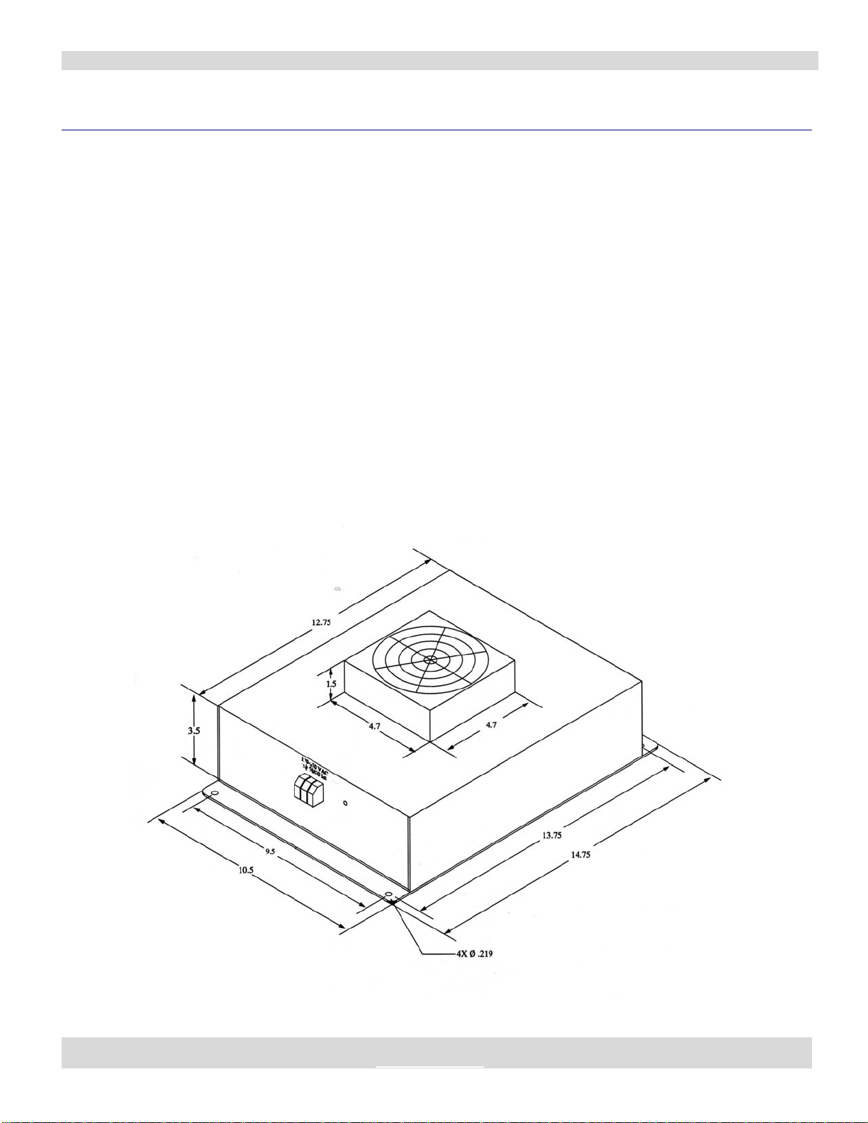
2.2 MOUNTING
The Switchback 6600 has two mounting flanges, one at each end (see
Figures 1 and 2) for mounting with 10-32 or M5 screws. The power
supply may be oriented in any direction.
***Important: Do not block the air intake or output areas.
One inch (2.5 cm.) clearance is required around these areas. ***
Figure 1: Switchback 6600 Enclosure, Front Perspective

SWITCHBACK 6600 CE BIPOLAR DC POWER SUPPLY MANUAL PART NUMBER:52-11147-X
SOLID STATE COOLING SYSTEMS,167 MYERS CORNERS ROAD,WAPPINGERS FALLS,NY 12590
TELEPHONE:(845) 296-1300 FAX: (845) 296-1303 E-MAIL:WWW.SSCOOLING.COM VERSION:M6
Figure 2: Switchback 6600 Enclosure, Rear Perspective
3.0 HOOKUP
3.1 POWER HOOKUP
Figure 3 shows the 200-240 VAC, 3-phase connections for Input
Power. Figure 4 shows the DC output connections.
Figure 3: Input Power Connections Figure 4: Output Power Connections
SWITCHBACK 6600 CE BIPOLAR DC POWER SUPPLY MANUAL PART NUMBER:52-11147-X
SOLID STATE COOLING SYSTEMS,167 MYERS CORNERS ROAD,WAPPINGERS FALLS,NY 12590
TELEPHONE:(845) 296-1300 FAX: (845) 296-1303 E-MAIL:WWW.SSCOOLING.COM VERSION:M6
3.2 MINIMUM SIGNAL HOOKUP REQUIRED
(See figures 5A & 5B)
In addition to the power connections, operation of the Switchback 6600
CE from one source of control signals requires three signals: Local
On/Off (pin 19), Local Set point (pin 23) and Local Polarity Control
(pin 22); or if using one of the 4-20 mA versions, Local On/Off (pin 19)
normal (Cool) Set point (pins 1 & 2) and reverse (Heat) Set point (pins
16 &17).
3.3 HOOKUP FOR TWO SOURCES OF CONTROL SIGNALS
(Not available on 4-20 mA versions)
The Switchback 6600 CE is designed to operate from two sources of
input, for example, the equipment front user interface or rear
maintenance panel. Local operation overrides remote operation. Local
operation may occur with remote operation off, but remote operation
may not occur unless local operation is on also. See Table 4 (Section
5.0) for details. Minimum hookup for two sources of input requires four
signals in addition to the three signal described in Section 3.2:
Remote/Local (pin 20), Remote On/Off (pin 18), Remote Set point (pin
16) and Remote Polarity (pin 17).
WARNING!
If the power supply is turned on as per Table 4 (Section 5), but the set
point signal being used (pin 23 or 16) is disconnected, the set point
signal can float up to 5 V on its own, causing maximum DC output.
To avoid this:
1) Never disconnect the local or remote set point signal being used.
2) If using only remote set point, tie the local set point to signal
ground.
3.4 INPUT PROTECTION
A suitable 3-phase, 250 V, 30 amp, AC protector, such as circuit UL
489 rated circuit breaker, SHOULD be provided by the user to protect
against failures in the regulator.
Notice to Users Required to Meet CE Emissions:
Two clamp-on ferrite beads are included with your Switchback 6600 Bipolar DC Power Supply. To
meet CE conducted emissions, you must thread your two DC output wires through the cylindrical
ferrite bead and clamp the square ferrite bead around your 3-phase AC input wires. The ferrite beads
should be placed within one foot of the power supply case.
Radiated emissions from an installed Switchback 6600 Bipolar DC Power Supply are affected by the
length of the DC output wires. To ensure the installed unit meets CE radiated emissions specifications,
the DC output wires should be placed inside a flexible metallic sheath, such as BX cable.
WARNING
WARNING
SWITCHBACK 6600 CE BIPOLAR DC POWER SUPPLY MANUAL PART NUMBER:52-11147-X
SOLID STATE COOLING SYSTEMS,167 MYERS CORNERS ROAD,WAPPINGERS FALLS,NY 12590
TELEPHONE:(845) 296-1300 FAX: (845) 296-1303 E-MAIL:WWW.SSCOOLING.COM VERSION:M6
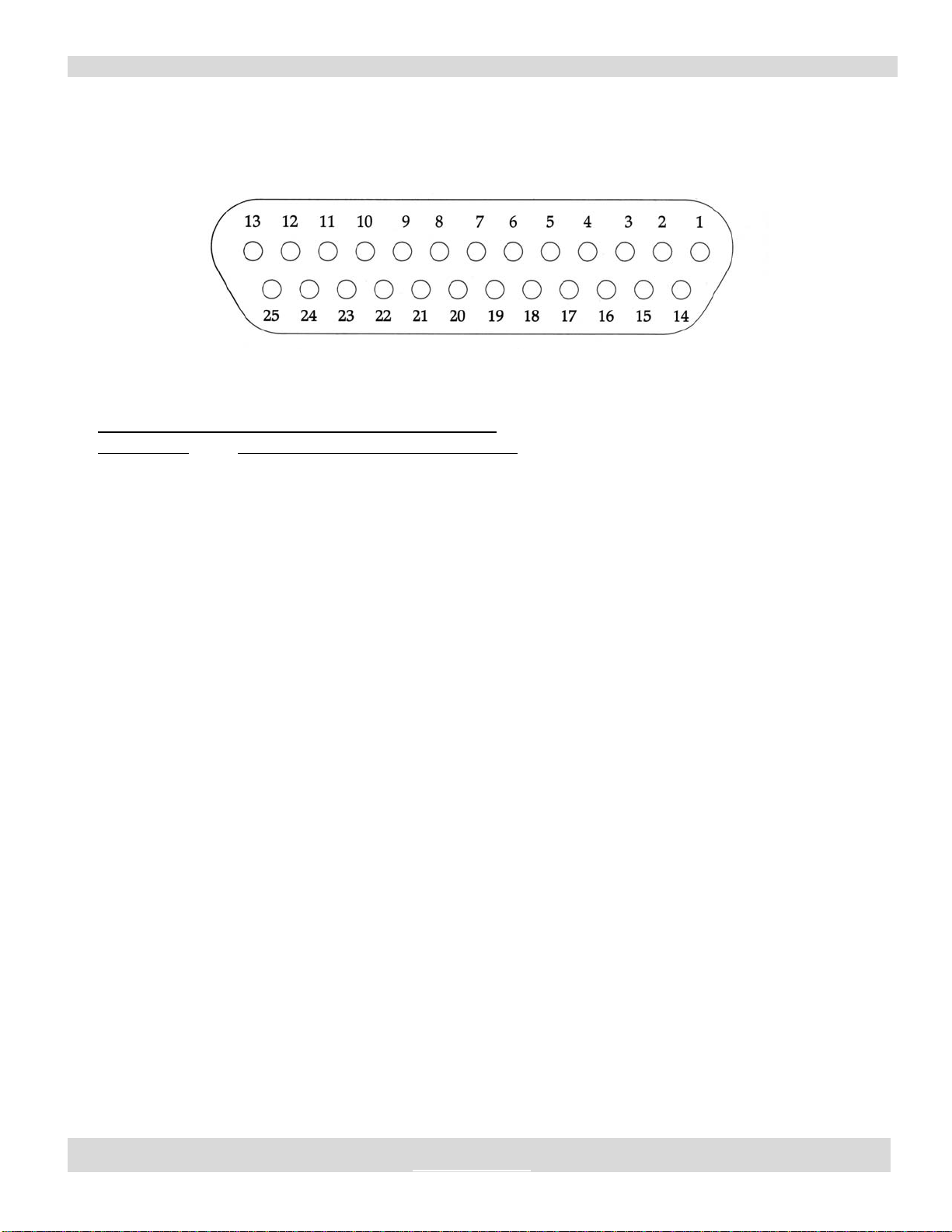
Figure 5A
Standard Signal Connector
25 pin D-subminiature Receptacle
Table 1A: DB-25 Signal Connector Pin Descriptions
Pin Number Description
1Optional NC Phase loss Dry Contact (0.5 A)
2Optional NC Phase loss Dry Contact (0.5 A)
3Signal Ground
4Signal Ground
5Signal Ground
6Signal Ground
7Signal Ground
8Signal Ground
9Signal Ground
10 + 5 VDC
11 Spare
12 Spare
13 Spare
14 Bi-Directional Fault Signal
15 + 12 VDC
16 Remote Set point
17 Remote Polarity Control
18 Remote On/Off
19 Local On/Off
20 Remote/Local Operation
21 Proportional Output Current
22 Local Polarity Control (TTL)
23 Local Set point (0-5 VDC)
24 Spare
25 Spare
SWITCHBACK 6600 CE BIPOLAR DC POWER SUPPLY MANUAL PART NUMBER:52-11147-X
SOLID STATE COOLING SYSTEMS,167 MYERS CORNERS ROAD,WAPPINGERS FALLS,NY 12590
TELEPHONE:(845) 296-1300 FAX: (845) 296-1303 E-MAIL:WWW.SSCOOLING.COM VERSION:M6
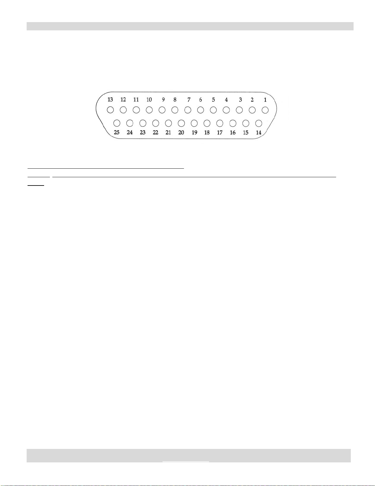
Figure 5B
Signal Connector – Governor Board
25 pin D-subminiature Receptacle
Table 1C: DB-25 Signal Connector Pin Descriptions
Pin No. Description (4-20 mA Set point) Description (0-5 VDC Set point)
1Cool 4-20 mA (+) Spare
2Cool 4-20 mA (-) Spare
3 Signal Ground Signal Ground
4 Signal Ground Signal Ground
5 Signal Ground Signal Ground
6 Signal Ground Signal Ground
7 Signal Ground Signal Ground
8 Signal Ground Signal Ground
9 Signal Ground Signal Ground
10 + 5 VDC + 5 VDC
11 Spare Spare
12 Spare Spare
13 Spare Spare
14 Bi-Directional Fault Signal Bi-Directional Fault Signal
15 + 12 VDC + 12 VDC
16 Heat 4-20 mA (+) Spare
17 Heat 4-20 mA (-) Spare
18 Spare Spare
19 Local On/Off Local On/Off
20 Spare Spare
21. Proportional Output Current Proportional Output Current
22 Spare Polarity Control (TTL)
23 Spare Set point (0-5 VDC)
24 Optional NC Phase Loss Dry Contact (0.5 Amp) Optional NC Phase Loss Dry Contact (0.5 Amp)
25 Optional NC Phase Loss Dry Contact (0.5 Amp) Optional NC Phase Loss Dry Contact (0.5 Amp)
SWITCHBACK 6600 CE BIPOLAR DC POWER SUPPLY MANUAL PART NUMBER:52-11147-X
SOLID STATE COOLING SYSTEMS,167 MYERS CORNERS ROAD,WAPPINGERS FALLS,NY 12590
TELEPHONE:(845) 296-1300 FAX: (845) 296-1303 E-MAIL:WWW.SSCOOLING.COM VERSION:M6
4.0 SPECIFICATIONS
4.1 NON-ISOLATED OUTPUT
The output of the power supply is not isolated from the AC input. The
output of the power supply MUST NOT be connected to secondary
referenced circuitry. Input voltage must be disconnected to prevent
hazardous potentials from appearing at the output. DC control and
logic circuits are isolated from the AC line and DC output.
4.2 INPUT POWER REQUIREMENTS
The Switchback 6600 power supply requires 200-240 (+5%) VAC, 3-
phase, WYE, 50 or 60 Hz, and 22 A. Input 3-phase power must be in a
WYE configuration.
4.3 INPUT SOURCE IMPEDANCE
Source impedance on 200-240 (+5%) VAC input must be less than or
equal to 200 μH
4.4 INPUT PROTECTION
A suitable 3-phase, 250 V, 30 amp, AC protector, such as circuit UL
489 rated circuit breaker, SHOULD be provided by the user to protect
against failures in the regulator.
4.5 LINE FILTERING
The power supply has an integral line filter, which meets EN55011
Class A conducted emissions requirements.
4.6 SIZE AND WEIGHT
The Switchback 6600 power supply weighs 19 lbs. with dimensions of
12.75” (plus two 1” mounting flanges) x 5” x 10.5”.
WARNING
WARNING
SWITCHBACK 6600 CE BIPOLAR DC POWER SUPPLY MANUAL PART NUMBER:52-11147-X
SOLID STATE COOLING SYSTEMS,167 MYERS CORNERS ROAD,WAPPINGERS FALLS,NY 12590
TELEPHONE:(845) 296-1300 FAX: (845) 296-1303 E-MAIL:WWW.SSCOOLING.COM VERSION:M6
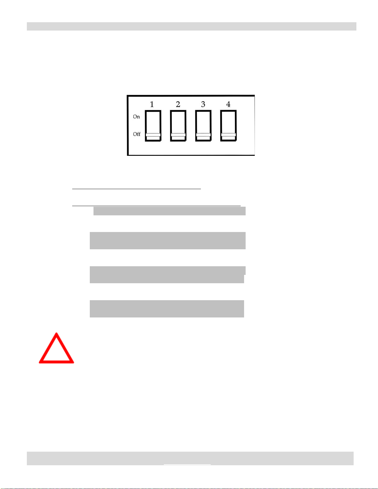
4.7 MAXIMUM OUTPUT CURRENT
The output current is dipswitch adjustable by the user in ranges from
0-6.5 to 0-30A in increments of 2A. The dipswitch, located on the
motherboard towards the rear under the horizontal daughter board, sets
the output current range as follows:
Figure 6: Sketch of 4-Position Current Dip-Switch
Table 2. Current Limit Dip-Switch Settings
Maximum Output Dip-Switch Position
Current (Amps) 1 2 3 4
6.5 OFF OFF OFF OFF
8.5 ON OFF OFF OFF
10.5 OFF ON OFF OFF
12.5 ON ON OFF OFF
14.3 OFF OFF ON OFF
16.3 ON OFF ON OFF
18.3 OFF ON ON OFF
20.0 ON ON ON OFF
22.0 ON ON OFF ON
24.0 OFF OFF ON ON
26.0 ON OFF ON ON
28.0 OFF ON ON ON
30.0 ON ON ON ON
Danger: Hazardous Voltages Present!
Input power to the Switchback 6600 CE power supply must be
disconnected when changing a jumper or dip-switch position.
DANGER

SWITCHBACK 6600 CE BIPOLAR DC POWER SUPPLY MANUAL PART NUMBER:52-11147-X
SOLID STATE COOLING SYSTEMS,167 MYERS CORNERS ROAD,WAPPINGERS FALLS,NY 12590
TELEPHONE:(845) 296-1300 FAX: (845) 296-1303 E-MAIL:WWW.SSCOOLING.COM VERSION:M6
4.8 MAXIMUM OUTPUT VOLTAGE
The maximum output is adjustable by the user via a dipswitch from 14-
230 V in increments of approximately 14 V. The dipswitch, located on
the horizontal daughter board towards the rear and near the heat sink,
sets the maximum output current as follows:
Figure 7: Sketch of 4-Position Current Dip-Switch
Table 3. Voltage Limit Dip-Switch Settings
Maximum Output Dip-Switch Position
Voltage (Volts) 1 2 3 4
14 OFF OFF OFF OFF
28 OFF OFF OFF ON
43 OFF OFF ON OFF
57 OFF ON ON OFF
71 OFF ON OFF OFF
86 OFF ON OFF ON
100 OFF ON ON OFF
114 OFF ON ON ON
130 ON OFF OFF OFF
144 ON OFF OFF ON
158 ON OFF ON OFF
172 ON OFF ON ON
186 ON ON OFF OFF
200 ON ON OFF ON
216 ON ON ON OFF
230 ON ON ON ON
Danger: Hazardous Voltages Present!
Input power to the Switchback 6600 CE power supply must be
disconnected when changing a jumper or dip-switch position.
DANGER

SWITCHBACK 6600 CE BIPOLAR DC POWER SUPPLY MANUAL PART NUMBER:52-11147-X
SOLID STATE COOLING SYSTEMS,167 MYERS CORNERS ROAD,WAPPINGERS FALLS,NY 12590
TELEPHONE:(845) 296-1300 FAX: (845) 296-1303 E-MAIL:WWW.SSCOOLING.COM VERSION:M6
4.9 RECOMMENDED LOAD RESISTANCE
The output of the power supply will operate with I/V characteristics
0-30 A and 0-230 VDC into a resistive load over the full range of input
power. To take full advantage of the current ranges available, the load
resistance (R) should be:
400 m< R < 37
Inductive loads are not recommended. The Switchback 6600 cannot
operate as a current sink for a servomotor or other inductive load.
4.10 TRANSIENT RESPONSE
The output current will regulate within 10 milliseconds of a set point
change or load transient of up to 50%. The product of the combined
load + distribution resistance and inductance shall be less than 50
microseconds.
4.11 CONTROL BANDWIDTH
The current control loop bandwidth varies with the load resistance
(RLOAD) by the following relationship:
Bandwidth = 5288/RLOAD (Hz)
4.12 REGULATION (OUTPUT ACCURACY)
The actual output will not vary from the output current set point by
more than 5% of actual output current or ± 0.5 Amps, whichever is
greater.
4.13 OUTPUT RIPPLE AND NOISE
Peak to peak output ripple voltage shall not exceed 5% of the DC
output voltage for output voltages greater than 50 Volts when attached
to a resistive load and measured to a bandwidth up to 100 kHz. Below
50 volts of output voltage, the ripple voltage shall not exceed 2.5 volts
peak to peak measured to a bandwidth up to 100 kHz.
4.14 SIGNAL ISOLATION
With the 3 phase power input and 2 power output terminals tied
together, the power supply will withstand a 3000 VDC Hipot from
these power leads to all signals in the signal interface and the earth
ground post. The signal interface is considered earthed secondary
circuitry by connecting this post.

SWITCHBACK 6600 CE BIPOLAR DC POWER SUPPLY MANUAL PART NUMBER:52-11147-X
SOLID STATE COOLING SYSTEMS,167 MYERS CORNERS ROAD,WAPPINGERS FALLS,NY 12590
TELEPHONE:(845) 296-1300 FAX: (845) 296-1303 E-MAIL:WWW.SSCOOLING.COM VERSION:M6
4.15 THERMAL PROTECTION
The aluminum heat sink has a thermal protection switch attached that
will shut off the power supply output should the heat sink temperature
reach 70 °C. The switch will automatically reset at 53 °C, restarting the
power supply. The power supply fault signal, DB-25 pin 14, will switch
to TTL low when thermal shut-off occurs.
4.15 OUTPUT POWER OVERLOAD/SHORTS TO GROUND
The power supply is protected against output shorts between terminals
and direct shorts to ground.
Should an output short occur, the output stage will overload and shut
down. The power supply fault signal, DB-14, will switch to TTL low
when the output stage overloads. If this occurs, input power to the
Switchback 6600 CE must be turned off and then back on to reset the
power supply.
The power supply may also shut down if the output polarity is switched
at high current levels (see Section 5.5). The power supply will not be
damaged, but the input power must be turned off and then back on to
reset the power supply.
4.16 OPERATING TEMPERATURES
The power supply may operate in ambient temperatures from 0-40 °C.
Maximum operating humidity is 80%, non-condensing.
4.17 PHASE MONITOR OPTION
The optional phase monitor shuts off the Switchback 6600 CE and
triggers the bi-directional fault signal if one or more input phase falls
below 180 VAC. When the voltage on the low phase increases to over
180 VAC the phase monitor will automatically restart the power
supply. The phase monitor does not check phase alignment.
The phase monitor option includes 0.5 amps 250 V rated normally
closed (NC) dry contact for external use (see figures 5A & 5B) for pin
location).
4.18 GROUND FAULT INTERRUPT OPTION
The GFCI option shuts off the Switchback 6600 CE and triggers the bi-
directional fault signal when the ground current reaches a preset limit of
30 mA.

SWITCHBACK 6600 CE BIPOLAR DC POWER SUPPLY MANUAL PART NUMBER:52-11147-X
SOLID STATE COOLING SYSTEMS,167 MYERS CORNERS ROAD,WAPPINGERS FALLS,NY 12590
TELEPHONE:(845) 296-1300 FAX: (845) 296-1303 E-MAIL:WWW.SSCOOLING.COM VERSION:M6
5.0 OPERATING INSTRUCTIONS
The Switchback 6600 Power Supply is operated via control signals
through the DB-25 connector. The power supply has two operating
modes: remote and local. Table 4 lists the internal logic for remote or
local operation via the three TTL signals, which control the operating
mode (Local/Remote, Remote On/Off, Local On/Off).
Table 4: Logic for Remote and Local Operation
(Note: Remote operation not available with Governor board option)
Remote Local Local Output Status
ON/OFF (Pin 18) ON/Off (Pin 19) Remote (Pin 20) and Control
Low Low Low On/Remote
Low Low High On/Local
Low High Low Off
Low High High Off
High Low Low Off
High Low High On/Local
High High Low Off
High High High Off
The recommended method for pulling down one of the above signals
from high to low are via a contact closure between the signal pin above
and one of the signal grounds (pins 3–9). A transistor, relay, or switch
may be used to effect the contact closure.
5.1 LOCAL/REMOTE SELECTOR SIGNAL INPUT
DB-25 pin# 20 selects the output current of the power supply to be set
by the LOCAL input or the REMOTE input. A TTL high or open
circuit on this pin causes the power supply to regulate to the LOCAL
input. A TTL low on this pin causes the power supply to regulate to the
REMOTE input.
5.2 REMOTE ON/OFF
DB-25 pin# 18 will cause the output to be OFF when a TTL high (or
open circuit) is applied or on when a TTL low is applied. In the OFF
state, leakage current from the power supply will be no greater than 50
milliamps.
This manual suits for next models
3
Table of contents


