SolPad SolarIQ 500HD-W-6-4G User manual

1
101 Metro Plaza • Suite 315 • San Jose, CA 95110 • (800) 801-4186 © 2020 SolPad Inc.
SolPad Load Controller
Installation
Version 1.8 ● 06 February 2020
101 Metro Plaza, Suite 315, CA 95110
www.solpad.com
2
101 Metro Plaza • Suite 315 • San Jose, CA 95110 • (800) 801-4186 © 2020 SolPad Inc.
Perform all electrical installations in accordance with all applicable local electrical
codes, such as: NPFA 70 (NEC); and ANSI requirements.
WARNING: Incorrect installation and/or operation can cause serious injury or death
to personnel and damage to equipment and/or property. Only qualified personnel are
authorized to install and/or maintain a SolPad device.
WARNING: Use insulated tools to reduce the risk of electrical shock or accidental
short circuits. Remove all jewelry, such as rings, watches, bracelets, etc., when
installing or performing maintenance on the SolPad platform.
WARNING: An electric shock or fire can be fatal to personnel. Inadequately sized
wiring and/or overcurrent protection can cause serious injury or death to personnel
and damage to equipment and/or property.
WARNING: Inadequate grounding methods/conductors can cause serious injury or
death to personnel and damage to equipment and/or property. The grounding
system/conductors must be installed per NEC or CEC requirements.
WARNING: Before servicing a SolPad Load Controller system or replacing any part
of a system you must de-energize the system by flipping the units dedicated circuit
breaker to the off position.
CAUTION: Do not mount or install a SolPad component where is it subject to
physical damage from the surrounding area.
Info: SolPad may choose to revoke any and all warranty of a SolPad system if
visible physical damage due to mishandling, improper installation, or electrical arcing
is present on any component associated with the installation process.

3
101 Metro Plaza • Suite 315 • San Jose, CA 95110 • (800) 801-4186 © 2020 SolPad Inc.
Table of Contents
1. Special Section: Connecting Loads .......................................................................................... 6
1.1 About this section ............................................................................................................ 6
1.2 Connection Examples ....................................................................................................... 6
20A / 120V Circuit Connection ................................................................................................ 6
................................................................................................................................................. 6
Water Heater Connection (30A / 240V) ................................................................................. 6
Clothes Dryer Connection (30A / 240V) ................................................................................. 7
Pool or Spa HEATER (30A / 240V) ........................................................................................... 7
Pool or Spa PUMP (30A / 240V) .............................................................................................. 8
HVAC – Air Handler (30A / 240V) ............................................................................................ 8
HVAC – Control via low voltage; A/C Compressor and Fan are controlled ............................ 9
HVAC Connection – A/C and Heat Control via low voltage – Fan is not controlled ............... 9
Electric Kitchen Range controlled with 50-amp breaker ...................................................... 10
2. The SolPad Load Controller ................................................................................................... 11
2.1 Introduction.................................................................................................................... 11
2.2 SolPad Load Controller Product Line .............................................................................. 11
6 Relay Load Controller: SolarIQ 500HD-W-6-4G ................................................................. 11
12 Relay Load Controller: SolarIQ 500HD-W-12-4G ............................................................. 11
24 Relay Load Controller: SolarIQ 500HD-W-24-4G ............................................................. 11
32 Relay Load Controller: SolarIQ 500HD-W-32-4G ............................................................. 11
2.3 Tools and Materials ........................................................................................................ 12
Recommended Materials ...................................................................................................... 12
Recommended Tools ............................................................................................................ 12
2.4 Unpacking – What you will find in the box .................................................................... 12
................................................................................................................................................... 13
Loose Parts ............................................................................................................................ 13
2.5 System Components and Descriptions .......................................................................... 14
SolPad CPU – CompuLab ....................................................................................................... 14

4
101 Metro Plaza • Suite 315 • San Jose, CA 95110 • (800) 801-4186 © 2020 SolPad Inc.
Power Supply ........................................................................................................................ 15
MOTES – Marvel of Tiny Engineering ................................................................................... 15
4G High Gain Antenna / RS485 Adapter / Wi-Fi Antenna .................................................... 16
2.6 Relay Descriptions .......................................................................................................... 17
................................................................................................................................................... 17
20 Amp SPDT 240vac Relays ................................................................................................. 17
30 Amp DPDT 240vac Ice Cube Relays .................................................................................. 17
50 Amp DPDT 240vac Open Frame Relays ........................................................................... 18
3. Installation ............................................................................................................................ 19
Installation Steps ................................................................................................................... 19
3.1 Mounting the Enclosure ................................................................................................. 19
3.2 Source Power for the System ......................................................................................... 20
3.3 Connectivity and Accessories ......................................................................................... 20
4G, Wi-Fi, RS485 .................................................................................................................... 21
3.4 Installation of Current Transducers (CTs) ...................................................................... 22
Mains / Grid Power ............................................................................................................... 23
Battery Max Customers with AC Coupled Batteries ............................................................. 24
Battery Max Customers with DC Coupled Batteries ............................................................. 25
Demand Customers with Solar ............................................................................................. 25
................................................................................................................................................... 26
3.5 Connecting Loads ........................................................................................................... 26
............................................................................................................................................... 26
Populate the Cover Label ...................................................................................................... 26
3.6 Power up the Load Controller ........................................................................................ 27
3.7 Installer Checklist ........................................................................................................... 28
3.8 System Verification, Test & Turn-up .............................................................................. 28
4. FAQ’s ..................................................................................................................................... 30
What is Demand? .................................................................................................................. 30
How do utilities charge for demand? ................................................................................... 30
Can you explain On Peak and Off Peak? ............................................................................... 30
What does a SolPad demand management system do? ...................................................... 30

5
101 Metro Plaza • Suite 315 • San Jose, CA 95110 • (800) 801-4186 © 2020 SolPad Inc.
My clothes dryer turns on and tumbles but does not heat up, is my dryer broken? .......... 30
What systems and appliances does the SolPad system typically control? ........................... 31

6
101 Metro Plaza • Suite 315 • San Jose, CA 95110 • (800) 801-4186 © 2020 SolPad Inc.
1. Special Section: Connecting Loads
1.1 About this section
This ‘Connecting’ section is located at the front of the guide to serve as an easy-to-find
reference offering examples for certain use cases. Before beginning a SolPad Load
Controller installation you must read the entire guide and carefully follow each step.
THESE CONNECTIONS EXAMPLES ARE NOT TO BE CONSIDERED AS DETAILED WIRING
DIAGRAMS. ANY INSTALLATION WITH A SOLPAD LOAD CONTROLLER MUST BE COMPLETED
IN ACCORDANCE WITH ALL APPLICABLE LOCAL ELECTRICAL CODES BY A
LICENSED ELECTRICIAN.
1.2 Connection Examples
20A / 120V Circuit Connection
To control a typical 120v circuit in a residence, you’ll
interrupt the line conductor at the breaker and land
it on the relay in the load controller.
In the electric panel, interrupt the load’s L1
conductor and run it to the normally closed
(N.C.) contact on the 20-amp relay.
Run a second conductor from the relay’s
COM terminal back to the circuit breaker.
See 20-amp SPDT Relay information in section 2.6
Water Heater Connection (30A / 240V)
Water heaters are often low priority items for
control and among the first to shed. For each
water heater, disconnect one leg from the circuit
breaker.
In the electric panel, interrupt either the
L1 or L2 conductor and run it to the
normally closed (N.C.) contact on the 30A
relay.
Run another conductor from the relay’s
COM terminal back to the circuit breaker.
See 30 Amp DPDT Relay information in section 2.

7
101 Metro Plaza • Suite 315 • San Jose, CA 95110 • (800) 801-4186 © 2020 SolPad Inc.
Clothes Dryer Connection (30A / 240V)
Disconnect the leg which supplies the heating
element ONLY, so the motor and controls are still
allowed to run. Determine the correct leg through
trial and error. Disconnect one leg from the circuit
breaker, and then test the dryer. If you the motor
and controls work but there is no heat, the correct
leg has been disconnected.
Some heaters have 220V motors which are trickier,
but if eliminate the heat, you have disconnected
the correct leg.
In the electric panel, interrupt L1 or L2
(whichever is the heating element leg) and
run it to the normally closed (N.C.) contact
on the 30A relay.
Run another conductor from the relay’s COM terminal back to the circuit breaker.
See 30 Amp DPDT Relay information in section 2.6
Pool or Spa HEATER (30A / 240V)
As with Clothes Dryers, you want to disconnect the
leg suppling the heating element ONLY. Determine
which leg is which is through trial and error.
Disconnect one leg from the circuit breaker, and
then test the heater. If you the motor and controls
work but there is no heat, the correct leg has been
disconnected.
In the electric panel, interrupt L1 or L2
(whichever is the heating element leg) and
run it to the normally closed (N.C.) contact
on the 30A relay.
Run another conductor from the relay’s
COM terminal back to the circuit breaker.
NOTE: Advise the customer once wiring is complete that reprogramming of their Pool or
Spa timer may be required, and to take into account the “On-Peak” periods when doing so.
See 30 Amp DPDT Relay information in section 2.6
8
101 Metro Plaza • Suite 315 • San Jose, CA 95110 • (800) 801-4186 © 2020 SolPad Inc.
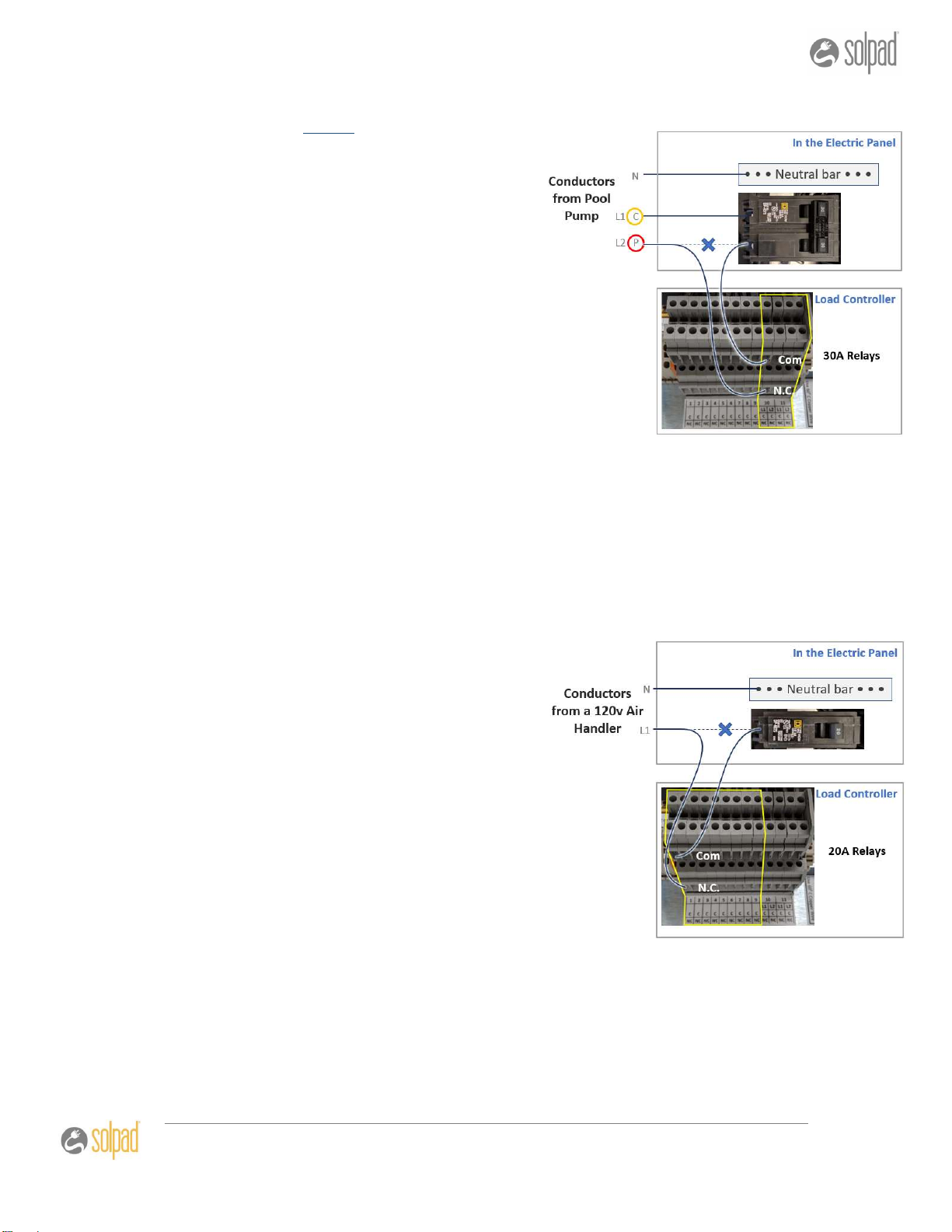
Pool or Spa PUMP (30A / 240V)
As with Clothes Dryers, you want to disconnect
the supply leg which breaks the pump ONLY.
Determine the proper leg to control by trial and
error. Disconnect one leg from the circuit
breaker, and then test the pump. If you the
controls work but there is no pumping, the
correct leg has been disconnected.
In the electric panel, interrupt L1 or L2
(whichever is the pumping element leg)
and run it to the normally closed (N.C.)
contact on the 30A relay.
Run another conductor from the relay’s
COM terminal back to the circuit
breaker.
NOTE: Advise the customer once wiring is complete that reprogramming of their Pool or
Spa timer may be required, and to take into account the “On-Peak” periods when doing so.
See 30 Amp DPDT Relay information in section 2.6
HVAC – Air Handler (20A / 120V)
Air Conditioners and Air Handlers are normally
high priority items for control, and typically the
last or next to last to shed. In this configuration
the Line between the unit and the breaker is
interrupted.
In the electric panel, interrupt the load’s
L1 conductor and run it to the normally
closed (N.C.) contact on the 20-amp
relay.
Run a second conductor from the relay’s
COM contact back to the terminal on
the circuit breaker.
See 20-amp SPDT Relay information in section 2.6
9
101 Metro Plaza • Suite 315 • San Jose, CA 95110 • (800) 801-4186 © 2020 SolPad Inc.
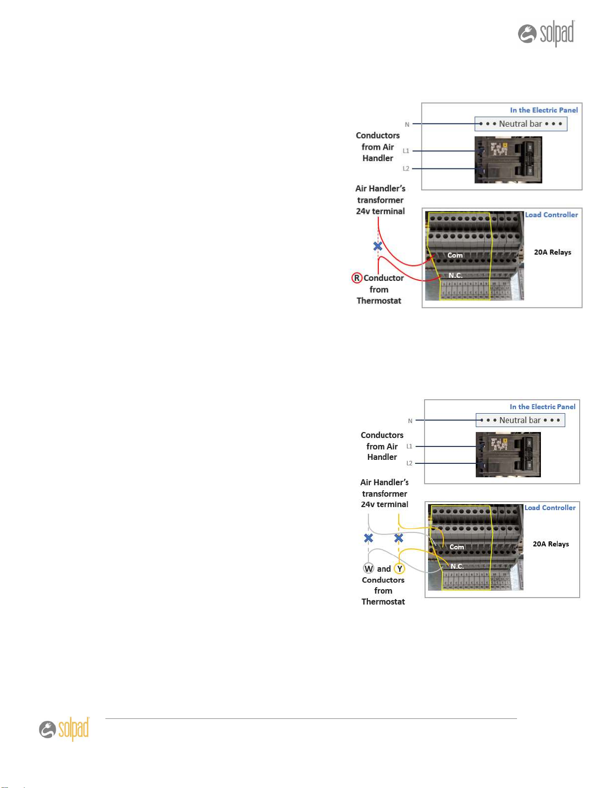
HVAC – Control via low voltage; A/C Compressor and Fan are
controlled
Air Conditioners can be controlled through their
low voltage thermostat wires. In this
configuration you’ll interrupt the red conductor
running from the thermostat to the unit’s
internal transformer.
The red (R) conductor from the
thermostat needs to be disconnected
from the air-handler transformer’s 24v
terminal. Run this conductor instead to
the normally closed (N.C.) contact on
the 20-amp relay.
Run another conductor from the relay’s
COM terminal to the 24v terminal on
the air-handler’s transformer.
See 20-amp SPDT Relay information in section 2.6
HVAC Connection – A/C and Heat Control via low voltage – Fan is not
controlled
For this configuration you’ll interrupt the white
(W) and yellow (Y) conductors that run from the
thermostat to the air handling unit.
For the W conductor to control heat:
Run the W conductor from the
thermostat to the normally closed (NC)
terminal on a 20-amp relay.
Run a second conductor from the relay’s
COM terminal to the heat terminal on the
air handler unit.
For the Y conductor to control cool:
Run the Y conductor from the thermostat
to the normally closed (NC) terminal on a second 20-amp relay.
Run a second conductor from the relay’s COM terminal to the heat terminal on the
air handler unit.
NOTE: this takes 2ea 20-amp relays. See 20-amp SPDT Relay information in section 2.6

10
101 Metro Plaza • Suite 315 • San Jose, CA 95110 • (800) 801-4186 © 2020 SolPad Inc.
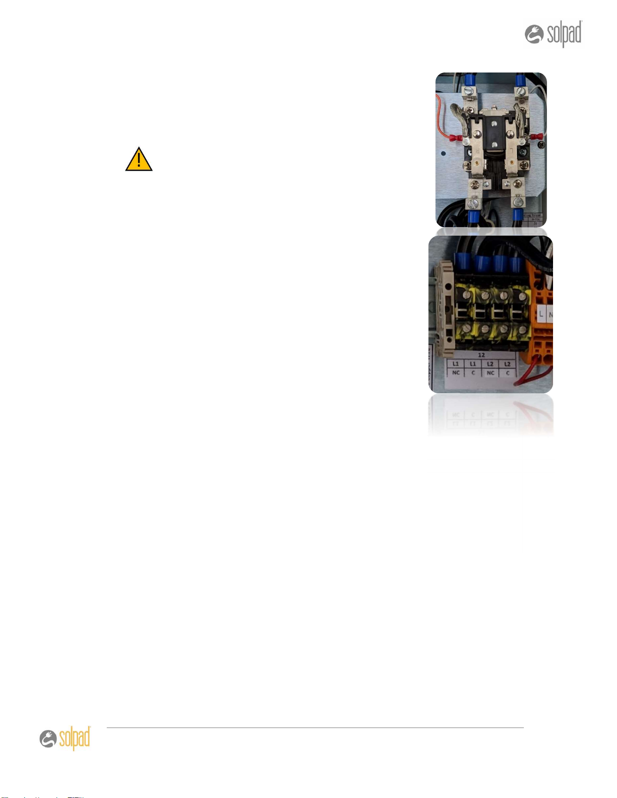
Electric Kitchen Range controlled with 50-amp breaker
For this configuration you’ll interrupt
both L1 and L2.
The 50-amp relay terminals are located
on the yellow terminal block.
Interrupt L1 and L2 coming from
the range, and land them on their
respective ‘NC’ terminals on the
50-amp relay block.
Then run new L1 and L2
conductors from their respective
‘C’ terminals back the two-pole
breaker in the panel.
See 50 Amp DPDT 240vac Open-frame Relay information in section 2.6

11
101 Metro Plaza • Suite 315 • San Jose, CA 95110 • (800) 801-4186 © 2020 SolPad Inc.
2. The SolPad Load Controller
2.1 Introduction
Congratulations on your purchase of the SolPad Load Controller
This system was designed using our 4 decades of experience to provide you with an
accurate, reliable and flexible system for you to control your electrical demand and power
use. This manual covers an overview of the product, safety information, installation
instructions, for a variety of models with slight variations.
**IMPORTANT NOTE: This Energy Management System is to be installed by a professional
electrician.
2.2 SolPad Load Controller Product Line
SolPad carries four different Load Controller options to cover a variety of customer needs.
6 Relay Load Controller: SolarIQ 500HD-W-6-4G
Control six circuits using:
(4) 20A relays
(2) 30A relays
12 Relay Load Controller: SolarIQ 500HD-W-12-4G
Control t12 circuits using:
(4) 20A relays
(2) 30A relays
(1) 50A relay
24 Relay Load Controller: SolarIQ 500HD-W-24-4G
Control 24 circuits using:
(19) 20A relays
(4) 30A relays
(1) 50A relay
32 Relay Load Controller: SolarIQ 500HD-W-32-4G
Control 32 circuits using:
(26) 20A relays
(4) 30A relays
(2) 50A relay

12
101 Metro Plaza • Suite 315 • San Jose, CA 95110 • (800) 801-4186 © 2020 SolPad Inc.
2.3 Tools and Materials
While this is not intended to be an exhaustive list of materials and tools required, it is
intended to provide you with the items that are often necessary (and not on hand) to
complete a typical installation and not included with the system as purchased.
Recommended Materials
1. CTs for the Main Service.
2. CTs for PV production monitoring.
3. 15amp dedicated breaker for EMS power source.
4. 18/2 or 18/4 Stranded, Unshielded control cable (for CTs).
5. 18/4 Stranded, Shielded Wire (for use with Rogowski Coil or other 4-20ma
applications).
6. CT Kit – Provides installer with CT options should the supplied CTs not fit.
7. Mounting hardware for the enclosure based on site requirements.
8. 14ga and 10ga stranded conductor.
9. Wire nuts or multitaps for above.
10. 1” minimum EMT, and necessary connectors based on site requirements
Recommended Tools
1. Voltage meter and Amp Meter for CT Calibration.
2. Laptop Computer with TeamViewer v11 preloaded.
3. CAT5 patch cable to connect Laptop to CPU.
4. Small instrument screw drivers for terminating CT conductors on the MOTES.
5. Stepper or Unibit for mounting the 4G high gain antenna.
2.4 Unpacking – What you will find in the box
Before opening the box, inspect the box itself for signs of damage as that will require further
inspection of the contents to ensure components are damage free.

13
101 Metro Plaza • Suite 315 • San Jose, CA 95110 • (800) 801-4186 © 2020 SolPad Inc.
Even though the system is fully tested before shipment and the enclosure is carefully
packaged to protect the electrical components inside during shipment, wires and plugs may
come loose during shipping. Check all terminals and wires to ensure they are properly
seated. Push down on the terminals to make sure they’re secure, lightly tug on the wire
connections to make sure they won’t fall out during installation. Also, make sure the relays
are all firmly seated in the black relay bases located on the middle-right side of the panel.
The enclosure may come with a small white cardboard box or zip lock bag that contains
accessories necessary to complete the installation. The CPU may come already installed on
the din-rail on the top left of the panel as shown above, or inside the accessory box.
Loose Parts
For an IQ 500HD-W-6-4G, the following accessories
will be included
1ea - 4G high gain antenna
1ea - Adapter for the 4G antenna
1ea – 4-amp Circuit Breaker
1ea - Wi-Fi antenna
14
101 Metro Plaza • Suite 315 • San Jose, CA 95110 • (800) 801-4186 © 2020 SolPad Inc.
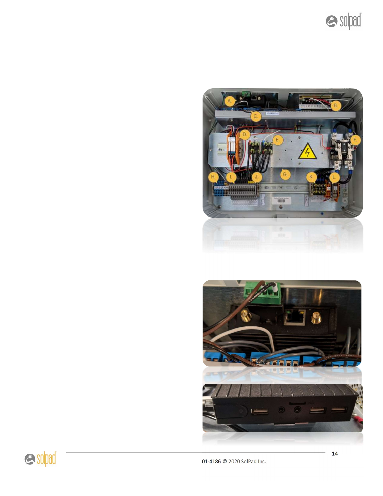
2.5 System Components and Descriptions
The SolPad 500HD series Energy Management Systems consist of the following components;
A. CPU
B. Power supply
C. MOTES
D. Slave Relays
E. 30-amp DPDT relays
F. 50-amp relay
G. 30-amp relays underneath mezzanine
H. Terminal block for CT’s
I. Terminal block for 20-amp relays
J. Terminal block for 30-amp relays
K. Terminal block for 50-amp relays
L. 4-amp breaker/AC power terminals
SolPad CPU – CompuLab
The CPU has ports on three of the four
sides. There will be an external IP labeled
on the side that doesn’t have any ports.
CPU features: Ethernet Port, USB ports,
Micro SD card slot, 4G antenna port,
RS485, Wi-Fi antenna, power input port

15
101 Metro Plaza • Suite 315 • San Jose, CA 95110 • (800) 801-4186 © 2020 SolPad Inc.
Power Supply
The Power Supply on the top-right of the panel inside the enclosure converts 120VAC to DC
voltages for the components in the system.
MOTES – Marvel of Tiny Engineering
The MOTEs are micro-controllers that exchange information with the CPU, and send
intermediate commands to the relays. The MOTEs are designated by a version number and
physical position. In the image below, the mote on the left is version “R1.1” (R for
Residential) and “/1” for the first position in the layout.
The first MOTE’s inputs (I-1, I-2, I-3, I-4) are used for the grid power CTs, while the second
MOTE is for the solar power or production CTs. Using jumpers, the input type can be
changed between 0-10V, 4-20mA, and 10K Ohms. The standard system uses 0-5V CTs, and
no jumper is required for any 0-5v input. The jumpers are installed on the left-hand side of
the MOTE.

16
101 Metro Plaza • Suite 315 • San Jose, CA 95110 • (800) 801-4186 © 2020 SolPad Inc.
The 8 outputs (O-1, O-2, O-3, O-4) between the motes are what send signals to the relays to
turn devices on/off. In Residential systems, only six outputs are used in conjunction with
relays to accommodate different load sizes, (O-1-3 on each.) The diagram below shows how
the layout is wired to cover the ranges.
4G High Gain Antenna / RS485 Adapter / Wi-Fi Antenna
The last three components are shown in the image below. The high gain antenna with
adapter that will be mounted on the exterior of the enclosure and the to the top SMA port,
the RS485 adapter, and Wi-Fi antenna mounted to the bottom SMA connector.

17
101 Metro Plaza • Suite 315 • San Jose, CA 95110 • (800) 801-4186 © 2020 SolPad Inc.
2.6 Relay Descriptions
20 Amp SPDT 240vac Relays
These relays are intended for use with 120v circuits landed on
breakers of 20-amps or less.
Each relay has two terminals: The lower is a ‘N.C.’ (normally closed)
terminal and the upper is a COM (common) terminal.
Each relay comes pre-wired to phoenix
terminals mounted on a DIN rail
Your load controller contains between 4-26 of
these relays depending on your model.
30 Amp DPDT 240vac Relays
The relay comes pre-wired to a set of phoenix terminals mounted on
a DIN Rail.
Each 30-amp relay has two positions on the terminal block (A and B).
A and B each have two terminals: The lower is a ‘N.C.’ (normally
closed) terminal and the upper is a COM (common) terminal.
To control one leg of a two-pole circuit (which
is usually all that is required) you’ll use the two
‘A’ terminals for that relay.
You can make use of the unused side (‘B’
terminals) to control a second circuit, but two
circuits on a single relay WILL BE CONTROLLED
TOGETHER.
18
101 Metro Plaza • Suite 315 • San Jose, CA 95110 • (800) 801-4186 © 2020 SolPad Inc.
50 Amp DPDT 240vac Open Frame Relays
When using the 50-amp relay to control an electric range,
both L1 and L2 need to be interrupted and run through the
relay.
FAILURE TO ADDRESS THE ITEMS BELOW COULD RESULT
IN THE RELAY HEATING UP AND FAILING.
All lug connections to the relay terminals MUST be
properly torqued AND VERIFIED AT INSTALLATION
COMPLETION
All lug set screws must be properly torqued AND
VERIFIED AT INSTALLATION COMPLETION
Both legs of the load must be connected to the relay.
Do not put different loads on one relay (IE: L1 from load
#1 on one leg of the relay, and L1 from Load 2 on the
other leg)

19
101 Metro Plaza • Suite 315 • San Jose, CA 95110 • (800) 801-4186 © 2020 SolPad Inc.
3. Installation
These instructions are intended only as GENERAL GUIDELINES to be used in conjunction with
local and national electrical and building codes. This unit should be installed and serviced by
qualified persons only. Install the system in 6 steps. Steps 3 - 5 can be performed
simultaneously, or in any order, however step 6 cannot be completed until after they are all
complete.
Installation Steps
1. Mount the enclosure
2. Source power for the system
3. Connectivity and Accessories
4. Installation of Current Transducers (CTs)
5. Connecting Devices to be Controlled
6. Power Up the Load Controller
7. System Verification, Test and Turn-up
The Installation technician will be required to supply some of the items necessary to
complete the installation as noted in the “Recommended Material” and Recommended
Tools sections.
**IMPORTANT NOTE: This Energy Management System is to be installed by a
professional electrician.
3.1 Mounting the Enclosure
Choose where to mount the enclosure.
The Enclosure is best mounted near:
The Source of Power
Where the CTs will be installed - Main Grid Power, Dedicated Loads, and Solar
Power CTs
Where devices to be controlled - Devices are typically intercepted for control at the
breaker panels but will sometimes require wire going to the device location.
The enclosure has four holes pre-drilled for mounting and should be used to secure the
enclosure according to local code and with the appropriate fasteners based on site
conditions.

20
101 Metro Plaza • Suite 315 • San Jose, CA 95110 • (800) 801-4186 © 2020 SolPad Inc.
After the Enclosure is mounted, go through all the terminals on the panel and make sure
they are all pushed in, the 16amp relays are properly seated, and then go to all the wire
connections and make sure none of them come loose by pulling the wire lightly.
3.2 Source Power for the System
The SolPad EMS needs an independent power source of
120VAC with a ground.
Power the load controller from a dedicated 15amp breaker
Terminate the conductors from the 15A breaker powering the
load controller as follows:
A. Land the ground wire on the ground lug (A in picture).
B. Land the Neutral (white) in the orange terminal labeled
‘N’ (B in picture)
C. Land the Line (black) in the orange terminal labeled ‘L’
(B in picture)
Make sure the wires can be lightly pulled on without coming
out.
D. Insert the 4A breaker as shown (C) in the grey terminal
block labeled LBK.
Keep the dedicated 15-amp breaker switched off until the
remaining installation steps are completed
3.3 Connectivity and Accessories
The SolPad Load Controller has several means of connection depending on the options
purchased.
1. 4G T-Mobile internal Cellular Modem (KORE secure-AWS servers) Preferred
2. Wi-Fi - Connect to the system through the local Wi-Fi independent of public
internet.
This manual suits for next models
3
Table of contents
Popular Controllers manuals by other brands


Honeywell
Honeywell CP-UL1012S installation instructions

Johnson Controls
Johnson Controls M9106-AG 2N0 Series installation instructions

AMFLOW
AMFLOW A6 quick start

Jandy
Jandy Jandy Pro Series Installation and operation manual

Velleman
Velleman Vellight LEDC25 user manual

Gardena
Gardena Watering Controller 6040 operating instructions


