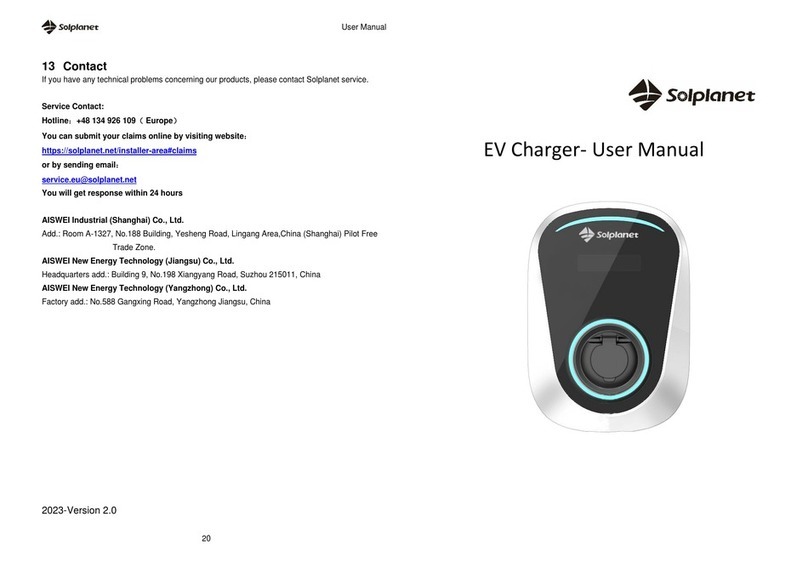
Solplanet SOL APOLLO Series User manual


User Manua UM0027_ SOL APOLLO Series 7.4-22K_EN_V01_0822 1
Thank you for choosing our Solplanet Smart EV Charger.
The Solplanet Smart EV Charger is an AC power charging station, it supplies
AC power to charge electric vehicles.
The EV charger is suitable for outdoor and indoor use such as garages,
carports underground car parks, apartment blocks, hotel parking lots and other
areas where an EV charger may be suitable.
The EV charger can be operated with an RFID card, our Ai-charging APP or
an NFC authorized smart device.
This manual describes the installation, commissioning, maintenance and
troubleshooting of the following SOL APOLLO Series’s EV chargers:
SOL7.4H, SOL11H, SOL22H.
Please read and follow the instructions in this manual carefully.

2 User Manua UM0027_ SOL APOLLO Series 7.4-22K_EN_V01_0822
Table of Contents
1 Notes on this Manual................................................................................... 4
1.1 Area of validity....................................................................................... 4
1.2 Target group .......................................................................................... 4
1.3 Symbols used in this manual............................................................... 5
2 Safety............................................................................................................. 6
2.1 Intended use .......................................................................................... 6
2.2 Safety standards.................................................................................... 6
2.3 Important safety information................................................................ 6
2.4 Symbols on label................................................................................... 8
2.5 Basic safety protection......................................................................... 8
3 Scope of delivery ......................................................................................... 9
4 Overview ..................................................................................................... 10
4.1 Overview of the product ..................................................................... 10
4.2 System overview with power management ...................................... 12
4.3 LED Indicators ..................................................................................... 12
4.4 Interfaces.............................................................................................. 13
4.5 Special Features.................................................................................. 14
5 Mounting..................................................................................................... 16
5.1 Planning the Installation..................................................................... 16
5.2 Site Requirements............................................................................... 16
5.3 Selecting the mounting location........................................................ 18
5.4 Mounting the product.......................................................................... 19
6 Commissioning and operation ................................................................. 35

User Manua UM0027_ SOL APOLLO Series 7.4-22K_EN_V01_0822 3
6.1 Mechanical checks.............................................................................. 35
6.2 Electrical checks ................................................................................. 36
6.3 Establish a connection to the Ai-charging app................................ 36
6.4 Activate the RFID card ........................................................................ 36
6.5 Charging EV......................................................................................... 37
6.6 Stop charging ...................................................................................... 39
7 Cleaning and Maintenace.......................................................................... 41
8 Troubleshooting......................................................................................... 42
9 Technical data ............................................................................................ 46
9.1 Inputs and Outputs (AC) .................................................................... 46
9.2 General data......................................................................................... 47
9.3 Safety regulations ............................................................................... 48
10 Recycling and disposal ........................................................................... 49
11 EU declaration of conformity.................................................................. 49
12 Contact...................................................................................................... 50

4 User Manua UM0027_ SOL APOLLO Series 7.4-22K_EN_V01_0822
1 Notes on this Manual
General Notes
The Solplanet Smart EV Charger is an AC power charging station, it supplies
AC power to charge electric vehicles.
1.1 Area of validity
This manual describes the mounting, installation, commissioning, operation
and maintenance of the following SOL APOLLO EV chargers:
⚫SOL7.4H
⚫SOL11H
⚫SOL22H
The series listed above is equipped with a variety of interfaces, please check
the technical specifications in section 9 Technical data to confirm the
interfaces that are available on the EV charger.
1.2 Target group
This document is intended for qualified persons and end users. Only qualified
persons are allowed to perform the activities marked in this document with a
warning symbol " ". The tasks with no " " symbol may also be
performed by end users.
Qualified persons must have the following skills:
⚫Knowledge of how the EV charger works and is operated;
⚫Identify the hazards (in terms of a risk assessment), relevant to the
working conditions on the site;
⚫Trained in the installation and commissioning of electrical devices and
installations;
⚫Knowledge of all applicable laws, standards and directives;
⚫Knowledge of and compliance with this document and all safety
information.

User Manua UM0027_ SOL APOLLO Series 7.4-22K_EN_V01_0822 5
1.3 Symbols used in this manual
The safety precautions and general information are used in this manual as
follows:
DANGER indicates a hazardous situation which, if not avoided, will
result in death or serious injury.
WARNING indicates a hazardous situation which, if not avoided, can
result in death or serious injury.
CAUTION indicates a hazardous situation which, if not avoided, can
result in minor or moderate injury.
NOTICE indicates a situation which, if not avoided, can result in
property damage.
INFORMATION provides tips which are valuable for the optimal
installation and operation of the EV charger.

6 User Manua UM0027_ SOL APOLLO Series 7.4-22K_EN_V01_0822
2 Safety
2.1 Intended use
The EV charger is an AC charging device.
The EV charger may automatically adjust its output power during operation due
to non-ideal conditions e.g., extremely high ambient temperatures.
The EV charger can only be operated in accordance with the information
provided in the enclosed documentation and with the locally applicable laws,
regulations and standards. Any other application may cause personal injury or
property damage.
The EV charger must be used as a stationary device.
All components of the EV charger must remain within their permitted operating
ranges at all times.
Adapters, extension cables and conversion cables must not be used with
either version of the EV chargers.
2.2 Safety standards
SOL APOLLO EV chargers comply with the EU Low-Voltage Directive
2014/35/EU and the EMC Directive 2014/30/EU. The EV charger also
complies with the requirement for safety and EMC in European market. They
are labeled with the CE mark.
For more information about certificates in other countries and regions, please
visit website ( www.solplanet.net ).
2.3 Important safety information
Before installing, operating or maintaining this product, it is important to read
and ensure that the contents of the following Guide are fully understood.
Failure to follow all the specified instructions and procedures, will invalidate
the warranty and as such Solplanet will not be liable for any claims for
compensation.

User Manua UM0027_ SOL APOLLO Series 7.4-22K_EN_V01_0822 7
Danger to life due to electric shock when live components or cables
are touched
• Do not open the EV charger under load or when it is not electrically
isolated.
•Do not use the EV charger if it is damaged.
•Do not extend the charging cable with an extension lead.
•Do not touch or insert foreign objects into the EV charger socket or the
cable plug.
•Do not install the EV charger near flammable, explosive, or combustible
materials.
Risk of injury due to electric shock
•All work on the equipment must only be carried out by qualified personnel
who have read and fully understood all safety information and installation
requirements contained in this manual.
•The EV charger must be out of reach from children.
•The EV charger must be connected to a protective earth conductor.
•The electrical installation must comply with all applicable local safety
requirements, standards and guidelines.
•No modifications , not limited to mechanical or electrical, must be made
to the EV charger.
•Components should not be changed or replaced by the end-user or
unqualified personnel.
•Do not use conversion adapters or cord extension sets with the EV
charger.

8 User Manua UM0027_ SOL APOLLO Series 7.4-22K_EN_V01_0822
2.4 Symbols on label
Symbol
Explanation
Risk of danger, warning and caution
Safety information, important for human safety. Failure to
observe the safety information in this manual may result in
injury or death.
Be ware of high voltage and operating current.
The EV charger operates at high voltage and current. Work
on the EV charger must only be carried out by skilled and
authorized electricians.
Certified safety
The product is TUV-tested and complies with the
requirements of the EU Equipment and Product Safety Act.
CE mark.
The EV charger complies with the requirements of the
applicable CE guidelines.
Do not dispose of the EV charger with household waste.
For more information on disposal, please refer to Section 10
“Recycling and disposal”.
Refer to the manual accompanying the EV charger.
2.5 Basic safety protection
The EV charger provides the following safety protection functions:
1) Over-voltage, under-voltage protection;
2) Over-frequency, under-frequency protection;
3) Over-current protection;
4) Residual current monitoring;
5) Grounding conductor monitoring;
6) Relay fault monitoring;
7) Phase lost monitoring;
8) Over-temperature monitoring.

User Manua UM0027_ SOL APOLLO Series 7.4-22K_EN_V01_0822 9
3 Scope of delivery
Inspect the product packaging for any external visible damage and ensure that
all items in the table below have been included. Contact your supplier if the
accessories delivered are incomplete or if the EV charger or accessories show
signs of damage.
A
B
C
D
E
F
G
H
I
Object
Description
Quantity
A
EV charger
1 piece
B
Rubber seal kit
1 set
C
Screw accessory kit:
Wall anchors and hexagon bolts (3×)
M4×10 mm screw (2×)
M4×6 mm screw (1×)
ST3×10 mm screw (2×)
1 set
D
Mounting template
1 piece
E
RFID card
3 pieces
F
AC Input cable fastener
1 piece
G
Energy meter (Optional)
1 piece
H
Cable holder (for cable version)
1 piece
I
Quick installation guide
1 piece

10 User Manua UM0027_ SOL APOLLO Series 7.4-22K_EN_V01_0822
4 Overview
4.1 Overview of the product
Socket Version
Figure 1: Overview of the socket version
Position
Description
A
RFID / NFC Reader
Area for RFID card scanning or for use with NFC authorized
smart devices
B
LED strip
Indicates the operating state of the EV charger.
C
Socket
D
Input cable gland
E
Communication cable gland
F
Type label
G
QR code
H
Knockout entry reserved for input AC cable

User Manua UM0027_ SOL APOLLO Series 7.4-22K_EN_V01_0822 11
Cable Version
Figure 2: Overview of the cable version
Position
Description
A
RFID / NFC Reader
Area for RFID card scanning or for use with NFC authorized
smart devices
B
LED strip
Indicates the operating state of the EV charger.
C
Charging plug
D
Input cable gland
E
Communication cable gland
F
Type label
G
QR code
H
Charging plug cable
I
Knockout entry reserved for input AC cable

12 User Manua UM0027_ SOL APOLLO Series 7.4-22K_EN_V01_0822
4.2 System overview with power management
The SOL APOLLO EV charger provides the Load Balance function for users
when installed together with an energy meter. This function automatically
adjusts the charging power depending on the power flow within the system,
When the homes’power consumption is stable and the PV power increases,
the EV charger charging power will increase accordingly. The increase of power
will be no greater than 32 A and can be also limited by the EV on-board charger
(OBC).
Figure 3: System Layout Overview (example with SOL7.4H)
4.3 LED Indicators
The EV charger is equipped with one LED strip which provides information
about the various operating states represented by four colours.

User Manua UM0027_ SOL APOLLO Series 7.4-22K_EN_V01_0822 13
Explanation of the different light signals:
EV Charger Status
LEDs Status
Standby
Green - solid
- Connected to vehicle and ready to
charge
- End of charging
- Charging paused
Ice blue - solid
Charging
Blue - pulsing
Charging (with full green power)
Green - pulsing
Charging (mix of grid/green power)
Ice blue - pulsing
E-LOCK
Yellow-solid
Fault
Red - blinking
Firmware update
Purple - blinking
RFID card identification succeeded
(with operation)
Ice blue - blinking (once)
RFID card binding succeeded
Ice blue - blinking (twice)
RFID card identification succeeded
(without operation)
Purple - blinking (once)
Invalid RFID card
Purple - blinking (twice)
Binding RFID cards over limit
Purple - blinking (three times)
4.4 Interfaces
The SOL APOLLO EV charger is equipped with the following interfaces and
functions:
WLAN
The EV charger is supplied with WLAN interface as standard.
BLE
The EV charger is supplied with a BLE (identifiable by the EV charger serial
number) interface as standard. The BLE connection facilitates a point-to-point

14 User Manua UM0027_ SOL APOLLO Series 7.4-22K_EN_V01_0822
connection between the EV charger and a smart mobile device.
Ethernet (optional)
The EV charger is supplied with Solplanet Speedwire as optional
configuration, which is a type of communication based on the Ethernet
standard. Solplanet Speedwire is designed for a data transfer rate of 100
Mbps and enables optimum communication between the EV charger and the
Ai-charging app via a router.
4G (optional)
The EV charger is supplied with a 4G module which allows an LTE-
FDD/WCDMA/GSM network connection link in situations where there is no
WLAN or ethernet available.
NFC Authorization
This function activates the EV charger by detecting the digital key stored in a
smart phone or smart device. Check whether the smart phone is compatible
with NFC and NFC function which is required to be activated. Follow your
smart phone’s NFC instructions and place the authorized RFID card on the
phone’s NFC area, and copy the card data onto your smart phone. Please
note that this function does not support iPhone or other apple products due to
Apple’s restrictions for NFC.
4.5 Special Features
Dynamic load balancing (requires an energy meter)
Dynamic load balancing ensures you never overdraw your property’s power
capacity by balancing the power consumption between your EV charger and
other electrical household appliances. The system measures the power
consumption of the house by the energy meter and allocates all available
power to your EV. The charge power is continuously adjusted, in response to
changes in generation or power consumption elsewhere around the house.
You can maintain a safe and convenient charging at all times while keeping

User Manua UM0027_ SOL APOLLO Series 7.4-22K_EN_V01_0822 15
costs low.The EV charger may prioritise the use of excess solar power
generated by a PV system, if available, rather than the grid power.

16 User Manua UM0027_ SOL APOLLO Series 7.4-22K_EN_V01_0822
5 Mounting
5.1 Planning the Installation
5 Qualified Person
Installing and connecting the product must be done by a qualified electrician.
Laws and regulations, relevant to the country of installation, regarding the
safety of persons, animals, and property must be observed. A typical planning
procedure may include but are not limited to the following:
1. Calculate the existing electrical load to determine the maximum operating
current.
2. Calculate the appropriate cable size with respect to distance to minimize
voltage drops.
3. Obtain any necessary permits from the local authority that has jurisdiction
and confirm that the follow-up inspection has been scheduled by a
qualified electrician after the installation is complete
4. Use only copper conductors.
5. Use conductors that are sized in accordance with local wiring regulations.
The selected cable gauge must be able to sustain periods of a constant
load up to 16A / 32A.
6. Each unit should be connected to an appropriately sized circuit breaker.
7. Knowledge of the current capacity of the site (in amperes).
5.2 Site Requirements
1. Ensure the product is installed out of reach from children.
2. Ensure appropriate access to the product for installation and
maintenance.
3. Ensure there is adequate heat dissipation by observing the minimum
clearance to walls, other EV chargers or objects:

User Manua UM0027_ SOL APOLLO Series 7.4-22K_EN_V01_0822 17
The installation height from the ground is between 1400 mm and 1600 mm
1400-1600mm
4. The ambient temperature below 40°C is recommended (to ensure optimal
operation).
5. It is recommended to mount the product under a shaded site of the building
or to mount a sun shield above the product.
6. Avoid exposing the product to direct sunlight, rain and snow to ensure
optimal operation and an extended service life.
Direction
Min. Clearance (mm)
above
200
below
200
sides
200

18 User Manua UM0027_ SOL APOLLO Series 7.4-22K_EN_V01_0822
7. The mounting method, location and surface must be suitable for the
products weight and dimensions.
8. If mounted in a residential area, we recommend mounting the product on
a solid surface. Plasterboard and similar materials are not recommended.
9. Do not place any objects on the product.
5.3 Selecting the mounting location
1. Mount the product vertically or tilted backward by a maximum of 15°.
2. Never mount the product tilted forward or sideways.
3. Never mount the product horizontally.
4. Mount the product at eye level to make it easy to operate and to read the
LED strip.
5. The electrical connection area must point downwards.
Danger to life due to fire or explosion
• Despite careful construction, if installed incorrectly or mounted in
unsuitable locations, electrical devices can cause fires which may
result in death or serious injury.
• Do not mount the product on flammable construction materials.
• Do not mount the product in areas where flammable materials are
stored.
• Do not mount the product in areas where there is a risk of explosion.

User Manua UM0027_ SOL APOLLO Series 7.4-22K_EN_V01_0822 19
5.4 Mounting the product
Removing the decorative cover
1. Remove the bottom screw (A) on the flat workbench.
2. It is recommended to start at the bottom of enclosure (C) when removing
the decorative cover (B).
Figure 4
Drill three Φ10 mm holes at a depth of approximately 70 mm for the
mounting screws
1. Hold the mounting template (A) against the wall and ensure that the
installation is level by using the spirit level.
2. Mark the location for three mounting holes (B).
3. Drill three mounting holes (B).
4. Insert the wall plugs (C) into the mounting holes (B).
Figure 5
Other manuals for SOL APOLLO Series
2
This manual suits for next models
9
Table of contents
Other Solplanet Batteries Charger manuals

