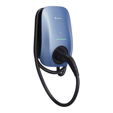
Solplanet SOL APOLLO Series User manual

SOL7.4H-WP / SOL7.4H-WS / SOL7.4H-WSS / SOL11H-WP /
SOL11H-WS / SOL11H-WSS / SOL22H-WP / SOL22H-WS /
SOL22H-WSS
SOL APOLLO Series

TABLE OF CONTENTS
Hızlı Kurulum Kılavuzu
Türkçe 122
Snabbinstallationsguide 111
Svenska
Guia de Instalação Rápida 100
Português
Instrukcja szybkiej instalacji 89
Polski
Hurtiginstallasjonsveiledning 78
Norsk
Gyors telepítési útmutató 56
Magyar
Italiano Guida rapida all'installazione 45
Manuel d'installation rapide 34
Français
Español Guía de instalación rápida 23
Snelle installatiehandleiding 67
Nederlands
Deutsche Schnellinstallationsanleitung 12
Quick Installation Guide
English 1

Before installing, operating or maintaining this product, it is important to read and ensure that the contents
of the following Quick Installation Guide are fully understood. Failure to follow all the specied instructions
and procedures, will invalidate the warranty and as such Solplanet will not be liable for any claims for
compensation.
• Do not open the EV charger under load or when it is not electrically isolated.
• Do not use the EV charger if it is damaged.
• Do not extend the charging cable with an extension lead.
• Do not touch or insert foreign objects into the charger socket or the cable plug.
• Do not install the charger near ammable, explosive, or combustible materials.
• All work on the equipment must only be carried out by qualied personnel who have read and
fully understood all safety information and installation requirements contained in this guide.
• The EV charger must be out of reach from children.
• The EV charger must be connected to a protective earth conductor.
• The electrical installation must comply with all applicable local safety requirements, standards and
guidelines.
• No modications, not limited to mechanical or electrical, must be made to the EV charger.
• Components should not be changed or replaced by the end-user or unqualied personnel.
• Danger to life due to re or explosion.
• Despite careful construction, if installed incorrectly or mounted in unsuitable locations, electrical
devices can cause res. This can result in death or serious injury.
• Do not mount the EV charger in areas containing highly ammable materials or gases.
• Do not mount the EV charger in potentially explosive atmospheres.
I. Safety Instructions
II. Mounting Environment
Requirements for mounting location:
• Please avoid exposing the EV charger to direct sunlight.
• The surface for mounting of the EV charger must be made of a non-ammable material.
• It is recommended that the location oer protection against rain, running water or other liquids.
• The location must oer sucient air ventilation.
• The installation surface area requires at least 230 mm x 360 mm.
1
ENGLISH

III. Scope of delivery
The installation height is between 1400 and 1600
mm (from the oor to the bottom of the EV charger
housing).
1400-1600mm
The installation location must be freely accessible.
Energy meterX1
230mm
360mm
The installation requires at least
an area of 230 mm x 360 mm.
1
A solid and an even support
surface, e.g. concrete or masonry,
must be available for mounting.
2
A minimum clearance of 200 mm
from other equipment or objects
must be maintained.
3
4 5
2ENGLISH

IV. EV Charger Mounting
Removing the decorative cover
Inserting the upper mounting
screws
Installing the EV charger on the
wall
Drill three Φ10 mm holes at a
depth of approximately 70 mm for
the mounting screws
1. Remove the bottom screw (A) on the at
workbench.
2. It is recommended to start at the bottom of
enclosure (C) when removing the decorative
cover (B).
1. Install the upper mounting screws (A) in the upper
holes (B). The recommended torque is 4.4 Nm.
2. Ensure the screw protrudes at a length X out from
the wall. The length of X is recommended to be 3
mm (0.12inch).
1. Place the openings (A) over the upper mounting
screws (B).
The upper mounting screws support the EV charger.
1. Hold the installation template (A) against the
wall and ensure the installation is level by using a
spirit level.
2. Mark the location for the three mounting holes
(B).
3. Drill three mounting holes (B).
4. Insert the wall plugs (C) into the mounting
holes (B).
12
3 4
ENGLISH 3

V. AC connection
Removing the top cover
1. Remove all eight screws from enclosure, no need to
take out anti drop screws from top cover(B).
2. Remove the top cover (B) (Take care with the cable
which connect to the top cover on the socket version
of the EV charger) .
Installing the inner screw on the
bottom cover
1. Thread the screw (A) through the sealing rubber
(B) located at the sealing rubber accessory. Then
install the mounting screw (A) to secure the
enclosure to the surface. The recommended torque
is 4.4 Nm.
Installing the incoming AC supply cable
There are two options for installing the incoming AC supply cable.
Option 1
Through the cable gland (A) located on the bottom
of the enclosure.
Option 2
Drilling a hole through the rubber seal located on
the rear of the enclosure (A).
• All electrical installations must be done in accordance with all local and national rules.
• Ensure that all power sources have been electrically isolated before any electrical
terminations have been made.
5 6
ENGLISH
4

1. Strip the incoming AC supply cable as shown below, and crimp the copper wire to the appropriate
OT terminal (according to DIN 46228-4, to be provided by the customer).
2. Install the incoming AC supply cable.
Option 1
Remove the cable gland from the bottom of the
enclosure.
Thread the incoming AC supply cable through the
cable gland, loosen the nut (A).
Install the cable gland on the bottom of the
enclosure, fasten the nut (B). And then fasten the
nut (A).
Object
Description
Value
A External diameter 18-21mm
B Copper conductor cross-section 4-16mm2
C Stripping length of the insulated conductors 12mm
D Stripping length of the cable outer sheath 75mm
Note: The PE conductor is at least 5mm longer than the L and N conductors.
Single phase
Three phase
Object Description Value
A External diameter 18-21mm
B Copper conductor cross-section 4-16mm2
C Stripping length of the insulated conductors 12mm
D Stripping length of the cable outer sheath 75mm
Note: The PE conductor is at least 5mm longer than the L and N conductors.
A
1
2
3
ENGLISH 5

Option 2
According to the diameter of the incoming AC
supply cable, select the appropriate circle on the
rubber seal to penetrate.
Thread the input cable through the rubber seal.
3. Secure the cable (A) with the cable clip (B). Install the two screws (C) to secure the cable.
(For Option 1)
Install the rubber seal (A) on the rear of the
enclosure (B).
A
A
B
1
2 3
ENGLISH
6

VI. Communication setup
Single phase
Ethernet/LAN connection
Loosen the cable clamps (A) of the terminal block.
Insert the cables into the terminal block (B).
Connect the below wires:
1. AC input wire (C)
2. Neutral wire (D)
3. Earthing wire (E)
1. The ethernet cable type should be 100BaseTx with an RJ45 plug, The ethernet (RJ45) terminal pin
assignment is as the table below (For the Option version with ethernet).
Energy meter connection
2. RS485 cable pin assignment is as the table below, a standard Ethernet cable is recommended. Strip the
wire as shown in the gure, and crimp the copper wire to the appropriate OT terminal (according to DIN
46228-4, provided by the customer) if the cable is multi strand exible conductor. The other end of the cable
should be connected to the corresponding terminals of the energy meter, please refer to the energy meter
manual for further information.
Three phase
Loosen the cable clamps (A) of the terminal block.
Insert the cable into the terminal block (B). Connect
the below wires:
1. L1 (C)
2. L2 (F)
3. L3 (G)
4. Neutral wire (D)
4.Terminate the incoming AC supply cable.
FG
Pin Name Description
1 TX+ Tranceive data+
2 TX- Tranceive data-
3 RX+ Receive data+
4 N/C Not connected
5 N/C Not connected
6 RX- Receive data-
7 N/C Not connected
8 N/C Not connected
ENGLISH 7

3. Remove the middle cable gland (A) at the bottom
of the enclosure.
4. Remove the external nut (A), then remove the
blocking rubber (B). Next, insert the ethernet cable
into the hole (C). Repeat the similar step for the
RS485 cable installation.
5. Assemble the cable gland and loosen the external
nut (A).
7. Put the RJ45 plug of the Ethernet cable in the
Ethernet RJ45 socket (A). Put the RS485 cable
in the RS485 socket (B).
CN310Pin Name Description
1 RS485A-1 For communication with an energy
meter
2 RS485B-1
3 RS485A-2 For communication withan energy
meter
4 RS485B-2
A
A
B
C
A
6. Install the cable gland at the bottom of the
enclolsure and fasten the nut (B), afterwards fasten
the nut (A).
A
B
A
B
ENGLISH
8

VII. Commissioning
Insert 4G SIM card (4G Option)
1. Insert the SIM card (A) into the sim card holder (B). Ensure the position of the connection points are
correct.
Warning: Only use this commissioning procedure together with the Ai-Charging app for
domestic applications. For all the other methods of commissioning, please contact your
local representative of the manufacturer.
The charger turns ON and a series of self-checks will begin, to ensure the charger works correctly and safety.
If the charger passes the self-check, the colour of the LED will illuminate green.
If the charger fails the self-check, the colour of LED will illuminate red.
3.To setup the EV charger:
Open and log into the Ai-Charging app.
Initial set up.
Find the EV Charger on the app.
Once the initial setup is done:
Adjust the parameter setting accordingly for the charger.
Connect your electrical vehicle to the charger.
Turn on the Charger via the app or by swiping the RFID card.
Check the charging current and status via the app.
(For Wi-Fi set-up, please refer to the Ai-charging app manual that can be found on our website).
1. To download the Ai-Charging app, please scan the QR code located on the last page of this guide.
The app is compatible with Android versions later than 8.0, and iOS mobile versions 12.1 or later.
2. Close the circuit breaker that supplies the power to the EV charger.
Warning:
Hazardous voltage
Be careful when you work with electricity
ENGLISH 9

VIII. Access to parts
Removing the decorative cover
1. Remove the following parts:
Screw (A)
Decorative cover (B)
Installing the decorative cover
1. Install the following parts:
Screw (A)
Decorative cover (B)
Removing the Top cover
1.Remove the following parts:
Screws (A)
Top cover (B)
Installing the top cover
1.Install the following parts:
Screws (A)
Top cover (B)
ENGLISH
10

IX. EU Declaration of Conformity
X. Contact
Within the scope of the EU directives:
- Electromagnetic compatibility 2014/30/EU
(L 96/79-106 ,March 29, 2014)(EMC)
- Low voltage directive 2014/35/EU (L 96/357-374 ,March 29, 2014)(LVD)
- Radio equipment directive 2014/53/EU (L 153/62-106 ,May 22, 2014)(RED)
AISWEI New Energy Technology (Yangzhong) Co., Ltd. conrms herewith that the EV chargers
mentioned in this document are in compliance with the fundamental requirements and
other relevant provisions of the above mentioned directives.
The entire EU Declaration of Conformity can be found at www.solplanet.net.
If you have any technical problems with our products, please contact our service.
Provide the following information when you initiate a service request:
- Charger device type
- Charger serial number
- Error code (LED ash code / status)
- Mounting location
- Proof of purchase
Service Contact:
Website: https://solplanet.net/contact-us/
You can submit your claims online by visiting our website:
https://solplanet.net/claims/
You will receive a response within 24 hours.
AISWEI New Energy Technology (Yangzhong) Co, Ltd.
Add: No.588 Gangxing Road, Yangzhong Jiangsu, China
Web: https://solplanet.net
ENGLISH 11
Android QR code IOS QR code

Bevor Sie dieses Produkt installieren, in Betrieb nehmen oder warten, sollten Sie unbedingt die folgende
Schnellinstallationsanleitung lesen und sicherstellen, dass Sie den Inhalt vollständig verstanden haben. Die
Nichtbeachtung der angegebenen Anleitungen und Verfahren führt zum Erlöschen der Garantie. Infolgedes-
sen erlöschen jegliche Schadensersatzansprüche gegenüber Solplanet.
• Önen Sie die EV-Ladestation nicht unter Spannung oder wenn sie nicht elektrisch isoliert ist.
• Verwenden Sie niemals eine beschädigte EV-Ladestation.
• Verlängern Sie das Ladekabel nicht mit einem Verlängerungskabel.
• Berühren Sie die Ladebuchse oder den Kabelstecker nicht und stecken Sie keine Fremdkörper hinein.
• Installieren Sie die Ladestation nicht in der Nähe von entzündlichen, explosiven oder brennbaren
Materialien.
• Alle Arbeiten an dem Gerät dürfen nur von qualiziertem Personal durchgeführt werden, das alle
in dieser Anleitung enthaltenen Sicherheitshinweise und Installationsanforderungen gelesen und
verstanden hat.
• Die EV-Ladestation muss sich außerhalb der Reichweite von Kindern benden.
• Die EV-Ladestation muss mit einem Schutzleiter verbunden werden.
• Die elektrische Installation muss allen lokalen geltenden Sicherheitsvorschriften, Normen
und Richtlinien.
• Es dürfen keine Änderungen, weder mechanisch noch elektrisch, an der Ladestation vorgenommen
werden.
• Endverbraucher oder nicht qualiziertes Personal dürfen keine Komponenten austauschen oder
ersetzen.
• Lebensgefahr wegen Feuer oder Explosion.
• Trotz sorgfältigster Konstruktion besteht bei fehlerhafter Installation oder Montage an einem
ungeeigneten Ort die Gefahr, dass elektrische Geräte Feuer fangen können. Dann besteht
Lebensgefahr oder die Gefahr von schwerwiegenden Verletzungen.
• Montieren Sie die EV-Ladestation nicht in Bereichen mit hochentzündlichen Materialien oder Gasen.
• Montieren Sie die EV-Ladestation nicht in potenziell explosionsgefährdeten Atmosphären.
•Nie należy montować ładowarki EV w miejscach zagrożonych wybuchem.
I. Sicherheitshinweise
II. Montageumgebung
Anforderungen an den Montageort:
• Setzen Sie die EV-Ladestation nicht direktem Sonnenlicht aus.
• Die Oberäche für die Montage der EV-Ladestation muss aus einem nicht entzündlichen Material bestehen.
• Es wird empfohlen, dass der Ort Schutz vor Regen, ablaufendem Wasser und anderen Flüssigkeiten bieten
muss.
• Diese Position muss ausreichende Belüftung bieten.
• Die Montageäche hat eine Größe von mindestens 230 mm x 360 mm.
Deutsche
12

III. Lieferumfang
Die Installationshöhe (ab Fußboden bis zur
Unterseite des EV-Ladestationsgehäuses) beträgt
1400 bis 1600 mm.
1400-1600mm
Der Installationsort muss frei zugänglich sein.
230mm
360mm
Die Installation erfordert
mindestens eine Fläche von 230
mm x 360 mm.
1
Für die Montage ist eine feste und
ache Stützäche vorzusehen,
beispielsweise Beton oder
Mauerwerk.
2
Es ist ein Mindestabstand von 200
mm zu anderen Ausrüstungen
oder Gegenständen einzuhalten.
3
4 5
EV-Ladestation X1
Schnellinstallationsanleitung
Dichtungsgummi-
Zubehör X1
Schrauben-
Zubehör X1
Installationsschablone X1 Karta RFID X3
Kabelhalter X1
(für Kabelversion)
Clip für AC-
Eingangskabel X1
Intelligenter
Zähler X1
(optional)
Deutsche 13

IV. Montage EV-Ladestation
Entfernen der Zierabdeckung
Einsetzen der oberen Befesti-
gungsschrauben
Installieren der EV-Ladestation an
der Wand
Bohren Sie drei Φ10 mm große
Löcher in einer Tiefe von etwa 70
mm für die Befestigungsschrau-
1. Entfernen Sie die untere Schraube (A) auf der
achen Werkbank.
2. Es wird empfohlen, beim Entfernen der
Zierabdeckung (B) an der Unterseite des
Gehäuses (C) zu beginnen.
1. Setzen Sie die oberen Befestigungsschrauben (A)
in die oberen Löcher (B) ein. Das empfohlene
Drehmoment beträgt 4,4 Nm.
2. Stellen Sie sicher, dass die Schraube um eine
Länge X aus der Wand herausragt. Es wird
empfohlen, dass die Länge X 3 mm (0,12 Zoll)
beträgt.
1. Setzen Sie die Önungen (A) über die oberen
Befestigungsschrauben (B).
Die oberen Befestigungsschrauben stützen die
EV-Ladestation.
1. Halten Sie die Montageschablone (A) an die
Wand und stellen Sie mit einer Wasserwaage sicher,
dass die Installation eben ist.
2. Markieren Sie die Position für die drei
Montagelöcher (B).
3. Bohren Sie drei Befestigungslöcher (B).
4. Stecken Sie die Dübel (C) in die Montagelöcher
(B).
12
34
Deutsche
14

V. AC-Anschluss
Entfernen der oberen Abdeckung
1. Entfernen Sie alle acht Schrauben des Gehäuses.
Die Schrauben der oberen Abdeckung (B) müssen
nicht entfernt werden.
2. Entfernen Sie die obere Abdeckung (B) (Seien Sie
vorsichtig mit dem Kabel, das an der oberen
Abdeckung der Steckdosenversion der EV-Ladesta-
tion angeschlossen ist).
Einsetzen der inneren Schraube an
der unteren Abdeckung
1. Führen Sie die Schraube (A) durch das Dichtungs-
gummi (B), das sich am Dichtungsgummi-Zubehör
bendet. Bringen Sie dann die Befestigungss-
chraube (A) an, um das Gehäuse an der Oberäche
zu befestigen. Das empfohlene Drehmoment
beträgt 4,4 Nm.
Installieren des eingehenden AC-Versorgungskabels
Es gibt zwei Optionen für die Installation des eingehenden AC-Versorgungskabels.
Option 1
Durch die Kabelverschraubung (A) an der Unterseite
des Gehäuses.
Option 2
Bohrung durch die Gummidichtung auf der
Rückseite des Gehäuses (A).
• Alle elektrischen Installationen müssen in Übereinstimmung mit allen lokalen und nationalen
Vorschriften durchgeführt werden.
• Stellen Sie sicher, dass alle Stromquellen elektrisch isoliert sind, bevor Sie elektrische .
56
Deutsche 15

1. Isolieren Sie das eingehende AC-Versorgungskabel wie unten gezeigt ab, und crimpen Sie den Kupferdraht an
die entsprechende
OT-Klemme (gemäß DIN 46228-4, bauseits).
2. Installieren Sie das eingehende AC-Versorgungskabel.
Option 1
Entfernen Sie die Kabelverschraubung an der
Unterseite des Gehäuses.
Führen Sie das eingehende AC-Versorgungskabel
durch die Kabelverschraubung, lösen Sie die Mutter
(A).
Bringen Sie die Kabelverschraubung an der
Unterseite des Gehäuses an und befestigen Sie die
Mutter (B). Und ziehen Sie dann die Mutter (A) an.
Element Opis
A Średnica zewnętrzna 18-21mm
B Przekrój przewodu miedzianego 4-16mm2
C
Długość ściągania izolacji z izolowanych przewodów
12mm
D Długość ściągania powłoki zewnętrznej kabla 75mm
Uwaga: Żyła PE jest dłuższa o co najmniej 5 mm od przewodów żył L i N.
Einphasig
Dreiphasig
Element Opis Wartość
A Średnica zewnętrzna 18-21mm
B Przekrój przewodu miedzianego 4-16mm2
C
Długość ściągania izolacji z izolowanych przewodów
12mm
D A kábel külső burkolatának lecsupaszítási hossza 75mm
Uwaga: Żyła PE jest dłuższa o co najmniej 5 mm od przewodów żył L i N.
A
1
2
3
Wartość
Deutsche
16

Option 2
Wählen Sie je nach Durchmesser des eingehenden
AC-Versorgungskabels den entsprechenden Kreis
auf der Gummidichtung aus, den Sie durchstechen
möchten.
Führen Sie das Eingangskabel durch die Gummid-
ichtung.
3. Sichern Sie das Kabel (A) mit der Kabelklemme (B). Bringen Sie die beiden Schrauben (C) an, um das Kabel
zu sichern.
(Für Option 1)
Bringen Sie die Gummidichtung (A) auf der
Rückseite des Gehäuses (B) an.
A
A
B
1
2 3
Deutsche 17

VI. Kommunikationseinrichtung
Einphasig
Ethernet/LAN-Verbindung
Lösen Sie die Kabelklemmen (A) der Klemmleiste.
Führen Sie die Kabel in die Klemmenleiste (B) ein.
Schließen Sie die folgenden Drähte an:
1. AC-Eingangskabel (C)
2. Neutralleiter (D)
3. Erdungsdraht (E)
1. Der Typ des Ethernet-Kabels sollte 100BaseTx mit einem RJ45-Stecker sein. Die Anschlussbelegung des
Ethernet (RJ45) ist wie in der Tabelle unten angegeben (für die Option-Version mit Ethernet).
Anschluss Energiezähler
2. Die Pinbelegung des RS485-Kabels entspricht der nachstehenden Tabelle. Es wird ein Standard-Ether-
net-Kabel empfohlen. Isolieren Sie das Kabel wie in der Abbildung gezeigt ab, und crimpen Sie den Kupfer-
draht an die entsprechende OT-Klemme (gemäß DIN 46228-4, die vom Kunden bereitgestellt wird), wenn es
sich um ein mehradriges exibles Kabel handelt. Das andere Ende des Kabels sollte an die entsprechenden
Klemmen des Energiezählers angeschlossen werden. Weitere Informationen nden Sie im Handbuch des
Energiezählers.
Dreiphasig
Lösen Sie die Kabelklemmen (A) der Klemmleiste.
Führen Sie das Kabel in die Klemmenleiste (B) ein.
Schließen Sie die folgenden Drähte an:
1. L1 (C)
2. L2 (F)
3. L3 (G)
4. Neutralleiter (D)
5. Erdungsdraht (E)
4. Klemmen Sie das eingehende AC-Versorgungskabel ab.
F
G
Pin Name Beschreibung
1 TX+ Tranceive data+
2TX- Tranceive data-
3RX+ Receive data+
4 N/C Nicht angeschlossen
5 N/C Nicht angeschlossen
6RX- Receive data-
7N/C Nicht angeschlossen
8N/C Nicht angeschlossen
Deutsche
18
Other manuals for SOL APOLLO Series
2
This manual suits for next models
9
Other Solplanet Batteries Charger manuals
