Solplanet Ai-HB 2.56LG User manual
0

UM0042_Ai-HB 2.56LG_EN_V01_0223 2
For the latest High-Voltage Box installation documents in all supported languanges, visit:
www.solplanet.net
This manual introduces Ai-HB 2.56LG from Solplanet. Ai-HB 2.56LG is a high-voltage lithium-ion phosphate battery
storage system. Please read this manual before you install the battery and follow the instructions carefully during the
installation process. In case of uncertainty, please contact Solplanet immediately for advice and clarification.
All other trademarks contained in this document are the property of their respective owners and their use herein
does not imply sponsorship or endorsement of their products or services. The unauthorized use of any trademark
displayed in this document or on the product is strictly prohibited.

UM0042_Ai-HB 2.56LG_EN_V01_0223 3
Contents
www.solplanet.net...........................................................................................................................................................2
1. Safety Information..................................................................................................................................................................... 4
1.1 General Safety .............................................................................................................................................4
1.2 Personal Safety............................................................................................................................................4
1.3 Personal Safety............................................................................................................................................5
1.4 Transportation Safety...................................................................................................................................6
2. System Information................................................................................................................................................................... 7
2.1 Product introduction .....................................................................................................................................7
2.2 Specification.................................................................................................................................................7
2.3 Connection Interface ....................................................................................................................................8
3. Installation..................................................................................................................................................................................10
3.1 Tools ...........................................................................................................................................................10
3.2 Checking deliverables ................................................................................................................................11
3.3 Installation requirement..............................................................................................................................14
3.4 Installation ..................................................................................................................................................14
4. Commissioning Procedure ....................................................................................................................................................21
5. Maintenance...............................................................................................................................................................................21
UM0042_Ai-HB 2.56LG_EN_V01_0223 4
1. Safety Information
1.1 General Safety
Please carefully read the manual safety precautions and observe all the safety instructions on the equipment and in
this document.
The "DANGER”"WARNING"and "NOTICE” statements in this document do not cover all the safety instructions. They
are only supplements to the safety instructions.
For user safety and utilization efficiency of this manual, a list of symbols is designed to alert people from danger. You
must understand and comply with the emphasized information to avoid personal injury or property damage. Relative
safety symbols have been listed below.
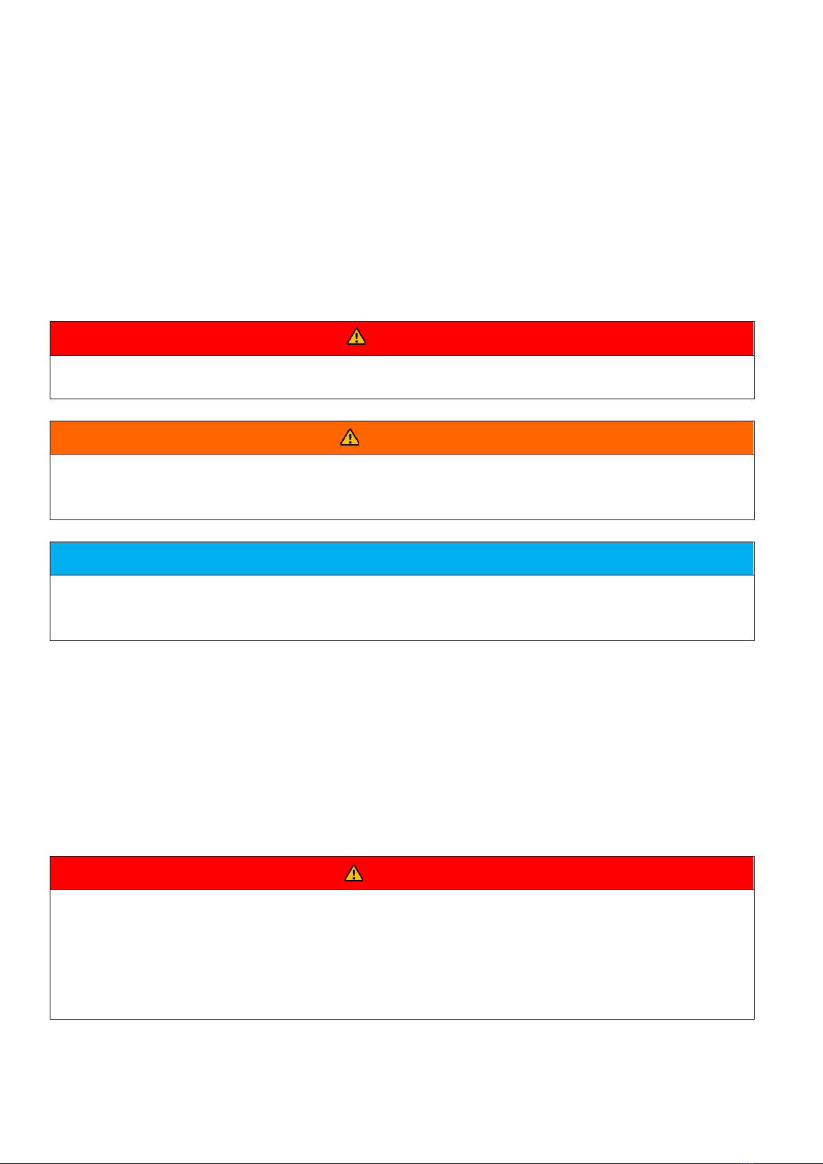
DANGER
DANGER indicates a hazardous situation which, if not avoided,will result in serious injury and/or fire.
WARNING
WARNING indicates a hazardous situation which, if not avoided,will result in property loss and/or void the
warranty.
NOTICE
NOTICE indicates normal situation which, if not avoided,will result in damage to the battery.
Follow local laws and regulations when installing, operating, or maintaining the equipment. The safety instructions in
this document are only supplements to local laws and regulations
1.2 Personal Safety
Personal Requirements
People who plan to install or maintain battery equipment must be trained, understand all necessary safety precautions,
and are able to correctly perform all operations.
Only qualified professionals or trained people are allowed to install, operate, and maintain the equipment.
DANGER
Do not place battery in an area accessible by children or pets.
Do not touch the energized battery,the temperature of the battery enclosure may increase during
operation.
Do not touch the energized battery terminals.
Do not stand on, lean on or sit on the battery.

UM0042_Ai-HB 2.56LG_EN_V01_0223 5
1.3 Personal Safety
Symbols on Battery
The electrical symbols on the battery relate to electrical safety. Please make sure you have fully understood them
before installation.
Symbol
Explanation
Electrical danger
Voltage exits when the battery is powered on. Only
qualified personnel are allowed to
operate.
Earth connector
Earth connection.
DC positive and negative
connectors
To identify positive and negative connectors of
DC power sources.
CE mark
The product meets CE certification.
WEEEtag
Batteries must not be disposed with general waste. It
must be appropriately recycled in accordance with local
regulations.
Recycle
Batteries can be recycled, please refer to your local
regulations regarding the correct disposal methods.
Electrical Safety
DANGER
Before installation, ensure that the equipment is complete and intact, otherwise electric shocks or fire may
occur.
Do not connect or disconnect power cables when battery is powered on .
Ensure the cables are terminated with the correct polarity. Failure to do so may result in electric arcs and
cause may cause fire and/or personal injury.
Do not connect the batteries in series or with batteries from different manufacturer´s.
Do not connect the battery directly to an AC power source.
Do connect the battery directly to the PV modules or PV array.
Do not connect batteries in parallel.
Do not connect the battery to a faulty and/or a non Solplanet inverter.
Do not create short circuits across the positive and negative terminals.
Ensure the grid is cut off and the battery is powered off before maintenance.
Ensure the earth cable is securely connected before operation.
Table of contents
Other Solplanet Camera Accessories manuals

Popular Camera Accessories manuals by other brands


Trojan
Trojan GC2 48V quick start guide

Calumet
Calumet 7100 Series CK7114 operating instructions

Ropox
Ropox 4Single Series User manual and installation instructions

Cambo
Cambo Wide DS Digital Series Main operating instructions

Samsung
Samsung SHG-120 Specification sheet

Ryobi
Ryobi BPL-1820 Owner's operating manual