Solplanet Ai-HB G2 Series User manual
Ai-HB G2 Series Battery
User Manual
Ai-HB 075A/Ai-HB 100A
Ai-HB 125A/Ai-HB 150A
Ai-HB 175A/Ai-HB 200A

Contents
1 General information....................................................................
1.1 About this document................................................................................
1.2 Product Validity........................................................................................
1.3 Target group.............................................................................................
1.4 Symbols....................................................................................................
2 Safety........................................................................................
2.1 Intended use............................................................................................
2.2 Important safety instructions..................................................................
2.3 Symbols on the label................................................................................
3 Unpacking and storage.............................................................
3.1 Scope of delivery.....................................................................................
3.2 Product storage.......................................................................................
4 Battery System overview..........................................................
4.1 Product description.................................................................................
4.2 Dimensions..............................................................................................
4.3 LED indicator...........................................................................................
4.4 Interfaces and functions.........................................................................
5 Mounting...................................................................................
5.1 Requirements for mounting.....................................................................
5.1.1 Requirements for Installation Location...........................................
5.1.2 Tools...............................................................................................
5.1.3 Safety Gear.....................................................................................
5.1.4 Additionally Required Installation Material....................................
5.2 Mounting ...............................................................................................
1
1
1
1
2
3
3
3
6
7
7
8
9
9
10
10
12
13
13
13
15
16
16
16

6 Electrical connection.................................................................
6.1 Overview of the connection area..............................................................
6.2 Connecting the Grounding Conductor....................................................
6.3 Connecting the power cable and network cable.....................................
6.4 Connection Diagram................................................................................
7 Commissioning...........................................................................
7.1 Inspection before commissioning.............................................................
7.2 Commissioning procedure........................................................................
8 Decommissioning the product...................................................
9 Technical data............................................................................
10 Troubleshooting .......................................................................
11 Maintenance..............................................................................
11.1 Cleaning the battery.................................................................................
12 Recycling and disposal..............................................................
13 EU declaration of conformity....................................................
14 Service and warranty................................................................
15 Contact.....................................................................................
22
22
22
24
27
28
28
28
30
32
34
36
36
37
37
38
39

General information1
This document describes the mounting, installation, commissioning, configuration, operation,
troubleshooting and decommissioning of the Ai-HB pre-assembled battery system (BS).
You will find the latest version of this document and further information on the BS in PDF format
at www.solplanet.net.
It is recommended that this document be readily accessible at all times.
1.1 About this document
This document is valid for the following models:
•Ai-HB 075A
•Ai-HB 100A
•Ai-HB 125A
•Ai-HB 150A
•Ai-HB 175A
•Ai-HB 200A
1.2 Product Validity
This document is intended for qualified persons who must perform the tasks exactly as described
in this user manual.
All installation work must be performed by appropriately trained and qualified persons.
Qualified persons must possess the following skills:
• Knowledge of how batteries work and are operated.
• Knowledge of how an inverter works and is operated.
• Training in how to deal with the dangers and risks associated with installing, repairing and
using electrical devices and batteries and installations.
• Training in the installation and commissioning of electrical devices.
1.3 Target group
UM0037_Ai-HB 075-200A_EN_V01_0523
1

1.4 Symbols
Information that is important for a specific topic or goal, however not related to
safety.
• Knowledge of all applicable laws, standards and directives.
• Knowledge of and compliance with this document and all safety information.
Not adhering to the prescribed instructions may potentially void the manufacturer's warranty. If
in doubt please contact the local Solplanet service team.
!
Indicates a hazardous situation which, if not avoided, will result in death or
serious injury.
DANGER
!
Indicates a hazardous situation which, if not avoided, could result in death or
serious injury.
WARNING
!
Indicates a hazardous situation which, if not avoided, could result in minor or
moderate injury.
CAUTION
Indicates a situation which, if not avoided, can result in property damage.
NOTICE
UM0037_Ai-HB 075-200A_EN_V01_0523
2

Safety 2
2.1 Intended use
The Ai-HB is a BS is for both residential and commercial applications and operates with Solplanet
hybrid inverters.
• It is a high voltage Li-ion BS controlled via a battery control unit (BCU).
• It can be operated in on-grid, off-grid and backup modes with all officially compatible
Solplanet inverters.
• The product is suitable for indoor and outdoor use.
• The product must only be used as stationary equipment.
• Alterations to the product are not allowed unless authorised in writing by Solplanet.
• Unauthorised alterations will void the guarantee and warranty claims. Solplanet will not be
held liable for any damage caused by such unauthorised alterations.
• The product is not suitable for supplying power to life-sustaining medical devices.
• Please ensure that no personal injury would lead due to the power outage of the battery
system.
• The product must only be used in countries for which it is approved for by Solplanet.
• Use this product only in accordance with the information provided in this documentation
and with the locally applicable standards and directives. Any other application may cause
personal injury or property damage.
• The type label must remain permanently attached to the product.
• This document does not replace any regional, state, provincial, federal or national laws,
regulations or standards that apply to the installation, electrical safety and use of the
product.
The product has been designed and tested in accordance with international safety requirements.
To prevent personal injury and property damage and to ensure long-term operation of the prod-
2.2 Important safety instructions
UM0037_Ai-HB 075-200A_EN_V01_0523
3
uct, read this section carefully and observe all safety information at all times.
DANGER
Danger to life due to high voltages of the battery!
When the battery system connected to the inverter, and the circuit breaker is ON, the
batteries will generate a high DC voltage which will be present in the DC cable and live
components.
• Do not touch non-insulated parts or cables.
• Do not touch the DC conductors.
• Do not touch any live components of the product.
• Do not open the product.
• All work on the product must only be carried out by qualified personnel who have read and fully
understood all safety information contained in this document.
• Disconnect the product from voltage sources and ensure it cannot be reconnected before working
on the product.
• Wear suitable personal protective equipment, in accordance with local regulations, when working
on the product.
DANGER
Danger to life due to electric shock where surge protection is
not used!
If there is no surge protection, a voltage surge can be conducted into the building and to
other connected devices in the same system through power cables, network cables or other
types of cable. Touching live parts and cables may result in death or lethal injury due to
electric shock.
• Ensure all devices in the same system and the inverter are integrated within an existing surge
protection systems/devices.
•Refer to local installation regulations to determine the requirements for the installation of surge
protection devices.
UM0037_Ai-HB 075-200A_EN_V01_0523
4

Damage to the battery system due to electrostatic discharge!
Internal components of the battery system can be irreparably damaged by electrostatic
discharge.
• Ground yourself before touching any component.
WARNING
Danger to life due to electric shock from destruction of mea-
surement devices due to overvoltage!
Overvoltage can damage a measurement device and result in voltage being present in the
enclosure of the measurement device. Touching the live enclosure of the measuring device
results in death or lethal injuries due to electric shock.
• Only use measuring devices with a higher voltage range than the system battery voltage.
NOTICE
Damage to the BCU due to particles and water!
Particles such as dust and sand can damage the BCU and impair its functionality.
• Only open the BCU cover when the humidity is within the permitted range of the product and the
environment is free of dust and sand.
NOTICE
WARNING
Risk of injury due to weight of product!
Injuries may result if the product is lifted incorrectly or dropped while being transported or
mounted.
• Lift and transport the product carefully.
• Wear suitable personal protective equipment, in accordance with local regulations, when working
on the product.
UM0037_Ai-HB 075-200A_EN_V01_0523
5
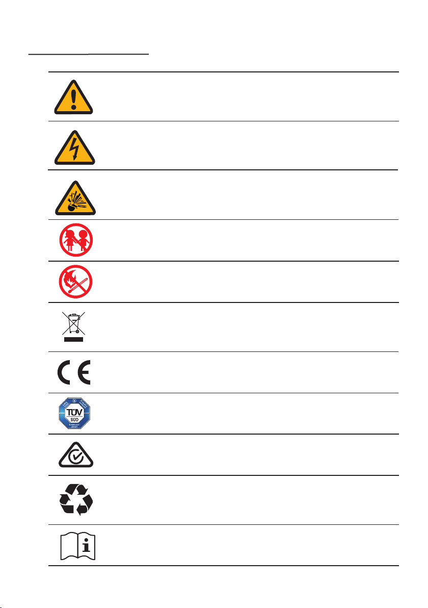
2.3 Symbols on the label
Beware of a danger zone
This symbol indicates that the product must be additionally grounded if additional
grounding or equipotential bonding is required at the installation site.
Beware of high voltage and operating current!
The product operates at a high voltage and current. Work on the product must only
be carried out by skilled and authorized personnel.
Beware of explosion!
The battery is an electro-chemical device, and there is an explosion risk in extreme
cases. Please keep away of it when the danger occurs.
Beware of danger to children!
The battery must be inaccessable to children.
Flammable
Keep the battery system away from open flames or ignition sources.
CE marking
The product complies with the requirements of the applicable EU directives.
Certification mark
The product has been tested by TÜV and obtained the quality certification mark.
CE marking
The product complies with the requirements of the applicable EU directives.
The battery is recyclable
The battery can be recycled by a professional recycling organization, please refer to
the relevant local regulations.
WEEE Designation
Do not dispose of the product together with household waste. Dispose the product
in accordance with local disposal regulations for electronic waste.
Observe the documentation
Read and understand all documentation supplied with the product.
UM0037_Ai-HB 075-200A_EN_V01_0523
6

Unpacking and storage3
3.1 Scope of delivery
Check the scope of delivery for completeness and any visible e. ternal damage. Contact your
supplier if the package is damaged upon delivery or is incomplete.
BCU and Base 1 BCU 1 Base 1 525 eagon
socket head screw 2
Documents 1
ositive cable and
negative cable 1
L-bracket 2
Cable gland 1
512 eagon
socket head screw 2 Terminating resistor 1
Battery odule 1 525 eagon
socket head screw 2
616
eagon screw 1
80 Epansion
Anchor Bolt 2
Battery odule ackage:
BCU and Base ackage:
UM0037_Ai-HB 075-200A_EN_V01_0523
7

3.2 roduct storage
Suitable storage is reuired if the euipment is not installed immediately:
• Store the battery in the original packing case.
• The storage temperature must be between -20C to 5C, and the storage relative humidi-
ty must be between 5% and 5%, non-condensing.
• The storage SOC: 25%~50%. Re-charge the battery every 6 months, to ensure no over-dis-
charge of the battery occurs.
•The packing with the euipment shall not be tilted or inverted.
•lace the euipment in a cool place away from direct sunlight.
•eep the euipment away from ammable, eplosive, and corrosive materials.
•eep the euipment away from rain.
• The product must be fully inspected and tested by authorised personnel before it can be put
into operation, if it has been stored for three or more months.
Not allowed
Temperature Relative humidity Storage time Original SOC
35%~85%
6 months 25%SOC50%
Below -20
C
0~25
C
35%~85%
1 months 25%SOC50%-20~5
C
Not allowed Above 5
C
Damage to the system due to under voltage
• Charge the over-discharged system within seven days when the temperature is above 25C.
• Charge the over-discharged system within fteen days when the temperature is below 25C.
NOTICE
UM0037_Ai-HB 075-200A_EN_V01_0523
8
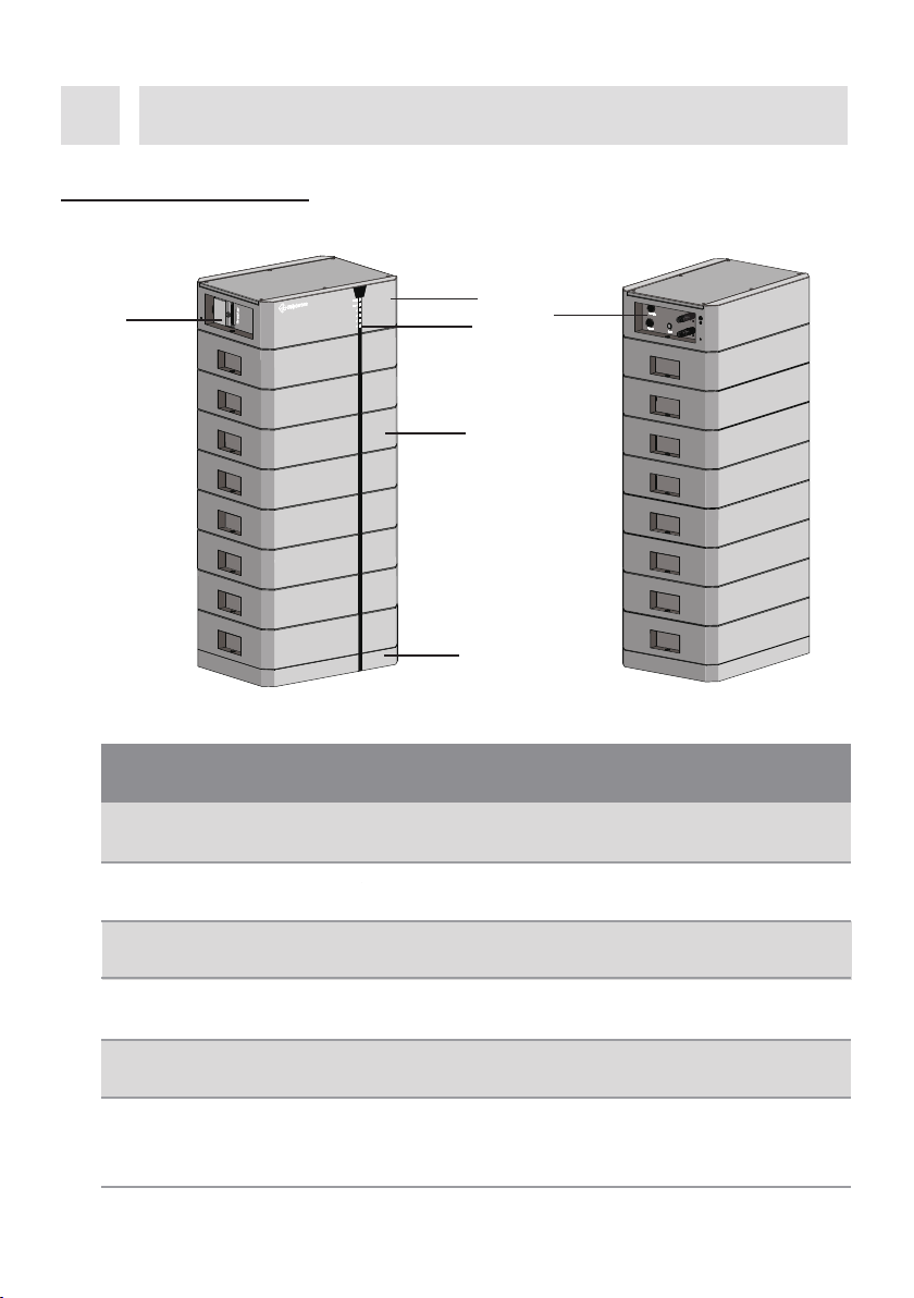
Battery system overview
.1 roduct description
1 BCU Battery control unit.
NO. Name Description
3Base The battery base which is used to support the battery.
Battery odule
Ai-B 2 battery module.
2
LED indicator Indicate the current operating state of the battery.
5Disconnect the high voltage from battery module to BCU.
6Interface anel
Circuit breaker
The interface panel containing the ONO button, DC
connectors and the Link ort In which is used to connect
the BCU to the connected battery module.
6
1
2
3
5
UM0037_Ai-HB 075-200A_EN_V01_0523
9

LED status denitions:
• Solid On: LED is permanently illuminated.
•O: LED is o (is not illuminated).
• Blinking: LED illuminates for 1 second and turns o for 1 second.
•ulsing: LED illuminates for 1.5 seconds and turns o for 5 seconds.
.2 Dimensions
.3 LED indicator
Unit:mm
The LEDs on the BCU indicates the status of the BS.
Indicates an alarm.
Status
Description
LED
unction
Solid ON BCU is power on, and the battery is waiting
to turn on.
Blinking
155
130
1250
55
50 30
UM0037_Ai-HB 075-200A_EN_V01_0523
10
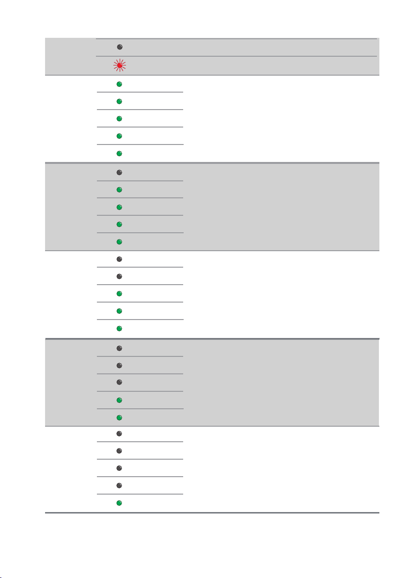
SOC:60%~80%
SOC:40%~60%
SOC
Normal state.
SOC:80%~100%
Solid ON Indicates a fault.
ON
ON
ON
ON
ON
OFF
ON
ON
ON
ON
OFF
OFF
OFF
ON
ON
OFF
OFF
ON
ON
ON
OFF
OFF
OFF
OFF
ON
OFF
SOC:20%~40%
SOC:0%~20%
SOC
SOC
SOC
SOC
UM0037_Ai-HB 075-200A_EN_V01_0523
11

There are five LEDs to indicate the State of Charge (SOC) of the battery and the
different status of the LEDs indicates the different working state of the battery.
• Solid ON indicate discharging state.
• Blinking On indicate Charging state.
• Pulsing ON indicate standby state.
4.4 Interfaces and functions
The product is equipped with the following interfaces and functions:
Communication (CAN) Interface - “Link Port”
The “Link Port” is an RJ45 port used for connecting the BCU to an inverter. The product can
communicate with the inverter through the CAN interfaces. The CAN interfaces can also be used
for the parallal operation of the products.
System startup
Turn on the circuit breaker. When the status indicator turns yellow, press the ON/OFF button for
at least 3s, all lights will turn on from bottom to top, BS is in working mode, and the device can be
charged and discharged normally.
System sleep
Press the ON/OFF button for at least 5s. Make sure that both the SOC indicator and the
status indicator of the BCU are off.
System shut down
Turn off the
circuit
breaker. Make sure that both the SOC indicator and the status indicator of
the BCU are off.
UM0037_Ai-HB 075-200A_EN_V01_0523
12
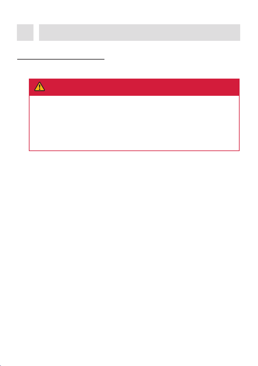
DANGER
!
Danger to life due to fire or explosion!
Despite careful construction, electrical devices can cause fires. This can result in death or
serious injury.
• Do not mount the product in areas containing highly flammable materials or gases.
• Do not mount the inverter in areas where there is a risk of explosion.
• A solid support surface must be available (e.g. concrete or masonry).
• The mounting location must be inaccessible to children.
• The installation location must be suitable for the weight and dimensions of the BS.
• Keep away from conductive (metal) dust.
• Keep away from water sources, heat sources and inflammable and explosive articles.
• The installation location must not be close to fire.
• The product should be mounted such that the LED indicators can be read without difficulty.
• The circuit breaker of the BS must always be freely accessible.
• The altitude of the installation location should be less than 3000 m.
• The operating temperature should be between -20°C ~ +50°C.
• The ambient humidity should be between 5-95%.
• The mounting location must not be exposed to direct solar irradiation. If the product is
exposed to direct solar irradiation, the exterior components may age prematurely and
overheating might occur. When becoming too hot, the BS reduces its power output to avoid
overheating, and will reduce its lifetime also.
Mounting5
5.1 Requirements for mounting
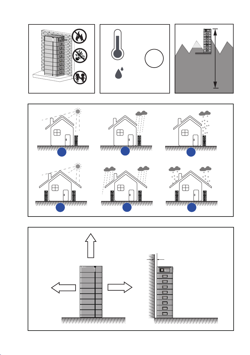
5.1.1 Requirements for Installation Location
UM0037_Ai-HB 075-200A_EN_V01_0523
13
-20C
50C
R.5%~5% ma. 3000 m
350 mm
600 mm
350 mm
×××
√√√
0~50 mm
I65
UM0037_Ai-HB 075-200A_EN_V01_0523
14
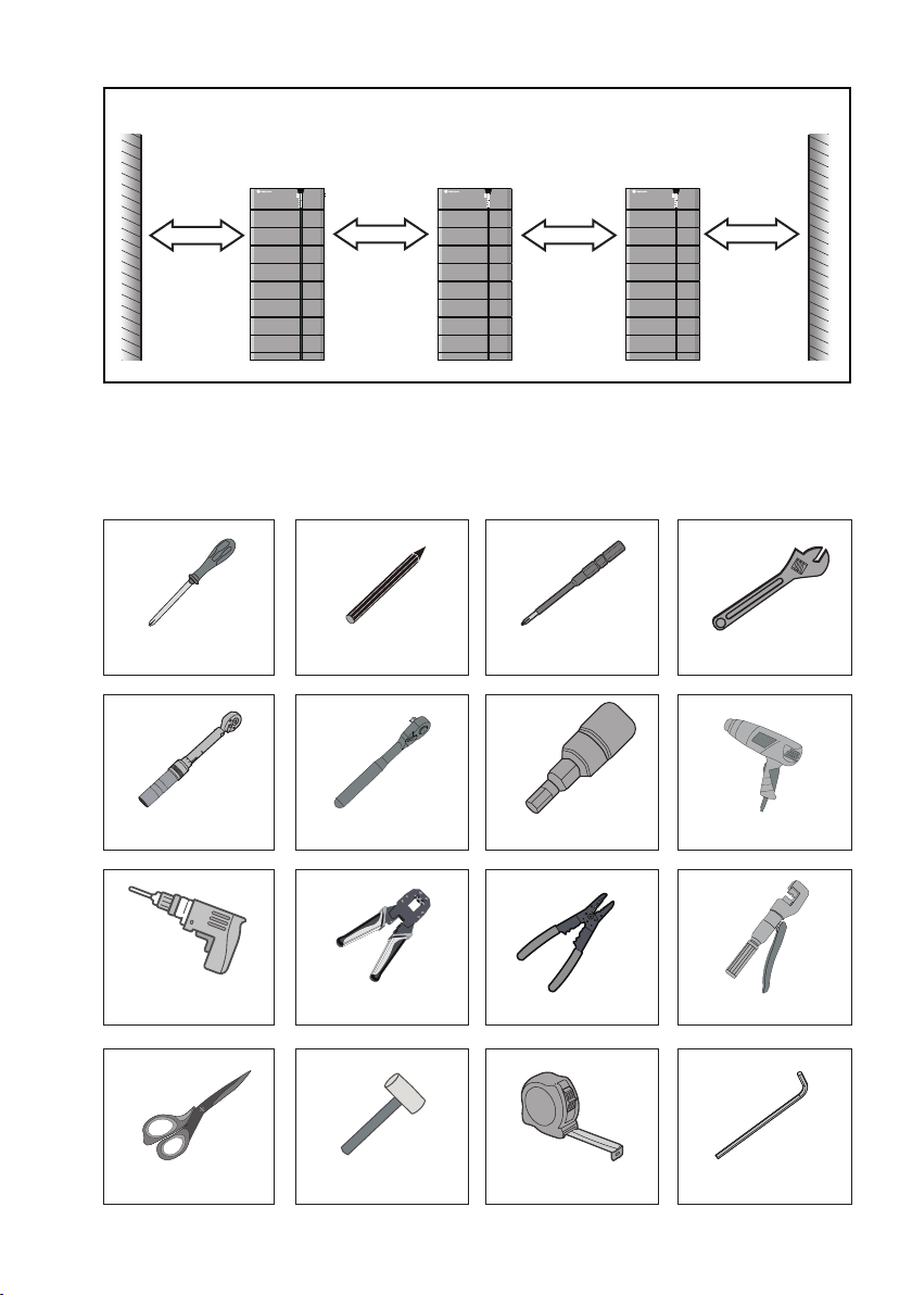
5.1.2 Tools
350 mm 350 mm 350 mm 350 mm
The tools in the following table may be needed during the installation.
hillips-screwdriver
Specication: arker pen hillips Screwdriver Bit Wrench
Torque wrench eagon socket bit S Heat Gun
Tape measure
Electric Drill Network Cable
Crimping Tool Wire Stripper Crimping liers
Scissor Hammer
Ratchet wrench
e ey S
UM0037_Ai-HB 075-200A_EN_V01_0523
15

DANGER
Danger to life due to high voltages of the battery!
When the battery system connected to the inverter, and the circuit breaker is ON, the
batteries will generate a high DC voltage which will be present in the DC cable and live
components.
• Do not touch non-insulated parts or cables.
• Do not touch the DC conductors.
• Do not touch any live components of the product.
• Do not open the product.
• All work on the product must only be carried out by qualified personnel who have read and fully
understood all safety information contained in this document.
• Disconnect the product from voltage sources and ensure it cannot be reconnected before working
on the product.
• Wear suitable personal protective equipment, in accordance with local regulations, when working
on the product.
5.2 Mounting
5.1.3 Safety gear
5.1.4 Additionally required installation material
Network Cable PE Terminal PE Cable Heat Shrink
Insulated gloves Safety goggles Safety shoes
Wear the following safety gear when working on the BS. Adhere to local occupational health and
safety standards.
UM0037_Ai-HB 075-200A_EN_V01_0523
16

Step 1:Remove the BCU and the base from the package and then separate the BCU and the
base by removing the two screws(525) that hold are holding them together.
M5
N.W: 15 kg
W ARNING
Risk of inury due to weight of product!
Inuries may result if the product is lifted incorrectly or dropped while being transported or
mounted.
• Lift and transport the product carefully.
• Wear suitable personal protective euipment, in accordance with local regulations, when working
on the product.
UM0037_Ai-HB 075-200A_EN_V01_0523
17
Other manuals for Ai-HB G2 Series
2
This manual suits for next models
6
Table of contents
Other Solplanet Camera Accessories manuals


