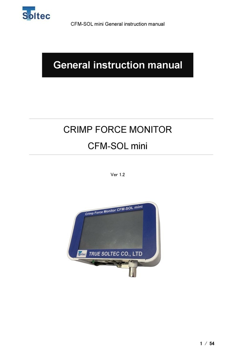
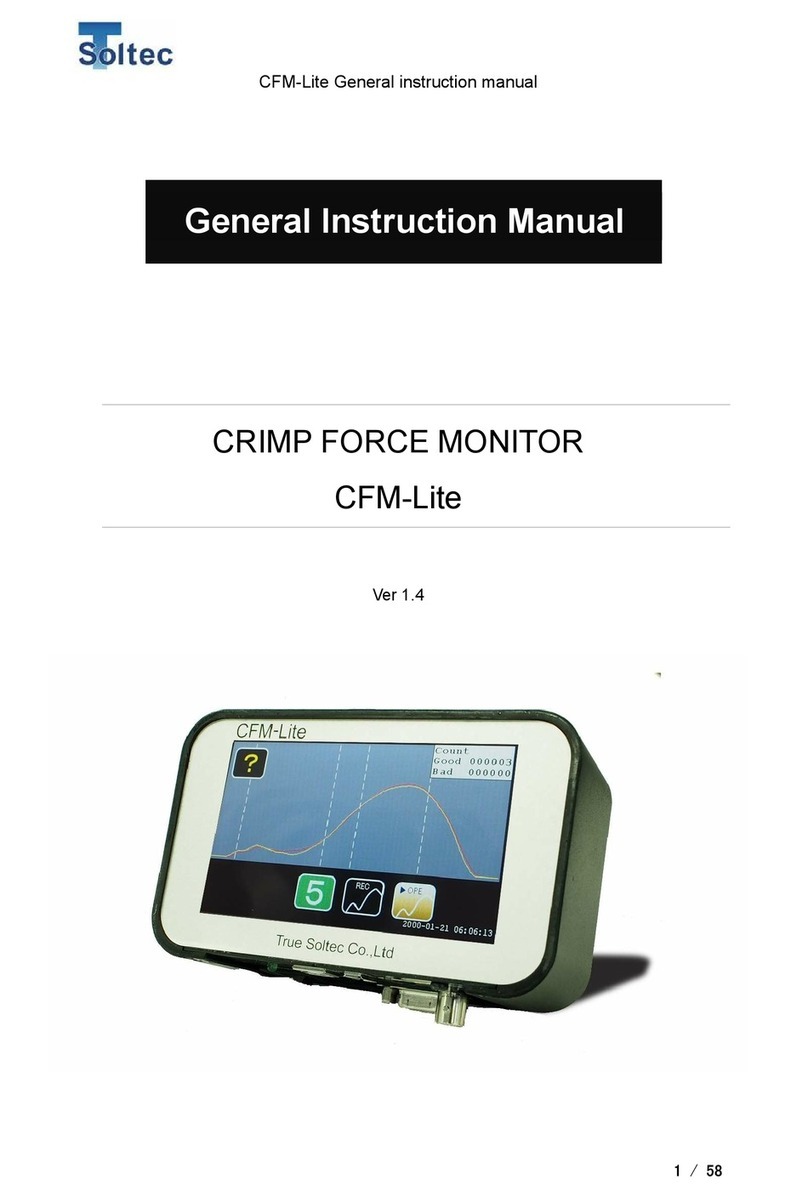
Soltec CFM-Lite User manual

CFM-Lite Installation Manual
1/ 64
Crimp Force Monitor
CFM-Lite
Ver 1.1
CFM-Lite Installation Manual

CFM-Lite Installation Manual
2/ 64
Update history
Version number
Date
Updated by
Detail
Version 1.0
2017.10.24
Masato Sato
Version 1.1
2018.12.14
Masato Sato
1.1 & 2.1
description for
dongle is updated.

CFM-Lite Installation Manual
3/ 64
CONTENTS
1. Overview ......................................................................................................................... 5
1.1. The main unit, standard accessories and optional accessories.............................. 5
1.2. Connection of accessories....................................................................................... 9
1.3. Main specifications of the unit.................................................................................. 9
1.4. Terms explanation.................................................................................................. 10
1.5. Input and Output.................................................................................................... 12
1.6. Signal interface...................................................................................................... 14
1.6.1. External trigger input ...................................................................................... 14
1.6.2. External RESET.............................................................................................. 15
1.6.3. External TEACH ............................................................................................. 15
1.6.4. STOP signal.................................................................................................... 16
1.6.5. EJECT............................................................................................................. 18
1.7. PC communication................................................................................................. 18
1.8. AC Power adaptor.................................................................................................. 18
1.9. BNC........................................................................................................................ 18
1.10. USB memory...................................................................................................... 18
1.11. Sensor................................................................................................................ 19
2. Installation..................................................................................................................... 21
2.1. First of all : opening the box................................................................................... 21
2.2. Packed parts.......................................................................................................... 22
2.3. PSS sensor installation.......................................................................................... 24
2.3.1. How to set on the machine : example............................................................ 24
2.3.2. Procedure of setup the sensor....................................................................... 25
2.4. Wiring of interlock signal (Stop signal) for the machine........................................ 31
2.5. Lay out of the cables of sensor and I/O................................................................. 39
2.6. How to set up mounting bracket for the main unit................................................. 42
2.7. How to install PC software..................................................................................... 48
2.8. Let’s get started...................................................................................................... 53
3. Other installation ........................................................................................................... 55
3.1. Proximity sensor installation.................................................................................. 55
3.2. Base plate and sensor preload.............................................................................. 57
3.3. Eject signal connection.......................................................................................... 58
3.4. How to set up the insulation plate for PSS sensor. ............................................... 59

CFM-Lite Installation Manual
5/ 64
1. Overview
This manual guides you the way how to install the system successfully.
1.1. The main unit, standard accessories and optional accessories
Front
Rear
All are operated via the touch panel in the front. Only the power switching button is
located at the bottom.
Bracket set
holes (M5)

CFM-Lite Installation Manual
6/ 64
Bottom
FG (Frame Ground) must be connected firmly to the earth via e.g. the earth terminal of
the table tap, crimping machine, the formal earth terminal prepared by the factory in
order to prevent the external noise.
Accessories
Packed together
Non packed together
CFM-Lite main unit
PC software (available by download from PC web
site)
Sensor : Standard is PSS type,
optionally available is FTW or
FTC model.
General instruction manual and Installation manual
(available by download from PC web site)
BNC cable for sensor
PC (user preparation)
I/O cable for control
USB-AB type cable (user preparation)
AC adaptor
USB memory (user preparation)
Dongle key (optional item)
Mounting bracket
Basic instruction manual (print)
Power switch
USB-B type port for
USB-AB cable
USB-A type
port for USB
memory
Dongle key port
AC adaptor
port
Sensor input
D-sub 9 pin port
for I/O cable
Power LED
FG
Serial No. seal

CFM-Lite Installation Manual
7/ 64
Photos of packed items:
BNC cable
1.5 m long BNC cable connects the
force sensor and CFM-Lite main unit.
I/O cable
1.5 m long Input and Output cable
with D-sub 9 pins connector for
connecting CFM-Lite and the machine
control
Dongle key (optional)
This key blocks selected operations
from unwanted hand of operators
PSS sensor
Force detection is made by measuring
the machine body’s elongation. See
sensor details at 1.11. Sensor
ACAdaptor
Noise proof type adaptor is prepared.
Caution: Do not use other low costAC
adaptors in the market.
Mounting bracket
Standard bracket for mounting the
main unit: 170mm long body can be
set by the triangle base plate (M5).

CFM-Lite Installation Manual
8/ 64
Photos of non-packed together
PC is to be normal type in the market.
USB cable is available in the market, too.
USB cable (AB type)
B connector
A connector

CFM-Lite Installation Manual
9/ 64
1.2. Connection of accessories
1.3. Main specifications of the unit
Outer dimensions
W 137mm x H 84mm x D 50mm
Analog sensor
signal
Resolution 12bit
Max sampling rate 20kHz
Sensor
FTW series (ring type force sensor, cable output, 0.1 to 10 ton)
PSS series (piezo strain sensor, high /middle / low sensitivity
models)
FTC series (ring type force sensor, connector output, 2 or 4 ton)
I/O cable
“Refer to 1.5. Input and Output”
USB
communication
1) PC communication (USB2.0)
2) USB data memory (max 64GB saved)
Power
Adapter Tec made, model ATM012T-W240U
(Input 100~240V AC、Output 24V DC・0.5A)
Other all AC adaptors are out of warranty if trouble should happen.
Operating
temperature
0~40 degrees C, Humidity 90% or lower but no dew
Circumstances
RoHS regulation is performed.
Dongle
key
BNC cable
PSS sensor
USB-AB cable
AC adapter
I/O cable

CFM-Lite Installation Manual
10 / 64
1.4. Terms explanation
Crimp Force Monitor = CFM : CFM monitors cable’s terminal crimping is
monitored by using a force sensor. Every crimped force data is compared with
the standard (= good ) force data (reference force curve) to judge if it is a good
crimping or defect.
Operation = OPE.: It is a mode of CFM-Lite. It controls data if it is good or bad.
Production is done under OPE mode.
TEACH: It is a mode of CFM-Lite. Before starting production, two good crimp
data will create the reference force curve by which next coming all data can be
judged. This mode teaches the standard; therefore we say it as “Teach”.
Tolerance : Data deviation from the standard is expressed by percentage %. The
acceptable limit of + tolerance value and –tolerance value will be setup for
controlling good and defect data.
Parameters : Only selected parameters can be accessed by touching the front
panel of the main unit.All the others can be precisely conditioned by selecting
parameters by PC software.
Trigger : This word is used in broad sense. We mean it as the start timing of
force signal getting. There are two ways of triggering; one is the automatic
trigger “Auto Trigger” CFM-Lite detects the right force level to start getting
automatically, and the other is the external switch trigger which is made by a
high response type sensor set on the crimping machine monitoring the machine
ram motion. Normally the automatic trigger can work. However bad machine
conditions and poor material quality will make force data very unstable. In such
cases, we should recommend you to use the external trigger. Consult with us or
our agent.
Stop signal : CFM-Lite outputs stop signal when it detects a defect crimp. It locks
the machine not to re-start production until the operator checks it and remove
the cause. The stop signal line is often connected in series to the foot switch
circuit of manual press.

CFM-Lite Installation Manual
11 / 64
Eject signal: For more advanced machines using automatic running system will
use this signal as the confirmation of good crimp completion. The machine will
receive this pulse signal to take the next cycle.

CFM-Lite Installation Manual
12 / 64
1.5. Input and Output
Input and Output circuit
1) +24Vout
2) TRIGGER
3) RESET
4) TEACH
5) STOP_NC
6) STOP_COM
7) STOP_NO
8) EJECT
9) GND
10) FG(Shell)
11) FG(Shell)
I/O
DSUB 9pin

CFM-Lite Installation Manual
13 / 64
I/O pin assignment
PIN No.
Description
Wire color
1
Power
24V(output)
Orange/Black 1
2
TRIGGER
External trigger input
Orange /Red 1
3
RESET
External reset input
Yellow/Black 1
4
TEACH
External teach input
Yellow/Red 1
5
STOP
Stop signal (N.O)
Green/Black 1
6
STOP
Stop signal (COM)
Green/Red 1
7
STOP
Stop signal (N.C)
Gray/Black 1
8
EJECT
Eject output
Gray/Red 1
9
GND
Ground
White/Black 1

CFM-Lite Installation Manual
14 / 64
1.6. Signal interface
See “1.5 Input and Output”
1.6.1. External trigger input
A high speed optical switch will make the pin 2 (TRIGGER) and pin 9 (FND) shorted
for triggering. But, if the automatic trigger mode is selected, this signal is ignored.
This trigger timing is expressed as HIGH to LOW change. The system demands
Low period longer than 10m seconds.
The measurement starts from (3) and ends at (4). Internally the system gets margin
area 10% each for left and right sides.
Triger level (1)
[Diagram] Signal exceeding the trigger level
Trig. Signal
(Switch ON)
Force
Force monitor start (2)
Force measurement (3)
Force monitor stop (4)
Triger level
(set by PC)

CFM-Lite Installation Manual
15 / 64
It monitors for 100msec. to confirm that force curve exceeds the trigger level.
If it cannot confirm such exceeding of the trigger level, the force curve with peak
of at (2) –(3) period is obtained.
1.6.2. External RESET
RESET signal release errors of data error, sensor error and TEACH error. It is the
external resetting, which will be sent from the press machine or external switching
box. To make it ON, pin 3 (RESET) and pin 9 (GND) should be short circuited.
When the system operates without error, this RESET signal is ignored. Caution:
make the low time (short-circuited) longer than 10msec. for sure.
1.6.3. External TEACH
TEACH signal starts teaching. It is the external TEACH signal from the machine.
Make pin 4 (TEACH) and pin 9(GND) short circuited to set ON. When the CFM is
already in TEACH mode, this signal is ignored. Caution: make the low time (short-
circuited) longer than 10m sec. for sure.
Triger Signal
[Diagram] Signal not exceeding the trigger level
Triger level
(set by PC)
Force
Force monitor start (2)
Force measurement (3)

CFM-Lite Installation Manual
16 / 64
1.6.4. STOP signal
STOP signal stops operation of machine. There are normally open (NO) signal and
normally close (NC).
NO:
When the main unit is turned on, it keeps the relay contact opened.
NC:
When the main unit is turned on, it keeps the relay contact closed.
The below is the relay contact circuit. It shows the normal mode. When it should
happen error, the mode is reversed, namely the NO contact is closed and NC
contact is opened.
Stop signal contact
5
STOP
(N.O)
GRN/BLK 1
6
STOP
(COM)
GRN/RED 1
7
STOP
(N.C)
GRY/BLK 1
Normally open NO
Normally close NC
Common COM

CFM-Lite Installation Manual
17 / 64
Contacts condition
Pin 5(STOP (N.O))
Pin 7(STOP (N.C))
Power OFF
Close
Open
TEACH
Open
Close
OPE
Open
Close
Tolerance setting
Close
Open
Parameter screen (PC)
Close
Open
Error happens
Close
Open
Ordinary manual type press control has no special connector for external stop
signal. Therefore, we recommend you to break the foot switch circuit for CFM stop
signal in serial so that the foot switch can be locked at the error detection. See “2.4
Interlocking signal (STOP) for press machine”.
Foot Switch
CFM-STOP
Machine

CFM-Lite Installation Manual
18 / 64
1.6.5. EJECT
EJECT signal is output to a semi-automatic machine which has the electrical control
functions to receive the eject-pulse signal as the confirmation of good crimp and start
the next press cycle. The eject pulse width is 100m sec. It is possible to select Eject
output at good crimping or bad crimping as a parameter. Normally Pin 8 (EJECT) and
9(GND) is open (= HIGH). When EJECT is output, it becomes LOW and maintain
100ms and returns to HIGH. See “3.3 Eject signal connection”.
1.7. PC communication
See [1.3 main unit specifications]
1.8. AC Power adaptor
See [1.3 main unit specifications]
1.9. BNC
BNC cable is used for the sensor connection. Use only ours.
1.10. USB memory
Force curve is kept in the USB memory. When it is inserted to the USB port, data is
automatically stored in time order.
Machine is
crimping
Eject output
100mSec pulse
Force curve
Pulse width = 100ms
Eject is output within 100ms when the unit is set as short measurement
mode (measurement max. 100ms).
Eject is output within 500ms when the unit is set as long measurement
mode (measurement max. 500ms)
Lower dead point

CFM-Lite Installation Manual
19 / 64
1.11. Sensor
Piezoelectric strain sensor, PSS50
PSS50 is provided as standard accessory. It can be screwed to machine body easily.
Refer to “2.3 PSS sensor installation”for details. It’s sensitivity is 90mV/μST. The
μST is called as micro-strain, a physical term expressing how micron meter
elongated per 1 meter long base material. This sensor outputs high voltage in
proportion to applied elongation. Namely, when the machine body strains at
crimping, PSS sensor output proportional voltage to its elongation.
Other PSS series sensors: PSS100, PSS25
PSS100 is of 160mV/μstrain for highly rigid type press machines.
PSS 25 is of 40mV/μstrain for low rigid machines.
* For selection of right PSS model, please consult with us. They are all same size.
Only the sensitivity is classified.
Sensitivity 90mV/μstrain(PSS-50)
Rated strain limit 50μstrain (physical overload is 400μstrain)
Low cut frequency About 0.1Hz
Linearity 3FS %
Output impedance 100Ωor lower
Base noise 500μVrms or lower
Carrier base voltage 11V±1V
Recommended set torque 7~10N-m
Max. allowable torque 10N-m
Net weight About 73g
Power Voltage 24~27V, constant current2~10mA
Operating principle Sharing, piezoelectric effect
Sensor casing Stainless steel
Connector Miniature type, No.10-32UNF
Set screw M6 type set screw, flat head、φ6.4mm
Operating temperature range -20~60 degreeC

CFM-Lite Installation Manual
20 / 64
Other sensors are also available.
When your press has no space to put PSS sensor or you prefer to receipt of the
force directly –not via machine’s distortion, you can choose our ring type
piezoelectric force sensors.
FTW series are cable output type, ranging from 100kg, 500kg, 1ton, 2ton, 2.5
ton, 5ton and 10ton.
FTC series are connector output type, ranging 2ton and 4 ton.
In order to receive the crimping force, the sensor must be set in the applicator’s base
plate or the machine ram. Usually we recommend to put the FTW sensors in the
base plate, which will be designed and fabricated by us. You will consult with us or
our agent for sensor selection, location of sensor, jig design and installation. It must
be done before issuing your purchase order.
As for the base plate type installation of FTW sensors, refer to “3.2 base plate and
sensor preloading”.
Sensor model
(max load)
FTW05(500kg)
FTW20(2t)
FTW255(2.5t)
FTW50(5t)
FTW100(10t)
[FTW]
They are
sandwiched in
the base
plates
110t
Ex.FTW20 cable output
FTC208(2t)
FTC408(4t)
[FTC]
They are
pinched in the
ram adaptor.
Sensor cable
must be routed
carefully not
for breakage
Ex.FTC208 connector output
[Connection]
Sensor Pre-amp. BNC cable
4 ± 0 . 0 0 5
φ 1 8 . 9
φ 6 . 4 1 3 . 9
3 0 1 8 . 1
φ 2 . 3 L = 2 0 0
10t
7 . 8 7 ± 0 . 0 2 5
0 . 2
0 . 1 5
φ 1 6 . 5 1
φ 6 . 3 8
1 9 . 5
φ 7
Connection
cable
Other manuals for CFM-Lite
1
Table of contents
Other Soltec Monitor manuals
Popular Monitor manuals by other brands

Fujitsu
Fujitsu SCALEOVIEW C17-7 user manual
Dell
Dell 2407WFP - UltraSharp - 24" LCD Monitor user manual
Dell
Dell E157FPT Environmental Data Sheet

Fujitsu
Fujitsu Plasmavision PDS4208W-B user manual
Advan
Advan AMM15TK3 Operation manual

Samsung
Samsung 400FP-2 - SyncMaster - 40" LCD Flat Panel... user manual

