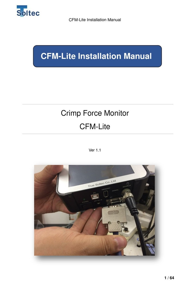
Soltec CFM-Lite Instruction manual

CFM-Lite General instruction manual
1 / 58
CRIMP FORCE MONITOR
CFM-Lite
Ver 1.4
General
I
nstruction
M
anual

CFM-Lite General instruction manual
2 / 58
UPDATED HISTORY
Version Date Updated by Details
Version 1.0 2017.10.24 Masato Sato
Version 1.1 2017.11.13 Masato Sato 1. Overview is updated
Version 1.2 2018.12.14 Masato Sato 1.2 description for dongle is
updated
Version 1.3 2020.01.22 Suzuki Tomomi Update functions of CFM-Lite
(FW V1.17, SW V1.0.4.5)
Version1.4 2023.4.26 Tatsuya
Yanagawa
Update functions of CFM-Lite
(FW V1.35, SW V1.0.6.2)

CFM-Lite General instruction manual
3 / 58
INDEX
1. Overview ................................................................................................................................................................. 5
1.1. Introduction ............................................................................................................................................ 5
1.2. Main Unit and Accessories ............................................................................................................ 5
1.3. CFM-Lite Specifications .................................................................................................................. 7
1.4. I/O pin assignment ............................................................................................................................. 7
1.5. Detectable Defects ............................................................................................................................ 8
1.6. Wire size................................................................................................................................................ 12
2. Tolerance .............................................................................................................................................................. 13
3. CFM-Lite Operation ......................................................................................................................................... 14
3.1. Main Unit ............................................................................................................................................... 14
3.1.1. Start up .............................................................................................................................................. 14
3.1.2. TEACH .............................................................................................................................................. 14
3.1.3. OPE (Operation) .......................................................................................................................... 17
3.1.4. Auto Trigger Check ..................................................................................................................... 18
3.1.5. Error screen .................................................................................................................................... 18
3.1.6. Sensor Error ................................................................................................................................... 19
3.1.7. Tolerance Setting ......................................................................................................................... 20
3.1.8. Parameter Screen ....................................................................................................................... 21
3.1.9. Reset Counting ............................................................................................................................. 21
3.1.10. Initialize Parameter ..................................................................................................................... 22
3.1.11. Other Icons ...................................................................................................................................... 22
3.1.12. Other Functions ............................................................................................................................ 23
3.2. PC software(Pro-Lite) .............................................................................................................. 23
3.2.1. Pro-Lite Start up ........................................................................................................................... 23
3.2.2. Example of Force Curve Display ......................................................................................... 24
3.2.3. Tolerance Setting ......................................................................................................................... 25
3.2.4. Parameter Settings (Logged on).......................................................................................... 25
3.2.5. Parameter Settings (Logged off) .......................................................................................... 30
3.2.6. Configuration Settings ............................................................................................................... 31
3.2.7. Utility Settings ................................................................................................................................ 32
3.2.8. Display Force Curve Data ....................................................................................................... 33
3.2.9. Area Modification ......................................................................................................................... 34

CFM-Lite General instruction manual
4 / 58
3.2.10. Brightness Adjustment .............................................................................................................. 35
3.2.11. Preload Setting ............................................................................................................................. 35
3.2.12. Auto Trigger Check ..................................................................................................................... 36
3.2.13. Capture raw force data ............................................................................................................. 37
3.2.14. Head Room ..................................................................................................................................... 39
3.2.15. Communication Error ................................................................................................................. 44
4. Technical Description ...................................................................................................................................... 45
4.1. Good / Bad Judgement (T1/T2/T3/TD) ................................................................................. 45
4.2. Maintenance for Applicator and Crimping tools. ............................................................... 48
5. Troubleshooting .................................................................................................................................................. 50
5.1. Major defects which must be detected are not detected ............................................. 50
5.2. Small defects are not detected .................................................................................................. 51
5.3. Defect of large wire is not detected ......................................................................................... 52
5.4. Detecting defect of equal to or smaller wire than AWG30 is unstable .................. 52
5.5. False alarms occur frequently, which affects the production process................... 53
5.6. No force curve is captured when the terminal is crimped ............................................ 55
5.7. The power of the main unit does not turn ON when the power switch is ON. .. 56
5.8. Communication with PC cannot be established. .............................................................. 56
5.9. Electrical noise enters and the force curve shows strange behavior. ................... 56
5.10. No terminal crimp is detected after crimping ...................................................................... 56
6. Index ....................................................................................................................................................................... 57
7. Warranty ................................................................................................................................................................ 58

CFM-Lite General instruction manual
5 / 58
1. Overview
1.1. Introduction
Crimp Force Monitor CFM-Lite is integrated into manual crimping machine or semi-
automatic crimping machine, to check the crimp quality through monitoring crimping force.
All operations are performed via the LCD touch panel on the main unit. Standard
settings and operations are simplified with only crimping force curve display and some
buttons on the main screen, so that customers can handle it easily.
For further parameter settings, it is possible to set up from the PC software.
1.2. Main Unit and Accessories
Front
Rear
Operations are performed via the LCD touch panel. Only the power switch locates at
the bottom of the main unit.
Bracket Mounting
Screw Holes (M5)

CFM-Lite General instruction manual
6 / 58
Bottom
FG (Frame Ground) must be connected firmly to the earth via e.g. the earth terminal of
the table tap, crimping machine, the formal earth terminal prepared by the factory in order
to prevent the external noise.
Accessories
Packed together Non packed together
CFM-Lite Main Unit PC software (Download from True Soltec website)
Sensor:
・Standard: PSS type
・Others: FTW or FTC model.
General instruction manual and Installation manual
(Download from True Soltec website)
BNC cable for sensor PC (prepared by users)
I/O cable for control USB-AB type cable (prepared by users)
AC adaptor USB memory (prepared by users)
Dongle key (optional item)
Mounting bracket
Basic instruction manual (print)
Power switch
USB
-
B type port for
USB-AB cable
USB-A type
port for USB
memory
Dongle key port
AC adaptor
port
Sensor input
D
-
sub 9 pin port
for I/O cable
Power LED
FG
Serial No. seal

CFM-Lite General instruction manual
7 / 58
1.3. CFM-Lite Specifications
Outer dimensions W 137mm x H 84mm x D 50mm
Analog sensor
signal
Resolution 12bit
Max sampling rate 20kHz
Sensor FTW series (ring type force sensor, cable output, 0.1 to 10 ton)
PSS series (piezo strain sensor, high /middle / low sensitivity
models)
FTC series (ring type force sensor, connector output, 2 or 4 ton)
I/O cable Refer to “1.4. I/O pin assignment”
USB
communication
1) PC communication (USB2.0)
2) USB data memory (max 64GB saved)
Power Adapter Tec made, model ATM012T-W240U
(Input 100~240V AC、Output 24V DC・0.5A)
Other all AC adaptors are out of warranty if trouble should
happen.
Operating
temperature
0~40 degrees C, Humidity 90% or lower but no dew
Circumstances RoHS regulation is performed.
1.4. I/O pin assignment
The above is the relay output of I/O pin assignment when the main unit is powered off.
PIN No.
Description Wire color
1 Power 24V(output) Orange/Black 1
2 TRIGGER External trigger input Orange /Red 1
3 RESET External reset input Yellow/Black 1
4 TEACH External teach input Yellow/Red 1
5 STOP Stop signal (N.O) Green/Black 1
6 STOP Stop signal (COM) Green/Red 1
7 STOP Stop signal (N.C) Gray/Black 1
8 EJECT Eject output Gray/Red 1
9 GND Ground White/Black 1

CFM-Lite General instruction manual
8 / 58
1.5. Detectable Defects
This section describes all the defects that CFM-Lite can and cannot effectively
detect, given the condition that crimping machines, applicators, and tools are in
good performance.
Defects that can be detected nearly 100% (major defects)
- No wire inside the crimp
- No strip crimp
- Double terminal crimp
Defects that can be detected depending on the working conditions
- Crimp height change +/-0.03mm
- 1 of 7 wire strands being cut or out: depending on the number of wires and
wire size.
- High insulation and low insulation (high feed and low feed)
Fitting part Wire barrel
W
ire
Insulation
Insulation barrel
Crimped terminal

CFM-Lite General instruction manual
9 / 58
A) Defects that can be detected nearly 100% (major defects)
a) High feed (Wire barrel pinches the insulation)
This is the case where the wire barrel pinches the insulation (deep-feed defect).
The total force applied onto the wire barrel increases, which generates a change on
the crimping force curve. That’s why CFM can detect it.
b) Low feed (Total volume of wire inside the wire barrel decreases)
This is the case where the wire top position is pulled down and stays inside the wire
barrel (low-feed defect). The total volume of wire inside the wire barrel decreases,
which generates a change on crimping force curve. Therefore, CFM can detect it.
Fitting part Wire barrel
Wire
Insulation
Insulation barrel
Example of high feed (detectable)
Fitting part Wire barrel
Wire
Insulation
Insulation barrel
Example of low feed (detectable)
Wire top position

CFM-Lite General instruction manual
10 / 58
B) Defects that are difficult to detect
a) High feed (Wire barrel does not pinch the insulation)
This is the case where the wire barrel does not pinch the insulation (deep-feed
defect). The total force applied onto the wire barrel does not change, which means
the crimping force curve does not change either. That’s why it is difficult to detect.
b) High feed (The insulation is under the bell mouth, but not pinched by the wire
barrel)
This is the case of deeper feed than usual. The insulation looks like being under the
bell mouth. It seems easy to detect this kind of deep feed but the insulation is not
pinched into the wire barrel. In this case, the total force applied onto the wire barrel
does not change. Neither do the crimping force curve. That’s why it is difficult to
detect.
c) Low feed (The total volume of wire inside the wire barrel does not decrease)
This is the case of lower feed than usual. The wire top does not appear between the
wire barrel and the fitting part window. It seems easy to detect this type of low feed.
However, as shown in the above picture, if the total volume of wire inside the wire
barrel stays the same, so does the total crimping force. That means the curve also
does not change, which is very hard to detect.
Fitting part Wire barrel
Wire
Insulation
Insulation barrel
Example of deep feed (hard-to-detect case)
Fitting part Wire barrel
Wire
Insulation
Insulation barrel
Example of deep feed (hard-to-detect)
Fitting part Wire barrel
Wire
Insulation
Insulation barrel
Example of low feed (hard-to-

CFM-Lite General instruction manual
11 / 58
d) Deformation of the insulation barrel
Unlike to the wire barrel, the crimping force applied to the insulation barrel is quite
small. Therefore, even if the insulation barrel is deformed, the curve does not
change significantly.
e) Wire strands are protruded outside the barrel and laid on the terminal
This is a defect where the strands go out of the wire barrel and is crimped on the
outside of the barrel. The force curve does not change, because the total amount of
pressure on the wire barrel does not change that much.
f) Fitting part defect
This is the defect of the fitting part. It does not make change to the force curve.
Below are the examples of good/bad crimping force curve with AWG20, 7 strands
wire.
Good
This is a normal crimping
force curve of a good crimp.
The reference force curve
(red) and the actual force
curve (yellow) are the same in
shape and size.
Strand out 1 pc.
The actual force curve is
lower at all area, T1/T2/T3.
Crimped terminal sample (wire
strand out 1pc.)

CFM-Lite General instruction manual
12 / 58
1.6. Wire size
The smallest wire size that CFM-Lite can inspect, is AWG28.
Strand out 2 pcs.
Deep feed
The actual force curve is lower
at all area, T1/T2/T3.
Due to an early touch to the
insulation (not to the wire), the
beginning of the force curve
goes high at T1. Peak is smaller
and earlier due to insufficient
force on the wire.
Low feed
This curve is of either strand
being cut / out, or low feed. The
force curve is lower at all areas
T1, T2, T3.
Crimped terminal sample (wire
strands out 2pc.)
Crimped terminal sample
(High feed)
Crimped terminal sample
(Low feed)

CFM-Lite General instruction manual
13 / 58
2. Tolerance
CFM-Lite has 5 tolerance levels. No. 1 is the smallest, while No. 5 is the biggest. In each
judgement area, if the result value (%) exceeds the +/- limit, CFM-Lite judges this is error.
Tolerance index (initial setting)
T1+ T1- T2+ T2- T3+ T3- TD
1 25.0 99.9 10.0 5.0 4.0 2.0 25.0
2 30.0 99.9 14.0 7.0 6.0 3.0 30.0
3 35.0 99.9 18.0 9.0 8.0 4.0 30.0
4 40.0 99.9 22.0 11.0 10.0 5.0 40.0
5 OFF OFF OFF OFF 20.0 20.0 OFF
In index No. 5, T1, T2, and TD are initially OFF, only T3 is used for judgement.
Specifically, CFM monitors only the peak of force curve at the lower dead point to detect
major defects. These % can be changed from the PC software, by directly changing the
numbers in the text box. See “3.2.4. Parameter screen (Logging in)”. If it is left in blank, it
is set as OFF.
Description of each tolerance number:
1. Smallest tolerance. Recommended if you would like to detect 1 of 7 strands out or
break. However, this would increase the number of false alarms (CFM says NG for
good crimp).
2. Stricter than the standard. Small defects can be detected.
3. Standard tolerance. This tolerance is set by default. Small defects can be detected,
while there are less force alarms. Its target is to detect 2 of 7 strands break or out.
4. Bigger (easier) than the standard. Major defects can be detected, while less force
alarm.
5. Biggest tolerance. T1, T2, and TD are OFF, and not used for judgement. Only T3 is
used for judgement to monitor the peak force at the lower dead point of the machine.
The major defects can be detected and there are least false alarms.

CFM-Lite General instruction manual
14 / 58
3. CFM-Lite Operation
3.1. Main Unit
3.1.1. Start up
It is shown when the turning on the main unit.
It automatically goes to TEACH screen after 3 seconds.
3.1.2. TEACH
This is TEACH screen.
It switches to OPE screen when TEACH is finished or canceled.
version:0.0XX
CPUID:XXXX

CFM-Lite General instruction manual
15 / 58
Icon Description
Help button. The start screen will appear upon tapping it.
Press 「X」 to go back to OPE screen.
It is hidden when the fluctuation icon (page 22) is shown.
Auto Trigger Check button. Check if the current trigger level is
suitable for the force curve of an item.
Show the current Tolerance Number.
Tap it to move to tolerance selection screen.
TEACH button. After turning on, CFM-Lite automatically goes to
TEACH mode. Here, CFM-Lite creates a reference force curve by
calculating the average crimping force of 2 teaching samples
(crimps). The teaching samples can be changed 2 ~ 5 from PC
software (page 28). The default setting is 2. This reference curve
is then used to compare with the actual curve of each crimp, to
judge if this crimp is good or not.
OPE (operation) mode. It is ON during production. Press this
button to cancel TEACH mode and go to OPE screen. At this
mode, CFM-Lite judges the crimp quality. If it is defective, CFM-
Lite stops the machine operation.
During TEACH: Description
Force curve
display
The actual force curve is shown in yellow.
The reference curve used for judgement is not showed.
The magnification percentage of Y-axis, for adjusting force
curve display size to the suitable one, is automatically set by
monitoring the height of the first TEACH force curve. The
magnification percentage is used until next TEACH.
Numerical
Display - Upper
right corner
(small window):
Tap it to switch
TEACH
The actual crimp number after TEACH comes to
the left of “/”, the TEACH sample number comes
to the right.
Peak Show peak force (kg/ kN/ lb). When calibration is
0, the peak value is displayed in mV.

CFM-Lite General instruction manual
16 / 58
to detailed
display
Meas Show measurement time of the force curve (right
to left of the force curve screen) in mSec. This is
automatically determined by CFM-Lite at TEACH
mode.
Numerical
Display - Upper
right corner
(details): Tap it to
switch to simple
display
T1: Show judgement result of T1
When error occurs, it is shown in red.
T2: Show judgement result of T2
When error occurs, it is shown in red.
T3: Show judgement result of T3
When error occurs, it is shown in red.
TD: Show judgement result of TD
When error occurs, it is shown in red.
Shift Display Shift value (%). This shows how far the
actual force curve shifts from the original
reference curve (Adaptive function).
This figure is not used for judgement.
See “3.2.4. Parameter screen (Logged on)” for
more details. (page 25)

CFM-Lite General instruction manual
17 / 58
3.1.3. OPE (Operation)
This is OPE (operation) screen during production.
Description:
During OPE: Description
Force curve
display
The actual force curve is shown in yellow.
The reference force curve is shown in red.
Numerical
Display - Upper
right corner
(small window):
Count
Show the total number of crimps
Good Show the total number of good crimps
Bad Show the total number of defective crimps
Numerical
Display - Upper
right corner
(details): Tap it
to switch to
simple display
Peak: Peak force voltage is shown in mV.
Meas:
Measurement time of the curve is shown in mSec.
T1 Show judgement result of T1
When error occurs, it is shown in red.
T2 Show judgement result of T2
When error occurs, it is shown in red.
T3 Show judgement result of T3
When error occurs, it is shown in red.
TD Show judgement result of TD
When error occurs, it is shown in red.
Shift Show Shift value
TEACH button. Move to TEACH screen.
OPE button. Here, CFM is already in OPE mode so this button is
deactivated.

CFM-Lite General instruction manual
18 / 58
CPK Show CPK value. CPK is calculated based on the
variation of measured value and tolerance of T2 area.
3.1.4. Auto Trigger Check
When Auto trigger function does not work well, you can check if the Trigger Level is
correct.
Description:
CFM starts recording the output from the sensor in 5 seconds.
When it is tapped, the voltage record of sensor is shown on the
screen.
CFM is acquiring the output of data from the sensor.
Increase Trigger Level. It goes up by 20 mv at every tap.
Decrease Trigger Level. It goes down by 20 mv at every tap.
3.1.5. Error screen
When an error happens, the whole screen turns red.
You can reset by pressing “X” button at the lower right of the screen.
Force curve
External
Noise Signal
line
Trigger Level

CFM-Lite General instruction manual
19 / 58
3.1.6. Sensor Error
This screen appears when the sensor is not connected to the main unit.
After confirming the sensor connection, press X button at the bottom of the screen
to reset it.

CFM-Lite General instruction manual
20 / 58
3.1.7. Tolerance Setting
At OPE mode, press the tolerance number at the bottom of the screen to move to
tolerance setting screen.
Description:
Tolerance number button (unselected state)
Tap your preferred tolerance number to activate it.
Tolerance number button (chosen)
History of the latest 30 crimps (T1 ~ TD judgement results %) is displayed in the bar
graph, which helps choosing a suitable tolerance level. The tolerance limits are
displayed by 2 gray lines, and they will change corresponding to the tolerance
number. The red graph bars at the leftmost show the max. and the min. % after
TEACH. Red numbers are the values (%) of the max. and min limits, while gray
figures show tolerance limits. The latest 30 crimps are shown by blue bar graph.
"OFF" is shown in an area if that area is in OFF. This graph makes it easy to
understand which tolerance number works best.
Graph in the middle
xx.x%
-xx.x%
xx.x%
-xx.x%
xx.x%
-xx.x%
xx.x%
-xx.x%
xx.x%
-xx.x%
xx.x%
-xx.x%
xx.x% xx.x%
Bar Graph:
The red-bar
graphs at the
leftmost show
the max. and
the min.
judgement
value.
The gray lines show +/- tolerance limits
T1 T2 T3 TD
The blue bar graph shows the judgement values (%) of the latest 30 crimps. The
graph above the central line represents for positive values, while the graph below
this line represents for the negative values.
Other manuals for CFM-Lite
1
Table of contents
Other Soltec Monitor manuals
