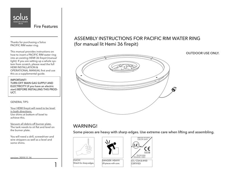
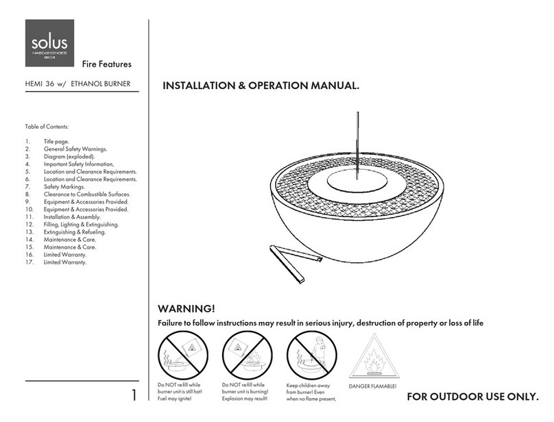
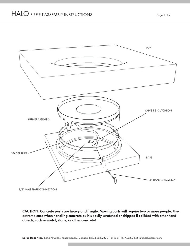
Solus Hemi 26 User manual

fire pit installation and user manual
C O N T E N T S
Standards
Page 2
Product Ratings
Page 2
Product Warnings
Page 3
Location of the Fire Pit
Page 6
Fire Pit Clearances
Page 7
Unpacking
Page 7
General Lifting Guide
Page 8
Installation and Operation
Page 10
Media Installation
Page 16
General Care and Maintenance
Page 18
End of the Season Checklist
Page 21
Start of the Season Checklist
Page 22
Troubleshooting
Page 23
Warranty Information
Page 25
Parts List
Page 27
Optional Accessories
Page 28
Product Registration
Page 31
January 2022

This user manual contains information that is critical to the installation and
operations of your Solus Fire Pits. For safety, please follow these instructions carefully.
This fire pit conform to the following standards:
ANSI Z21.97 – 2004 / CSA 2.41 -2017
Outdoor Decorative Gas Appliance
CSA 2.17-2017
Gas-Fired Appliances For Use at High Altitudes
CE BS EN 498:2012
Specification for Dedicated Liquefied Petroleum Gas Appliances
CE BS EN 509:2001 + A1 : 2003 + A2: 2004
Decorative Fuel-Effect Gas Appliances
Made in Canada by Solus Decor Inc.
Building C-109 Braid Street, New Westminster, BC Canada V3L5H4
1.877.255.3146 www.solusdecor.com
PRODUCT RATINGS
GAS RATINGS
Natural Gas (NG)
Inlet Gas Pressure : 7 ”W.C. (17.4mbar) (0.25 PSi)
Manifold Gas Pressure :
Burner Ratings Minimum Manifold Pressure Requirement
60,000 BTU (17.58kW) 3.5”W.C. (8.7mbar) (0.12 PSi)
73,500 BTU (21.39kW) 3.5”W.C. (8.7mbar) (0.12 PSi)
108,000 BTU (31.65kW) 2.5”W.C. (6.2 mbar) (0.09 PSi
ELECTRICAL RATINGS
North America
: 120vAC, 60Hz, 1.5 Amp
Operating Ranges : 108vAC - 132vAC
UK/EU :
230vAC, 50Hz, 1.5 Amp
Operating Ranges : 220vAC - 240vAC for
UK/EU
WARNINGS:
Consistent
Inlet Gas Pressure
is required to avoid weak pilot flame and burner dropouts.
Stable
Voltage Supply
is required to avoid ignition module lockout.
Page 2 of 32

PRODUCT WARNINGS
DANGER: If you smell gas:
1) Shut off gas to the appliance.
2) Extinguish any open flame.
3) If the odor continues, keep away from appliances and immediately call the gas
supplier or fire department.
WARNING: For Outdoor Use Only
WARNING: Only Licensed Gas Fitters and Electricians are allowed to install and
perform repair services on this fire pit
WARNING: This Fire pit should be inspected before use and at least once annually by a
qualified technician.
WARNING: This manual contains information critical to the safe installation and
operation of the fire pit
WARNING: Never alter product or configuration in any way
WARNING: Fuel line sizing and or/regulations are the responsibility of the installer and
must be able to supply the stated Product Ratings.
WARNING:Testing for leaks after installation is the responsibility of the installer.
WARNING: All fire pits must have a gas shutoff outside of the exterior of the fire pit
to allow for emergency shut off and maintenance.
Page 3 of 32

WARNING: All fire pits with an electric start system, must have an electrical shut off
(wall switch or breaker) on the exterior of the fire pit or on an adjacent wall to allow for
emergency shutdown and maintenance.
WARNING: Improper installation, adjustment, alteration, service, or maintenance can
cause injury or property damage. Read the installation, operating, and maintenance
instructions thoroughly before installing or servicing this equipment
WARNING: Improper installation, adjustment, alteration, service, or maintenance can
cause injury or property damage. Read the installation, operating, and maintenance
instructions thoroughly before installing or servicing this equipment
WARNING: Improper installation, adjustment, alteration, service, or maintenance can
cause injury or property damage. Read the installation, operating, and maintenance
instructions thoroughly before installing or servicing this equipment.
WARNING: Do not use this fire pit if any part of it has been under water. Call a
licensed technician to inspect the fire pit and replace the parts under water as
necessary
WARNING: Do not store or use gasoline or other flammable near the fire pit.
WARNING: It is the installer’s responsibility to ensure a safe installation and to
educate the end user about proper operation. Leave this manual with the end user
WARNING: FOR REMOTE CONTROL USE: To prevent accidental start-up from
unwanted RF signals it is the responsibility of the end user to turn off power to the
electric outlet for the remote control receiver when the fire-pit is not in use via wall
switch or breaker.
WARNING: This fire pit is not intended to be a starter for wood or any other
combustibles.
WARNING: Select a location where the fire pit can be attended during operation.
Never leave an operating fire pit unattended or by someone not familiar with its
operation or emergency shut off locations.
WARNING: Both children and adults should be alerted to the hazards of high surface
temperatures and should stay away to avoid burns and clothing ignition.
WARNING: Young children should be carefully supervised when they are in the area
of the fire pit.
WARNING: Clothing or other flammable materials should not be placed on or near a
fire pit.
Page 4 of 32

WARNING: This fire pit emits very high temperatures - Combustibles must be located
far enough away that there is no risk of ignition.
WARNING: All Solus vessels for Natural and Liquid Propane Gas are vented at the
bottom. The ventilation allows for heat and/or residual fuel to escape. The vents also
function as a drain to prevent water build-up. These vents must not be blocked or
tampered with at any time. Failure to follow this instruction may result in the fire-pit
overheating or explosion. Overheating could also lead to heat damage to internal
components.
WARNING: The interior void space of the Solus vessel surrounding the gas valve and
electrical box cannot be filled with any material (gravel, crushed rock, concrete, etc.) to
allow for proper ventilation.
WARNING: Solus concrete vessels are HEAVY. Use care and caution during lifting,
positioning and repositioning to prevent injury, damage to fire pits and damage to
property. Some Fire Pits will require 2 or more people to lift; some may require 4 or
more people. The Fire Pit must be evenly supported and level – Shim appropriately as
required.
WARNING: The fire pit must be serviced annually by a professional certified in your
jurisdiction.
WARNING: Installer must confirm the appliance is built for the appropriate gas used –
natural gas or LP. Do not use natural gas appliances with LP or LP appliances with
natural gas. Refer to the label on the appliance.
WARNING: To prevent damage, unhook the fire pit from the gas supply for pressure
leak tests.
WARNING: Gas Plumbing Connections: Use only joint compound or tape that is
resistant to all gases. Apply joint compound to all male pipe fittings only- DO NOT use
on FLARED fittings. Be sure to tighten every joint securely.
WARNING: An LP-cylinder not connected for use shall not be stored in the vicinity of
this or any other appliance
Page 5 of 32

LOCATION OF THE FIRE PIT
All Solus Decor fire pits are intended and designed for Outdoor Use Only.
Stable Surface
The Solus fire pit vessel must be placed on a stable and flat surface. Select a location with good
drainage that allows easy access for installation and maintenance of the fire pit.
Consider the location with less unfavorable winds
Solus Burner is designed to withstand 10MPH (16.0934KPH) wind speed. Consider purchasing a
Solus WindShield if the location is prone to severe and unpredictable wind activities like open
beachfront spaces or high rise building patios and balconies.
Page 6 of 32

Gas Shut Off
All Fire pits must have a gas shut-off mechanism located outside of the appliance. This gas shut-off
mechanism must be accessible for emergency shut-off and maintenance. Please note that the Key
Ball Valve outside the vessel of this firepit is not a shut-off mechanism. This Key Ball Valve is used
to regulate the flame height and flame intensity.
Electrical Shut Off
All Fire pits with electronic ignitions must have an External shut-off switch (ON/OFF switch or timer)
near the fire pit. This electrical switch/timer must be accessible for emergency shut-off and
maintenance.
Timer must have a Manual ON/OFF Button.
Please refer to the local electrical and
building codes prior to installation of the switch.
FIRE PIT CLEARANCES
Horizontal Clearance
Concrete vessels must be at least 16 inches (0.5 meter) away from any combustible structure and/or
materials.
Vertical Clearance
Clearance between the burner and any structure overhead must be at least 77 inches (1.95 meter)
from any combustible structure and/or materials.
UNPACKING
Page 7 of 32

The fire pit will arrive in an exquisite crate, fully foamed padded. Carefully inspect the crate for
damages during delivery. Open the crate immediately if any damages are observed. Document the
damages through photographs and report to Solus Decor at once.
Crate Check
Customers are required to report any crate damages within 24 hours of receiving the crates.
Contents Check
Furthermore, it is the customer's responsibility to check it’s contents within 48 hours from receipt
of the shipment to check for content damages.
Solus is not responsible for damages reported beyond these timelines.
GENERAL LIFTING GUIDE
WARNING:
These concrete products are heavy and bulky. Moving these concrete products may require multiple
people. Refer to the table on the next page.
Please note that only Hemi 36 and 48 bowls are provided with straps that act like a carrying
harness.
Page 8 of 32

Product Type
Lbs
Kgs
Number of Person Needed to Lift
Hemi 26
81
37
2
Hemi 36
156
71
2 (Strap Attached)
Hemi 48
317
144
4 (Strap Attached)
Halo 36 Low Base
76
35
2
Halo 36 Low Top
244
111
2-3
EHA 36 Box
230
105
2-3
EHA 36 Top
244
111
2-3
Halo Low 48 Base
75
34
2
Halo Low 48 Top
526
239
5
EHA 48 Box
230
105
2
EHA 48 Top
526
239
4-5
Fire Table Base
74
34
2
Fire Table Box
243
110
2-3
Fire Table Top
134
61
2
Firebox 30
243
110
2-3
Firecube with Lid
156
71
2
Tavolo Base
75
34
2
Tavolo Box
243
110
3-4
Tavolo Top
410
186
4
Linear
148 per slab
67 per slab
2
Page 9 of 32

INSTALLATION AND OPERATION
WARNING:
Installation and repair must be done by Licensed Gas Fitters. The fire pit must be inspected before
use and at least checked or serviced annually by a qualified service technician. Cleaning may be
required frequently as necessary. When a fire pit is not in use, an all-weather cover or metal top
must be used to avoid water and moisture build-up and to protect the fire pit from environmental
hazards.
●
Fire Pit Ratings :
Check the Output BTU Ratings of the fire pit and ensure the
following requirements are followed.
Gas Rating (NG) :
Inlet Gas Pressure : 7 ”W.C. (17.4mbar) (0.25 PSi)
Manifold Gas Pressure :
Burner Ratings Minimum Manifold Pressure Requirement
60,000 BTU (17.58kW) 3.5”W.C. (8.7mbar) (0.12 PSi)
73,500 BTU (21.39kW) 3.5”W.C. (8.7mbar) (0.12 PSi)
108,000 BTU (31.65kW) 2.5”W.C. (6.2 mbar) (0.09 PSi
Electrical Rating
North America
:120vAC, 60Hz, 1.5 Amp
Operating Ranges : 108vAC - 132vAC
EU/UK : 230vAC, 50Hz, 1.5 Amp
Operating Ranges : 220vAC - 240vAC for EU/UK
●
Inlet Pressure :
This is the input gas pressure coming from the main gas line
going to the fire pit. Reading must be taken only after all other gas appliances
on the main supply are on and running at full capacity.
●
Manifold Pressure:
This is the pressure at the manifold when the burner is on.
Page 10 of 32

●
Gas Requirement :
Consistent
Inlet Gas Pressure
is required to avoid weak
pilot flame and burner dropouts.
THIS IS AN ABSOLUTE PRIORITY
.The
reading must be recorded and written on the installer’s card and must be given
to the owner/end user. Owner’s must keep this card for future use and
servicing.
●
Electrical Requirement :
Stable
Voltage Supply
is required to avoid ignition
module lockout.
Page 11 of 32

Locate all the components
●Installer’s Package
●3” Valve Keys
●1/2” Yellow Flex Line
●Auto Burner Assembly with Dual Gas Valve
●Concrete Bowl – Ball Valve
Page 12 of 32

Gas Connection
●Make sure that the gas shut-off valve (emergency shut-off valve) of the appliance is
closed when connecting the gas lines.
●Locate the Ball Valve inside the concrete bowl/vessel. This valve is supplied with flared
fitting at both ends.
●Connect the one end of the yellow flex gas line (supplied) to the one end of the Ball Valve
and the other end to the Dual Solenoid Gas Valve (underneath the burner assembly).
●Connect the end of the NG main supply line to the end of the Ball Valve.
●Test all gas piping and connections for leaks after gas connections
●Do not use an open flame to check for leaks.
Electrical Connection
●Make sure the electrical switch/timer is off.
●In the Electronic Box, take the cover screws off to access the electronic panel.
●Run the supply line from the shut-off switch/timer through the pre-drilled holes at the
bottom of the box.
●Follow the wiring diagram on the next page.
Page 13 of 32

Operation
Turning ON the Electronic Ignition System - NG
○Read instructions very carefully.
○Remove any covers prior to operation.
○Confirm that the gas shut-off valve (emergency shut-off valve) is open.
○Locate the Ball Valve and the electrical shut-off switch/timer.
Page 14 of 32

Ignition
By using the 3” Key (supplied), fully open the Ball Valve freely by turning the shaft
counter-clockwise. Turn on the electrical shut-off switch/timer (not supplied) to initiate
electronic ignition operation. The sparker will try to ignite the pilot for about 7 seconds
until it is lit. Once the pilot is lit, the thermosensor is heated and sends a signal to the
main gas valve to initiate release of gas to the main burner. Fully purged gas lines will
light up the burner manifold immediately.
Purging the line
Failure of the system to detect gas flow and flame after the first ignition cycle will
result in the system going to stand-by mode. Sometimes, due to in-activity and not being
used, bleeding or purging of air out of the lines is needed to encourage gas flow. To do
this, the system needs to be restarted several times until the whole gas line is saturated
with gas. To restart the system, turn on the electrical switch and initiate the ignition
process. Once the sparker stops igniting the pilot, turn the switch off, and then on again
to initiate another ignition cycle. Do this until the pilot is lit and the burner manifold
starts to gather flame.
Flame Adjustment
Adjust the flame height and intensity by turning the Ball Valve using a 3” key
(provided). Turn the key clockwise to decrease and turn anti-clockwise to increase flame
height. Please note that the Ball valve must be fully open prior to ignition and must be
fully closed when not in operation.
Turning OFF the Electronic Ignition System - NG
○Turn the electrical switch/timer off
○Shut the Ball Valve off by turning the shaft clockwise using the 3” Key
○Close the gas shut-off valve (emergency shut-off valve).
○Allow the burner to cool down before installing the cover, if available.
WARNINGS:
Consistent Inlet Gas Pressure is required to avoid weak pilot flame and burner dropouts.
Stable Voltage Supply is required to avoid ignition module lockout.
Page 15 of 32

MEDIA INSTALLATION
WARNING:
Do not install any refractory stones (decorative river rocks) or lava rocks that are not supplied by
Solus Decor. Landscape stones and other natural materials may explode when heated
.
WARNINGS:
Do not dump media over the burner and or the nozzles.
Keep the pilot cage free and clear of any refractory stones and lava rocks.
Page 16 of 32

WARNING:
Improper media installation may cause regressed pilot flame, burner ignition issue or can damage the
thermocouple and thermosensor.
Lava Rock Bed
Cover the entire burner plate with lava rock. Add enough layers of lava rocks until it reaches the
underside of the burner.
Do not cover the nozzles with lava rocks.
Make sure no dust or other
particles are inside the nozzles prior to lighting. When a fire pit is equipped with a Pilot Assembly,
make sure that there are no lava rocks inside the pilot cage.
Refractory Stone Placement
A small pool of decorative river rocks should be placed on and around the burner. Make sure that no
rocks are blocking any of the burner nozzles. Rearrange these stones around to deflect flame into a
natural appearance, this is referred to as Flame Sculpting.
Page 17 of 32

GENERAL CARE AND MAINTENANCE
KEEP THE FIRE PIT COVERED WHEN NOT IN USE
Ensure that gas and power (when applicable) are shut off and the fire pit is cool before performing
any service and maintenance.
We recommend that a qualified service technician performs the following maintenance procedure at
the beginning of each fire pit season.
Cleaning the Burner Nozzles
Periodic check, inspection and cleaning of the burner assembly is recommended. This is to avoid
unusual and unwanted flame behaviour as well as ignition failure. To clean the burner nozzles,
remove the refractory stones and lava rocks to allow access to the burner. Use a scotch green pad
or 320 grit sandpaper or a brush to scrape soot and remove any dust, spider web or any particles.
To check for nozzle clogs, use a small paper clip or needle and carefully insert in the burner nozzles.
Remove any clogs if any.
Page 18 of 32

Cleaning of Pilot Assembly
A clean and clear pilot assembly is important to the operation of the fire pit. Pilot not lighting, gas
valve not opening, gas flow not initiating, flame dropouts, to name a few are common occurrences
of a dirty and un-maintained pilot assembly. Hence regular inspection and maintenance is
recommended.
Components of the Pilot Assembly
1. Pilot Nozzle
Remove the pilot cage carefully. By using a knife or any sharp blade, remove any build-up along the
1/16” slit of the nozzles. Purge the debris or dust off using compressed air or using a vacuum
cleaner.
Page 19 of 32

2. Inlet Orifice
The Pilot Orifice can be removed from the bottom of the pilot assembly (bottom of burner plate)
using a 7/16 wrench. Clean the two (2) tiny holes on top of the Inlet Orifice and ensure that you can
see through the 2 tiny holes.
3. Thermosensor
Use a scotch green pad or 320 grit sandpaper to buff and clean the tip of metal stem of the
thermosensor
Page 20 of 32
This manual suits for next models
19
Table of contents
Other Solus Outdoor Fireplace manuals
Popular Outdoor Fireplace manuals by other brands
Endless Summer
Endless Summer GAD15275MG owner's manual
Axxonn
Axxonn FT150PWISMLID Assembly instructions
Masport
Masport MAWSON ONE Assembly & Usage Instructions
Cosi
Cosi Cosiflow square User and installation instructions
Sunnydaze
Sunnydaze KF-EN36 Assembly instruction sheet

Sunnydaze Decor
Sunnydaze Decor FSN-700 manual
