Solvimus MBUS-REP User manual

MBUS-REP -USER MANUAL
solvimus GmbH –Ratsteichstr. 5 –98693 Ilmenau –Germany
Phone: +49 3677 7613060 –Fax: +49 3677 7613069 –Email: info@solvimus.de
...we solve. www.solvimus.de
MBUS-REP
REPEATER FOR THE
M-BUS
Version 1.2
Date: 2019-05-21
Author:
Sven Ladegast
solvimus GmbH
Ratsteichstr. 5
98693 Ilmenau
Germany

MBUS-REP - User manual
Page 2/11 Version 1.2 Sven Ladegast, 2019-05-21
MBUS_REP500_UG_1.2_EN.docx Released © solvimus GmbH
This page is left blank intentionally.

MBUS-REP - User manual
Sven Ladegast, 2019-05-21 Version 1.2 Page 3/11
© solvimus GmbH Released MBUS_REP500_UG_1.2_EN.docx
Contents
1General hints and conventions....................................................................................................................................4
1.1 About this document.............................................................................................................................................4
1.2 Legal bases .................................................................................................................................................................4
1.2.1 Copyright ..........................................................................................................................................................4
1.2.2 Personnel qualifications .............................................................................................................................4
1.2.3 Technical condition of specified devices............................................................................................4
1.3 Symbols........................................................................................................................................................................4
1.4 Font conventions.....................................................................................................................................................5
1.5 Number notation.....................................................................................................................................................5
1.6 Safety guidelines......................................................................................................................................................5
1.7 Scope.............................................................................................................................................................................6
1.8 Abbreviations............................................................................................................................................................6
1.9 Versions........................................................................................................................................................................6
2General Information .........................................................................................................................................................7
2.1 Device variants..........................................................................................................................................................7
2.2 Connectors .................................................................................................................................................................8
2.3 State LEDs....................................................................................................................................................................8
3Bringing into service.........................................................................................................................................................9
3.1 Extending an existing M-Bus with a new bus segment .........................................................................9
3.2 Ripping up an existing M-Bus ............................................................................................................................9
4Troubleshooting.............................................................................................................................................................. 10
4.1 Hardware error....................................................................................................................................................... 10
4.1.1 The devices does not respond.............................................................................................................. 10
4.1.2 Current consumption is too high (M-Bus slave side).................................................................. 10
4.1.3 Current consumption is too high (24 VDC power supply side) ............................................. 10
5Technical data .................................................................................................................................................................. 11
5.1 General characteristics ....................................................................................................................................... 11
5.1.1 Physical dimensions / weight................................................................................................................ 11
5.1.2 Installation / Storage................................................................................................................................. 11
5.2 Electrical characteristics..................................................................................................................................... 11
5.2.1 Power Requirements ................................................................................................................................ 11
5.2.2 Communication interfaces..................................................................................................................... 11

MBUS-REP - User manual
Page 4/11 Version 1.2 Sven Ladegast, 2019-05-21
MBUS_REP500_UG_1.2_EN.docx Released © solvimus GmbH
1General hints and conventions
1.1 About this document
This manual provides guidance and procedures for a fast and efficient installation and start-up of
the units described in this manual. It is imperative to read and carefully follow the safety guidelines.
1.2 Legal bases
1.2.1 Copyright
This manual, including all figures and illustrations, is copyright-protected. Any further use of this
manual by third parties that violate pertinent copyright provisions is prohibited. Reproduction,
translation, electronic and phototechnical filing/archiving (e.g. photocopying) as well as any
amendments require the written consent of solvimus GmbH.
Non-observance will involve the right to assert damage claims.
The solvimus GmbH reserves the right to provide for any alterations or modifications that serve to
increase the efficiency of technical progress. All rights arising from the granting of patents or from
the legal protection of utility patents are owned by the solvimus GmbH. Third-party products are
always mentioned without any reference to patent rights. Thus, the existence of such rights cannot
be excluded.
1.2.2 Personnel qualifications
The use of the product described in this manual requires special personnel qualifications. All
responsible persons have to familiarize themselves with the underlying legal standards to be
applied, i.e.:
•Valid standards
•Handling of electronic devices
The solvimus GmbH does not assume any liability whatsoever resulting from improper handling
and damage incurred to both, solvimus own and third-party products, by disregarding detailed
information in this manual.
1.2.3 Technical condition of specified devices
The supplied components are equipped with hardware and software configurations, which meet
the individual application requirements. Changes in hardware, software and firmware are permitted
exclusively within the framework of the various alternatives that are documented in the specific
manuals. The solvimus GmbH will be exempted from any liability in case of changes in hardware or
software as well as to non-compliant usage of components.
Please send your request for modified and new hardware or software configurations directly to the
solvimus GmbH.
1.3 Symbols
Danger: Always observe this information to protect persons from injury.
Warning: Always observe this information to prevent damage to the device.
Attention: Marginal conditions that must always be observed to ensure smooth and
efficient operation
ESD (Electrostatic Discharge): Warning of damage to the components through electrostatic
discharge. Observe the precautionary measure for handling components at risk of
electrostatic discharge.
Note: Make important notes that are to be complied with so that a trouble-free and efficient
device operation can be guaranteed.

MBUS-REP - User manual
Sven Ladegast, 2019-05-21 Version 1.2 Page 5/11
© solvimus GmbH Released MBUS_REP500_UG_1.2_EN.docx
Additional information: References to additional literature, manuals, data sheets and
internet pages.
1.4 Font conventions
Names of paths and data files are marked in italic-type. According to the system, Slashes or
Backslashes are used.
i.e.:
D:\Data\
Menu items are marked in italic-type, bold letters.
i.e.:
Save
Sub-menu items or navigation steps within a web browser are marked by using an arrow between
two menu items or tabs.
i.e.:
File
→
New
Pushbuttons or input fields are marked with bold letters.
i.e.: Input
Keys are marked with bold capital letters within angle brackets.
i.e.: <F5>
The print font for program codes is Courier.
i.e.: END_VAR
Names of variables, designators and configuration fields are marked in italic-type.
i.e.:
Value
1.5 Number notation
Numbers are noted according to this table:
Number code
Example
Note
Decimal
100
Normal notation
Hexadecimal
0x64
C Notation
Binary
'100'
in quotation marks
'0110.0100'
nibbles separated with dot
Table 1: Numbering systems
1.6 Safety guidelines
All power sources to the device must always be switched off before carrying out any
installation, repair or maintenance work.
Replace any defective or damaged devices/modules (i.e. in the event of deformed contacts), as the
functionality of the devices cannot be ensured on a long-term basis.
The components are not resistant against materials having seeping and insulating characteristics.
Materials like e.g. aerosols, silicones, triglycerides (found in some hand creams) belong to this group.
If it cannot be ruled out that these materials appear in the component environment, then the
components must be installed in an enclosure that is resistant against the above mentioned
materials.
Clean tools and materials are generally required to operate the device/module.
Only use a soft, wet cloth for cleaning. Soapy water is allowed. Pay attention to ESD.
Do not use solvents like alcohol, acetone etc. for cleaning.
Do not use contact sprays, which could possibly impair the functioning of the contact area
and may cause short circuits.

MBUS-REP - User manual
Page 6/11 Version 1.2 Sven Ladegast, 2019-05-21
MBUS_REP500_UG_1.2_EN.docx Released © solvimus GmbH
Components, especially OEM modules, are designed for the mounting into electronic
housings. Those devices shall not be touched when powered or while in actual operation.
The valid standards and guidelines applicable for the installation of switch cabinets shall be
adhered to.
The devices are equipped with electronic components that may be destroyed by
electrostatic discharge when touched. It is necessary to provide good grounding to
personnel, working environment and packing. Electroconductive parts and contacts should
not be touched.
1.7 Scope
This manual describes the devices mentioned in the title, supplied by solvimus GmbH, Ilmenau.
1.8 Abbreviations
Abbreviation
Description
DIN
Deutsches Institut für Normung,German standardization body
ESD
ElectroStatic Discharge
LED
Light-Emitting Diode
M-Bus
Meter-Bus (EN 13757,part 2 - 3)
OEM
Original Equipment Manufacturer
VDE
Verband der Elektrotechnik Elektronik Informationstechnik e.V.,association for electrical,electronic & information
technologies
wM-Bus
Wireless Meter-Bus (EN 13757,part 3 - 4)
Table 2: Abbreviations
1.9 Versions
Version
Date
Editor
Changes
1.0
2017-07-18
Sven Ladegast
Initial version.
1.1
2017-08-31
Sven Ladegast
Corrected several paragraphs.
1.2
2018-01-19
Sven Ladegast
Modified layout of this document.
1.2
2019-05-21
Romy Schneider
Added MBUS-REP250 in device variants
Table 3: Versions of this document

MBUS-REP - User manual
Sven Ladegast, 2019-05-21 Version 1.2 Page 7/11
© solvimus GmbH Released MBUS_REP500_UG_1.2_EN.docx
2General Information
The M-Bus (Meter-Bus) is an established and well known interface for automated meter reading.
Especially the ease of installation (simple two-wire system with powering by the bus) and the
robustness are important features. These are also special attributes that are of interest for use in
industrial environments.
The M-Bus is defined in the standard EN 13757. There is an own physical layer as well as an own
protocol. For connecting it to other systems a translation is necessary.
The MBUS-Rep acts as an M-Bus master as well as an M-Bus slave. It is fully transparent to the baud
rate that is used on the M-Bus and on-the-fly baud rate changes are supported by the device. By the
use of the MBUS-REP it is possible to extend an existing M-Bus with further units sharing the same
M-Bus installation. The device will supply power for up to 500 UL on the extended M-Bus segment
depending on the device variant.
The MBUS-REP comes in a 3 U enclosure (modules) and is intended for DIN rail mounting (standard
35 mm DIN rail).
2.1 Device variants
The MBUS-REP is a modular designed gateway. As different variants are available, it is possible to
use the configuration which fits best to the application.
Variant
Order number
M-Bus interface
MBUS-REP125
500414
Max.125 unit loads
MBUS-REP250
500417
Max.250 unit loads
MBUS-REP500
500402
Max.500 unit loads
Table 4: Available variants
MBUS-REP - User manual
Page 8/11 Version 1.2 Sven Ladegast, 2019-05-21
MBUS_REP500_UG_1.2_EN.docx Released © solvimus GmbH
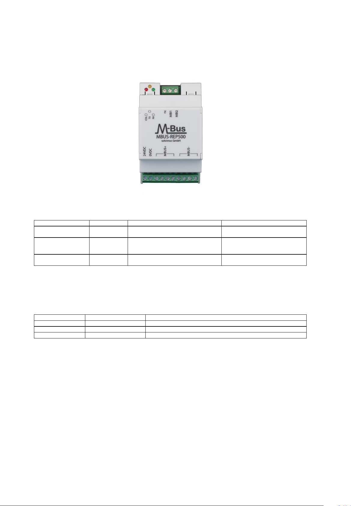
2.2 Connectors
The interface and connectors of the MBUS-REP are available on different sides of the device.
The following figure shows the device:
Figure 1: MBUS-REP500
The MBUS-REP is equipped with the following connectors:
Connector
Marking
Pinning
Remark
Power supply
24VDC,
0VDC
24VDC:12 - 36 VDC
0VDC:Reference ground
Screw clamps
Cross sectional area 2,5 mm²
M-Bus connectors
(master side)
MBUS+,
MBUS-
MBUS+:M-Bus positive bus line
MBUS-: M-Bus negative bus line
Screw clamps
Cross sectional area 2,5 mm²
MBUS+ and MBUS- are shorted each
M-Bus connectors
(slave side)
MBI1,MBI2,
nc
MBI1,MBI2:Bus lines of the M-Bus to extend
nc:Not connected
Screw clamps
Cross sectional area 2,5 mm²
Table 1: Connectors
2.3 State LEDs
The MBUS-REP is equipped with 3 state LEDs. These LEDs visualize the operational state of the
device:
LED
Color
Description
COL
red
Lights up when a collision has been detected on the M-Bus
TX
yellow
Lights up when the M-Bus master is transmitting to the M-Bus
RX
green
Lights up when data is received from M-Bus slaves
Table 2: State LEDs

MBUS-REP - User manual
Sven Ladegast, 2019-05-21 Version 1.2 Page 9/11
© solvimus GmbH Released MBUS_REP500_UG_1.2_EN.docx
3Bringing into service
De-energize the M-Bus or whose master respectively before connecting the device.
Please connect the slave connectors (MBI1 and MBI2, see section 2.2) of the MBUS-REP
exclusively to the bus segment of the M-Bus that is powered by the original M-Bus master.
Not doing so will damage the device.
The MBUS-REP is completely transparent to the data communication on the M-Bus. In this manner
the device is not visible as an M-Bus slave and baud rate changes of the M-Bus master do not need
any user interaction.
3.1 Extending an existing M-Bus with a new bus segment
Connect the bus lines of the existing M-Bus to the terminals MBI1 and MBI2.
The new M-Bus segment shall be connected to the terminals MBUS+ and MBUS- (see section 2.2).
The MBUS-REP is able to supply this new bus segment with 125 or 500 UL respectively by only
drawing 2 UL from the M-Bus on its slave connectors (MBI1 & MBI2).
Connect the power supply terminals 24VDC and 0VDC with a suitable DC power supply.
3.2 Ripping up an existing M-Bus
Do rip up the M-Bus at an appropriate position. Please make sure to distribute the devices and unit
loads according to the drive power of the M-Bus master(s).
Connect the bus lines that are connected to the original M-Bus master to the terminals MBI1 and
MBI2 (see section 2.2).
The second M-Bus segment is now powered by the MBUS-REP and goes to the terminals MBUS+
and MBUS- (see section 2.2). The MBUS-REP is able to supply this new bus segment with 125 or
500 UL respectively by only drawing 2 UL from the M-Bus on its slave connectors (MBI1 & MBI2).
Connect the power supply terminals 24VDC and 0VDC with a suitable DC power supply.

MBUS-REP - User manual
Page 10/11 Version 1.2 Sven Ladegast, 2019-05-21
MBUS_REP500_UG_1.2_EN.docx Released © solvimus GmbH
4Troubleshooting
In case the MBUS-REP works not as described in this document, it is useful to locate the malfunction
in order to resolve the issue and to recover the full functionality again.
4.1 Hardware error
4.1.1 The devices does not respond
After powering the device it does not operate. Current consumption is about 0 mA.
Please check the following thinks:
•Is there a voltage of about 24 VDC between the terminals 24VDC and 0VDC?
•Is there a voltage of about 40 VDC present between the terminals MBUS+ and MBUS-?
•Is there a voltage of about 20 - 40 VDC between the terminals MBI1 and MBI2?
If errors could not be resolved, please contact our customer support:
email: support@solvimus.de
4.1.2 Current consumption is too high (M-Bus slave side)
Communication stalls after connecting the MBUS-REP to the M-Bus. When supplying a voltage
between 24 and 40 VDC to the terminals MBI1 and MBI2 the current draw exceeds 100 mA.
If errors could not be resolved, please contact our customer support:
email: support@solvimus.de
4.1.3 Current consumption is too high (24 VDC power supply side)
Communication to the extended M-Bus segment stalls after connecting a suitable power supply to
the MBUS-REP. The current draw from the power supply exceeds 1.8 A.
If errors could not be resolved, please contact our customer support:
email: support@solvimus.de

MBUS-REP - User manual
Sven Ladegast, 2019-05-21 Version 1.2 Page 11/11
© solvimus GmbH Released MBUS_REP500_UG_1.2_EN.docx
5Technical data
5.1 General characteristics
5.1.1 Physical dimensions / weight
The housing has the following dimensions:
•Width: 53 mm (3U)
•Height: 89 mm
•Depth: 61 mm
•Weight: approx. 160 g
5.1.2 Installation / Storage
The device is intended for installation in a switch cabinet:
•Storage temperature: -20 –70 °C
•Operating temperature: 0 –55 °C
•Humidity: 10 –95 % relH
•Protection class: IP20
•DIN rail mounting (35 mm DIN rail)
5.2 Electrical characteristics
5.2.1 Power Requirements
The device is powered by an external power supply (see pin assignment at section 2.2):
•Input voltage: 12 - 36 VDC, Screw terminals (≤2,5 mm²)
•Power consumption 24 VDC: max. 40 W
•Power consumption M-Bus: typ. 72 mW, equates to 2 UL (M-Bus)
•Safety: Bipolar M-Bus slave terminals, Reverse voltage protection, over-voltage protection
(transient)
5.2.2 Communication interfaces
The MBUS-REP comes with an M-Bus slave interface and an M-Bus master interface (see pin
assignment at section 2.2)
•Conform to EN 13757-2/-3
•Baud rate: 300-9600 Baud
Other manuals for MBUS-REP
1
This manual suits for next models
6
Table of contents
Other Solvimus Repeater manuals


