Solvimus MBUS-REP User manual

MBUS-REP - USER MANUAL
MBUS-REP
Repeater
for the M-Bus
Version: 1.3
Date: 6 December 2022
Authors:
Remo Reichel, Frank Richter
solvimus GmbH
Ratsteichstr. 5
98693 Ilmenau
Germany
solvimus GmbH – Ratsteichstr. 5 – 98693 Ilmenau – Germany

MBUS-REP - User manual
Page intentionally left blank
Page 2/15
UG_EN_MBUS-REP.pdf
Version: 1.3
Released
Frank Richter, 6 December 2022
©solvimus GmbH

MBUS-REP - User manual
Table of Contents
Table of Contents 3
1 Notes and conventions 4
1.1 Aboutthisdocument ....................................... 4
1.2 Legalbasis............................................. 4
1.2.1 Placingonthemarket................................... 4
1.2.2 Copyrightprotection ................................... 4
1.2.3 Personnelqualification .................................. 4
1.2.4 Intendeduse........................................ 4
1.2.5 Exclusionofliability.................................... 4
1.2.6 Disclaimer......................................... 4
1.3 Symbols .............................................. 5
1.4 Fontconventions ......................................... 5
1.5 Numbernotation ......................................... 5
1.6 Safetyguidelines.......................................... 6
1.7 Scope ............................................... 6
1.8 Abbreviations ........................................... 6
2 Introducing the device 9
2.1 Generalinformation ........................................ 9
2.2 Delivery variants and scope of delivery . . . . . . . . . . . . . . . . . . . . . . . . . . . . . . 9
2.3 Connectors............................................. 9
2.4 StatusLEDs............................................ 10
2.5 Firststeps ............................................. 10
2.5.1 SignallingontheM-Bus ................................. 10
2.5.2 Extending an existing M-Bus network with a new bus segment . . . . . . . . . . . . . 12
2.5.3 Ripping up an existing M-Bus network . . . . . . . . . . . . . . . . . . . . . . . . . . 12
2.6 Specifictroubleshooting...................................... 12
2.6.1 The device does not respond. . . . . . . . . . . . . . . . . . . . . . . . . . . . . . . . 12
2.6.2 The existing master is unable to read the connected meters. . . . . . . . . . . . . . . 12
2.7 Technicaldata........................................... 13
2.7.1 Generalspecifications................................... 13
2.7.2 Electrical specifications . . . . . . . . . . . . . . . . . . . . . . . . . . . . . . . . . . 13
2.7.3 Furtherspecifications ................................... 14
3 Accessory 15
Frank Richter, 6 December 2022
©solvimus GmbH
Version: 1.3
Released
Page 3/15
UG_EN_MBUS-REP.pdf

MBUS-REP - User manual
1 Notes and conventions
1.1 About this document
This manual provides guidance and procedures for a fast and efficient installation and start-up of the units
described in this manual. It is imperative to read and carefully follow the safety guidelines.
1.2 Legal basis
1.2.1 Placing on the market
Manufacturer of the MBUS-REP is the solvimus GmbH, Ratsteichstraße 5, 98693 Ilmenau, Germany.
1.2.2 Copyright protection
This documentation, including all illustrations contained therein, is protected by copyright. The author is
solvimus GmbH, Ilmenau. The exploitation rights are also held by solvimus GmbH. Any further use that
deviates from the copyright regulations is not allowed. Reproduction, translation into other languages, as
well as electronic and phototechnical archiving and modification require the written permission of solvimus
GmbH. Violations will result in a claim for damages. The solvimus GmbH reserves the right to provide for any
alterations or modifications that serve to increase the efficiency of technical progress. All rights in the event
of the granting of a patent or the protection of a utility model are reserved by solvimus GmbH. Third-party
products are always mentioned without reference to patent rights. The existence of such rights can therefore
not be excluded.
1.2.3 Personnel qualification
The product use described in this documentation is intended exclusively for qualified electricians or persons
instructed by these. They must all have good knowledge in the following areas:
•Applicable standards
•Use of electronic devices
1.2.4 Intended use
If necessary, the components or assemblies are delivered ex works with a fixed hardware and software config-
uration for the respective application. Modifications are only permitted within the scope of the possibilities
shown in the documentation. All other changes to the hardware or software as well as the non-intended use
of the components result in the exclusion of liability on the part of solvimus GmbH. Please send any requests
for a modified or new hardware or software configuration to solvimus GmbH.
1.2.5 Exclusion of liability
Study this manual and all instructions thoroughly prior to the first use of this product and respect all safety
warnings, even if you are familiar with handling and operating electronic devices.
The solvimus GmbH accepts no liability for damage to objects and persons caused by erroneous operation, inap-
propriate handling, improper or non-intended use or disregard for this manual, especially the safety guidelines,
and any warranty is void.
1.2.6 Disclaimer
All products, company names, trademarks and brands are the property of their respective holders. Their use
serves only to describe and identify the respective company, product or service. Use of them does not imply
any affiliation with, commercial relationship with or endorsement by them.
Page 4/15
UG_EN_MBUS-REP.pdf
Version: 1.3
Released
Frank Richter, 6 December 2022
©solvimus GmbH

MBUS-REP - User manual
Firefox is a trademark of the Mozilla Foundation in the U.S. and other countries.
Chrome™browser is a trademark of Google Inc.
Microsoft Excel is a trademark of the Microsoft group of companies.
7-Zip Copyright (C) 1999-2022 Igor Pavlov.
Wireshark: Copyright 1998-2022 Gerald Combs <gerald@wireshark.org> and contributors.
1.3 Symbols
Danger: It is essential to observe this information in order to protect persons from injury.
Caution: It is essential to observe this information in order to prevent damage to the device.
Notice: Boundary conditions that must always be observed to ensure smooth and efficient operation.
ESD (Electrostatic Discharge): Warning of danger to components due to electrostatic discharge. Observe
precautionary measures when handling components at risk of electrostatic discharge.
Note: Routines or advice for efficient equipment use.
Further information: References to additional literature, manuals, data sheets and internet pages.
1.4 Font conventions
Names of paths and files are marked in italics. According to the system the notation is using slash or backslash.
e. g.: D: \Data
Menu items or tabs are marked in bold italics.
e. g.: Save
An arrow between two menu items or tabs indicates the selection of a sub-menu item from a menu or a
navigation process in the web browser.
e. g.: File →New
Buttons and input fields are shown in bold letters.
e. g.: Input
Key labels are enclosed in angle brackets and shown in bold with capital letters.
e. g.: ⟨F5⟩
Programme codes are printed in Courier font.
e. g.: ENDVAR
Variable names, identifiers and parameter entries are marked in italics.
e. g.: Value
1.5 Number notation
Numbers a noted according to this table:
Numbering system Example Comments
Decimal 100 Normal notation
Hexadecimal 0x64 C-like notation
Binary ’100’ In apostrophes
’0110.0100’ Nibbles separated by dots
Table 1: Numbering systems
Frank Richter, 6 December 2022
©solvimus GmbH
Version: 1.3
Released
Page 5/15
UG_EN_MBUS-REP.pdf

MBUS-REP - User manual
1.6 Safety guidelines
Observe the recognized rules of technology and the legal requirements, standards and norms, and other
recommendations.
Study the instructions for the extinction of fire in electrical installations.
The power supply must be switched off before replacing components and modules.
If the contacts are deformed, the affected module or connector must be replaced, as the function is not guar-
anteed in the long term.
The components are not resistant to substances that have creeping and insulating properties. These include
e.g. aerosols, silicones, triglycerides (ingredient of some hand creams). If the presence of these substances in
the vicinity of the components cannot be excluded, additional measures must be taken:
•Install the components in an appropriate casing.
•Handle components with clean tools and materials only.
Only use a soft, wet cloth for cleaning. Soapy water is allowed. Pay attention to ESD.
Do not use solvents like alcohol, acetone etc. for cleaning.
Do not use a contact spray, because in an extreme case the function of the contact point is impaired
and may lead to short circuits.
Assemblies, especially OEM modules, are designed for installation in electronic housings. Do not touch
the assembly when it is live. In each case, the valid standards and directives applicable to the construction
of control cabinets must be observed.
The components are populated with electronic parts which can be destroyed by an electrostatic discharge.
When handling the components, ensure that everything in the vicinity is well earthed (personnel, work-
place and packaging). Do not touch electrically conductive components, e.g. data contacts.
1.7 Scope
This documentation describes the device manufactured by solvimus GmbH, Ilmenau, and stated on the title
page.
1.8 Abbreviations
Abbreviation Meaning
2G Mobile radio standard, synonym for GSM or GPRS
3G Mobile radio standard, synonym for UMTS
4G Mobile radio standard, synonym for LTE
ACK Acknowledge
AES Advanced Encryption Standard
AFL Authentication and Fragmentation Layer
AI Analog Input
ANSI American National Standards Institute
AO Analog Output
APN Access Point Name
ASCII American Standard Code for Information Interchange
ASHRAE American Society of Heating, Refrigerating and Air-Conditioning Engineers
BACnet Building Automation and Control networks
BBMD BACnet Broadcast Management Device
BCD Binary-coded decimal numbers
BDT Broadcast Distribution Table
BMS Building Management System
CA Certification Authority
CHAP Challenge Handshake Authentication Protocol
CI Control Information
CLI Command line interface
COSEM COmpanion Specification for Energy Metering
CPU Central processing unit
CRC Cyclic redundancy check
CSV Character-Separated Values
Continued on next page
Page 6/15
UG_EN_MBUS-REP.pdf
Version: 1.3
Released
Frank Richter, 6 December 2022
©solvimus GmbH

MBUS-REP - User manual
Table 2 – Continued from previous page
Abbreviation Meaning
CTS Clear to send
D0 D0 interface (optical interface, IEC 62056-21)
DDC Direct Digital Control
DHCP Dynamic Host Configuration Protocol
DI Digital Input, digital input terminal
DIF Data information field
DIFE Data information field extensions
DIN Deutsches Institut für Normung, German Institute for Standardization
DLDE Direct Local Data Exchange (EN 62056-21, IEC 1107)
DLDERS DLDE communication via RS-232 or RS-485
DLMS Device Language Message Specification
DNS Domain Name System
DO Digital Output, digital output terminal
EEG German Renewable Energy Sources Act
EIA/TIA Electronic Industries Alliance/Telecommunications Industry Association
ELL Extended Link Layer
EMC Electromagnetic compatibility
EN European norm
ESD Electrostatic Discharge
FCB Frame Count Bit
FCV Frame Count Valid Bit
FNN Forum Netztechnik/Netzbetrieb, subgroup of VDE
FSK Frequency Shift Keying
FTP File Transfer Protocol
FTPS FTP via TLS
GB Gigabyte
GMT Greenwich Mean Time
GPRS General Packet Radio Service
GSM Global System for Mobile Communications
HCA Heat cost allocator
HTTP Hypertext Transfer Protocol
HTTPS Hypertext Transfer Protocol Secure
I2C Inter-Integrated Circuit
I/O Input/Output
ICMP Internet Control Message Protocol
ID Identification, Identifier, unique marking
IEC International Electrotechnical Commission
IEEE Institute of Electrical and Electronics Engineers
IoT Internet of Things
IP Internet Protocol or IP address
ISO International Organization for Standardization
JSON JavaScript Object Notation
LAN Local area network
LED Light-Emitting Diode
LSB Least significant byte
LSW Least significant word
LTE Long Term Evolution
M2M Machine-to-Machine
M-Bus Meter-Bus (EN 13757, part 2, 3 and 7)
MAC Medium Access Control or MAC-Adresse
MB Megabyte
MCR Multi Channel Reporting
MDM Meter Data Management
MEI Modbus Encapsulated Interface
MHz Megahertz
MQTT Message Queuing Telemetry Transport
MSB Most Significant Byte
MSW Most Significant Word
MUC Multi Utility Communication, MUC controller
NB-IoT Narrow Band Internet of Things
OBIS Object Identification System
OEM Original Equipment Manufacturer
OMS Open Metering System
PAP Password Authentication Protocol
PEM Privacy Enhanced Mail
PIN Personal Identification Number
PKI Public Key Infrastructure
PLC Programmable Logic Controller
PPP Point-to-Point Protocol
PPPoE Point-to-Point Protocol over Ethernet
PUK Personal Unblocking Key
Continued on next page
Frank Richter, 6 December 2022
©solvimus GmbH
Version: 1.3
Released
Page 7/15
UG_EN_MBUS-REP.pdf

MBUS-REP - User manual
Table 2 – Continued from previous page
Abbreviation Meaning
RAM Random Access Memory
REQ_UD Request User Data (Class 1 or 2)
RFC Requests For Comments
RSP_UD Respond User Data
RSSI Received Signal Strength Indicator
RTC Real-Time Clock
RTOS Real-Time Operating System
RTS Request to send
RTU Remote Terminal Unit
S0 S0 interface (pulse interface, EN 62053-31)
SCADA Supervisory Control and Data Acquisition
SCP Secure Copy
SFTP SSH File Transfer Protocol
SIM Subscriber Identity Module
SML Smart Message Language
SMTP Simple Mail Transfer Protocol
SND_NKE Send Link Reset
SND_UD Send User Data to slave
SNTP Simple Network Time Protocol
SPST Single Pole Single Throw Relay (closing switch)
SRD Short Range Device
SSH Secure Shell
SSL Secure Sockets Layer
TCP Transmission Control Protocol
THT Through-Hole Technology
TLS Transport Layer Security
U Unit width of the housing (1 U = 18 mm)
UART Universal Asynchronous Receiver Transmitter
UDP User Datagram Protocol
UL Unit load for M-Bus
UMTS Universal Mobile Telecommunications System
UTC Universal Time Coordinated
VDE Verband der Elektrotechnik Elektronik Informationstechnik e.V., German association
VHF Very high frequency
VIF Value information field
VIFE Value information field extensions
VLAN Virtual Local Area Network
VPN Virtual Private Network
WAN Wide Area Network
WLAN Wireless Local Area Network
wM-Bus Wireless Meter-Bus (EN 13757, part 3, 4 and 7)
XML eXtensible Markup Language
XSLT eXtensible Stylesheet Language Transformation
Table 2: Abbreviations
Page 8/15
UG_EN_MBUS-REP.pdf
Version: 1.3
Released
Frank Richter, 6 December 2022
©solvimus GmbH

MBUS-REP - User manual
2 Introducing the device
2.1 General information
The M-Bus (Meter-Bus) is an established and well-known interface for automated meter reading. Especially
the ease of installation (simple two-wire system with powering by the bus) and the robustness are important
features. These are also special attributes that are of interest for use in industrial environments.
The M-Bus is defined in the standard EN 13757. It establishes an own physics as well as an own protocol.
The Repeater (in the sequel MBUS-REP for simplicity) acts on the M-Bus as slave and also as master, and
is fully transparent for the communication and with respect to the baud rate. By the use of the MBUS-REP
it is possible to extend an existing M-Bus network with further units. The device will supply power for up to
125, 250 respectively 500 unit loads (UL, mostly equivalent to the number of meters) on the extended M-Bus
segment. The current drawn from the M-Bus at the slave connectors MBI1 and MBI2 (see Section 2.3)
corresponds to 2 UL only.
The MBUS-REP comes in a housing 3-U (modules) wide and is intended for top hat rail mounting (DIN rail
35 mm).
The serial number of the devices of the solvimus GmbH can be read from the housing.
2.2 Delivery variants and scope of delivery
The MBUS-REP is offered in a range of variants, and so can easily be adapted to the requirements of the
particular property.
Variant Order number M-Bus interface
MBUS-REP125 500414 max. 125 unit loads
MBUS-REP250 500417 max. 250 unit loads
MBUS-REP500 500402 max. 500 unit loads
Table 3: Delivery variants
The scope of delivery contains the device and a Quick Start Guide.
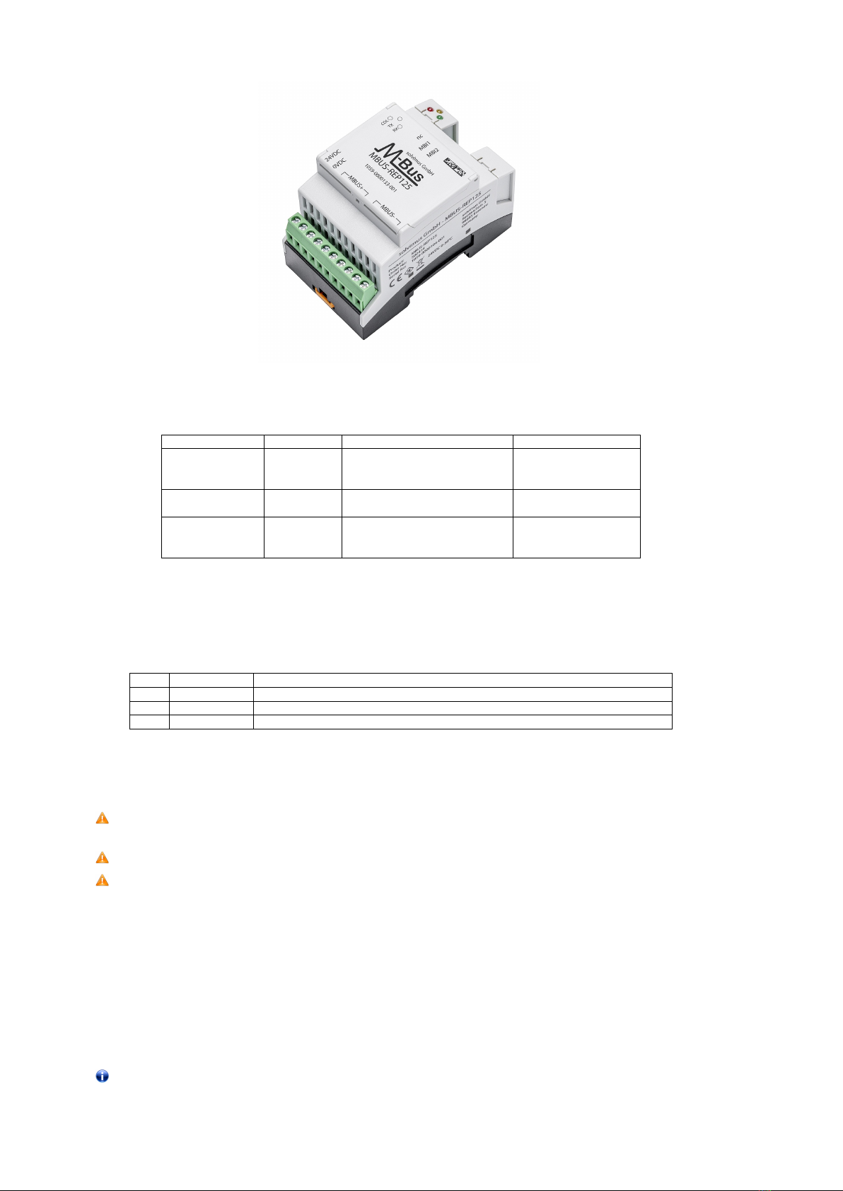
2.3 Connectors
The connectors and interfaces of the MBUS-REP are on the top and bottom sides of the device.
The following figure shows the device. All variants are similar in outward appearance.
Frank Richter, 6 December 2022
©solvimus GmbH
Version: 1.3
Released
Page 9/15
UG_EN_MBUS-REP.pdf
MBUS-REP - User manual
Figure 1: MBUS-REP125
The following connectors are available at the MBUS-REP:
Connector Designation Pin assignment Comments
Power supply 24 VDC 24 VDC: positive power supply 24 VDC: 12-36 VDC
0 VDC 0 VDC: negative power supply screw terminal
cross section 2.5 mm2
M-Bus connector MBUS+ MBUS+: positive bus line screw terminal
(master side) MBUS- MBUS-: negative bus line cross section 2.5 mm2
M-Bus connector MBI1 MBI1: first bus line screw terminal
(slave side) MBI2 MBI2: second bus line cross section 2.5 mm2
nc nc: not connected
Table 4: Pin assignment
2.4 Status LEDs
The MBUS-REP is equipped with 3 status LEDs. These indicate the following states:
LED Colour Description
COL red (flashing) Collision respectively too large capacitive load on the M-Bus
TX yellow Reception of data from the M-Bus master and transmission on the M-Bus
RX green Reception of data from the M-Bus slaves and transmission to the M-Bus master
Table 5: Status LEDs
2.5 First steps
Only trained and appropriately qualified personnel are allowed to check the electric power supply (see
Section 1.2.3).
De-energise the M-Bus or its master before connecting the device.
Connect exclusively the slave connectors (MBI1 and MBI2, see Section 2.3) of the MBUS-REP to the
existing physical master. Otherwise, the device can be damaged.
The MBUS-REP is fully transparent to the data communication on the M-Bus. This means that the device is
not visible as an M-Bus slave and baud rate changes of the M-Bus master do not need any user interaction.
2.5.1 Signalling on the M-Bus
The M-Bus is a single master multiple slave bus. Therefore, a single bus master controls the bus and the data
traffic on the bus. Several slaves, i.e. meters, can be connected to the bus.
A second physical master is not allowed on the M-Bus.
Page 10/15
UG_EN_MBUS-REP.pdf
Version: 1.3
Released
Frank Richter, 6 December 2022
©solvimus GmbH
MBUS-REP - User manual
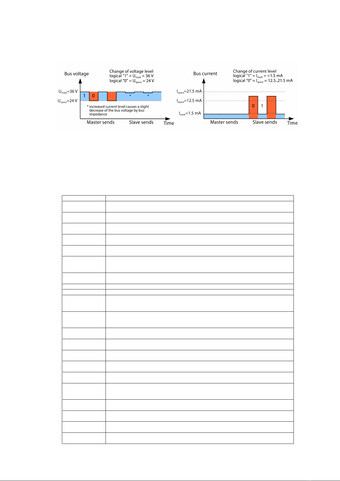
On a physical level, the M-Bus uses voltage and current modulation to transmit data. The master transmits
telegrams by modulating the bus voltage, the slave transmits telegrams by modulating the current through
the bus. This is shown schematically in the following figure (values of current and voltage may deviate):
Figure 2: Signalling on the M-Bus
The M-Bus follows the principle of request-response, i.e. the master initiates the communication by a re-
quest/command which is then answered/confirmed by the slave. Spontaneous data transmission on the part
of the slaves is not allowed.
Certain terms are used in the M-Bus standard. The basics of communication are taken from IEC 60870-5-101.
Key terms are explained in the table below:
Term Description
ACK ACKnowledge, confirmation of a command, transmitted over the M-Bus as a single char-
acter telegram with content 0xE5.
Application reset Reset of the application layer, command to reset the meter to the default state and to
reset the meter for consecutive telegrams (multipaging).
Broadcast Broadcast, command or request is sent to all slaves, special addresses 0xFE and 0xFF are
used.
C-field Command field, code that indicates the direction in which a telegram is exchanged and the
meaning of the telegram.
Checksum Check number for checking transmission errors, the checksum the M-Bus uses, results from
the addition of the transmitted data (without telegram header, up to checksum).
Single character One of the three telegram formats the M-Bus uses with a length of exactly 1 byte, telegram
header and end, consisting of checksum and 0x16, are not present, used on the M-Bus for
ACK.
FCB Frame Count Bit, bit in the C field, which is alternately set to 1 or 0 in consecutive
telegrams, consecutive telegrams can be retrieved when the bit changes in the request.
Imark Transmit current of the slave at logical 1, usually 1 UL.
Ispace Transmit current of the slave at logical 0, usually 12.5-21.5 mA.
Short frame One of the three telegram formats the M-Bus uses with a length of exactly 5 bytes, is only
sent from the master to the slave (e.g. commands and instructions), the telegram header
is 0x10 and the telegram ends with the checksum and 0x16.
Long frame One of the three telegram formats the M-Bus uses with a variable length, the telegram
header consists of 0x68 LL LL 0x68 (LL is the length of the telegram in each case), the
telegram ends with the checksum and 0x16.
Multipaging M-Bus method of distributing large amounts of data into several logically consecutive
telegrams, use of the FCB for sequence control.
Primary address M-Bus Link layer Address, this is used to address the requests/commands, address space
0-250, special addresses 253 (0xFD), 254 (0xFE) and 255 (0xFF).
REQ_UD2 REQuest User Data type 2, request for consumption data, transmitted over the M-Bus by
the master as a short frame telegram.
RSP_UD ReSPond User Data, response of the meter to a request for data, transmitted over the
M-Bus by the slave as a long frame telegram.
Secondary address Worldwide unique identification number of the meter, consisting of manufacturer code,
8-digit serial number, medium ID and version number.
Slave select Procedure for extending the address space to the secondary address of the meter, use of
the SND_UD for selecting the meter via the application layer, then selected meter can be
addressed via special address 0xFD.
Standard load Defined idle current that a meter may draw from the M-Bus, according to the standard
1 UL=1.5 mA.
SND_NKE Send Link Reset, initialization command to the slave (reset FCB bit and selection), trans-
mitted by the master as a short frame telegram on the M-Bus.
SND_UD SeND User data, sending data or commands to the meter, transmitted by the master as a
long frame telegram on the M-Bus.
Umark Mark voltage, upper voltage of the M-Bus signals at the master, representation of the
logical 1, idle state, usually 24-42 V.
Continued on next page
Frank Richter, 6 December 2022
©solvimus GmbH
Version: 1.3
Released
Page 11/15
UG_EN_MBUS-REP.pdf

MBUS-REP - User manual
Table 6 – Continued from previous page
Term Description
Uspace Space voltage, lower voltage of the M-Bus signals at the master, representation of the
logical 0, usually 12-30 V.
UL Unit of standard load (see above)
Table 6: M-Bus specific terms
2.5.2 Extending an existing M-Bus network with a new bus segment
Connect the bus lines of the existing M-Bus to the connectors MBI1 and MBI2 (see Section 2.3).
The new M-Bus segment is to be connected to the connectors MBUS+ and MBUS- (see Section 2.3). The
MBUS-REP is able to supply this new bus segment with up to 125, 250 respectively 500 UL (unit loads).
Connect the power supply connectors 24 VDC and 0 VDC to a suitable power supply.
2.5.3 Ripping up an existing M-Bus network
Rip up the M-Bus at an appropriate position. Make sure to connect at most 125, 250 respectively 500 UL
(unit loads) in each wiring section of the new severed M-Bus.
Connect the bus lines that are connected to the original M-Bus master to the connectors MBI1 and MBI2 (see
Section 2.3).
The second M-Bus segment is to be connected to MBUS+ and MBUS- (see Section 2.3). The MBUS-REP
is able to supply this new bus segment with up to 125, 250 respectively 500 UL (unit loads).
Connect the power supply connectors 24 VDC and 0 VDC to a suitable power supply.
2.6 Specific troubleshooting
In case the MBUS-REP does not work as described in this document, it is useful to locate the malfunction in
order to resolve the issue and to recover the full functionality again.
2.6.1 The device does not respond.
Only trained and appropriately qualified personnel are allowed to check the electric power supply (see
Section 1.2.3).
The device does not respond after powering on. The current consumption is about 0 mA.
Check the power supply:
•Is there a voltage of about 24VDC between the connectors 24VDC and 0VDC?
•Is there a voltage of about 40VDC between the connectors MBUS+ and MBUS-?
•Is there a voltage of about 20-40 VDC between the connectors MBI1 and MBI2?
If errors could not be eliminated, please contact our customer support:
E-Mail: suppo[email protected]
Phone: +49 3677 7613065
2.6.2 The existing master is unable to read the connected meters.
Only trained and appropriately qualified personnel are allowed to check the electric power supply (see
Section 1.2.3).
Checking the M-Bus slave interface
Check if the bus voltage between MBI1 and MBI2 is 20-40 VDC. If it is considerably lower, the bus should
be disconnected and checked again. Also, the current consumption of the slave interface between MBI1 and
MBI2 should be measured. The value should be inferior to 10 mA.
Page 12/15
UG_EN_MBUS-REP.pdf
Version: 1.3
Released
Frank Richter, 6 December 2022
©solvimus GmbH

MBUS-REP - User manual
Checking the M-Bus master interface
Check if the collision LED is flashing red. If so, an overload of the interface is detected. Possible causes are:
•Short circuit between MBUS+ and MBUS-: In this case disconnect all M-Bus wires. The collision LED
should be off now.
–If not, the interface is faulty.
–If it is, then the voltage on the M-Bus should be checked as explained in Section 2.6.1. If it is in
the indicated range, you can try to delimit the cause by connecting individual wires.
•Too many meters connected: the quantity of unit loads that can be connected depends on the Repeater
hardware. Check the meters and their quantity. A meter may require more than one unit load.
If errors could not be eliminated, please contact our customer support:
E-Mail: suppo[email protected]
Phone: +49 3677 7613065
2.7 Technical data
2.7.1 General specifications
Dimensions/Weight
The devices have the following dimensions and the following weight:
•Width: 54 mm
•Height: 90 mm
•Depth: 60 mm
•Weight: approx. 130 g
Mounting
The device is intended for control cabinet mounting:
•Temperature range: 0-55 °C
•Air humidity: 0-95 % relH
•Degree of protection: IP20 (IEC 60529)
•Top hat rail mounting (DIN rail 35 mm, IEC 60715)
2.7.2 Electrical specifications
Power supply
The device is powered by an external power supply (pin assignment see Section 2.3):
•Voltage: 12-36 VDC
•Screw terminals (≤2.5 mm2, tightening torque 0.5-0.6 Nm)
•Power consumption: <1W (idle state), max. 40 W
•Safety: reverse polarity protected M-Bus, overvoltage protection (transients), protection class III (IEC 61140)
•Peak inrush-current: approx. 3 A
Meter interfaces
The device comes with an M-Bus slave interface and an M-Bus master interface (pin assignment see Section 2.3):
•M-Bus master: compliant to EN 13757-2, Umark=40 V, Uspace=27 V, screw terminals (≤2.5 mm2,
tightening torque 0.5-0.6 Nm)
–max. 125 unit loads (UL) for MBUS-REP125
–max. 250 unit loads (UL) for MBUS-REP250
Frank Richter, 6 December 2022
©solvimus GmbH
Version: 1.3
Released
Page 13/15
UG_EN_MBUS-REP.pdf

MBUS-REP - User manual
–max. 500 unit loads (UL) for MBUS-REP500
–Max. current rating permanent: 1500 mA
•M-Bus slave: compliant to EN 13757-2, current consumption approx. 3 mA (2 UL), screw terminals
(≤1.5 mm2, tightening torque 0.5-0.6 Nm)
•Baud rate: 300-9600 bps
2.7.3 Further specifications
Galvanic isolation
M-Bus master and M-Bus slave are galvanically isolated:
•Galvanic isolation: 1000 V
Page 14/15
UG_EN_MBUS-REP.pdf
Version: 1.3
Released
Frank Richter, 6 December 2022
©solvimus GmbH

MBUS-REP - User manual
3 Accessory
The solvimus GmbH recommends the external power supply PHOENIX CONTACT STEP-PS/1AC/24DC/1.75,
order number of the solvimus GmbH: 103960.
The usage of accessories not recommended is at your own risk. It is imperative to mind Section 1.2.5.
Frank Richter, 6 December 2022
©solvimus GmbH
Version: 1.3
Released
Page 15/15
UG_EN_MBUS-REP.pdf
Other manuals for MBUS-REP
1
Table of contents
Other Solvimus Repeater manuals


