SOMA ORNAMENT-8 User manual
USER
MANUAL

ORNAMENT•8 USER MANUAL
GENERAL REVIEW
ORNAMENT‑8 is an analog synthesizer of behavior for creating complex rhythmic patterns
and control signals. Since it inherits and further develops the principles laid down in the
LYRA•8 organismic synthesizer and the PULSAR•23 organismic drum machine, we called it
the “organismic sequencer”. The ORNAMENT is radically different from traditional sequencers
and is based on entirely different principles.
A regular music sequencer tends to produce user‑defined sequences of musical events (notes
and control parameters) that play at a given speed (tempo). Different sequencers differ
mainly in how this sequence of musical events is set and what modifications are possible. But
even in the most advanced and complex sequencers, there is still some memory containing
the given events which are reproduced at the given speed. This memory can contain many
options and patterns with a flexible system for switching between them and have various
playback algorithms, but the basic principle remains unchanged.
The fundamental difference of the ORNAMENT is that it has no clock generator and lacks
the very concept of tempo (playback speed). There is no memory that stores musical events
and there are no global control elements. Instead, we have a fully horizontal structure
consisting of 8 identical and equal cells. Each cell is a controlled delay line that receives a
pulse, which it holds for a certain time before it passes the pulse on. Each cell has two pulse
transmission modes, several control inputs and several outputs. By commutating cells (see
below for denition) in different ways, you create a dynamic structure in which pulses that
wander in the system are transmitted, added and subtracted, generating behavior that you
can transform into various musical events and controlling voltages.
We can say that the ORNAMENT is an electronic micro‑model of an anarchist society. When
you experiment with this system you can observe and explore the process of life arising
in incredible structures which have no discernable order other than the direct relations
between its equal members.
There is no Holy Book in which the events of the future are recorded. There is only the ever‑
present and continually arising “now” that ows and develops from moment to moment,
according to the relationships established within the system.
The ORNAMENT is similar to an organism where an ensemble of interacting organs cov‑
ered by various connections, generates the resulting behavior, which is a dynamic sum of
interactions. This behavior is not stored in any memory and does not follow directly from
the properties of individual organs, but is a meta-property of the system as a whole.
There is no main organ in the body, although for some time in some circumstances one of the
organs may turn out to be the leader and determine the behavior of the system. Similarly, in
ORNAMENT, in some patches, individual cells can have a dominant inuence on the system,
but this will always be a property of the patch, and not a unique property of the cell itself.

ORNAMENT•8USER MANUAL
Depending on the switching scheme and settings, the ORNAMENT can generate both stable,
strictly repeating oscillations, and very complex, time-evolving sequences close to pseudo-
chaotic. The 100 percent analog nature of the ORNAMENT, sensitive to environmental
changes and the saturated life of the microworld, introduces an element of real chaos and
unpredictability into its behavior, which is especially evident when the system is not stable
and has many quasi‑stable states between which it can switch from the slightest changes
in the ow of pulses. In the extreme case, the ORNAMENT is able to generate entire com‑
positions with specic dramaturgy, pauses and developed structure.
The identical nature of the cells makes it possible to connect multiple ORNAMENTs to‑
gether, creating generative structures of 16, 32, etc. cells and, accordingly, more complex
and diverse behavior.
The external CV control feature allows external devices to control the behavior of the ORNA‑
MENT. We achieved interesting self-developing compositions when we combined PULSAR•23
and ORNAMENT with many connections, where both ORNAMENT controlled PULSAR and
PULSAR inuenced ORNAMENT.
In other words, the ORNAMENT offers vast possibilities of experimentation in the eld
of generative music. It’s a fully analog device, essentially an analog computer. On a more
philosophical level, ORNAMENT is an opportunity to learn about the fundamental laws that
govern our life, society and history by experimenting with a small device the size of a box
of chocolates.
The ORNAMENT works wonderfully with LYRA•8 and PULSAR•23, adding a new dimension
to them, and it can also control and manage Eurorack modules as well as anything that
can accept CV.

ORNAMENT•8 USER MANUAL
DETAILED DESCRIPTION
OF ORNAMENT AND ITS OPERATION
The ORNAMENT includes:
1 Eight identical cells, which are controlled delay lines.
2 Four pulse converters combined with 3.5mm contact-minijack adapters.
3 Four 3.5mm contact-minijack adapters.
4Two ground contacts for connecting to the ground of the connected device.
5 Two +12v power sockets connected in parallel for powering external devices.
ORNAMENT is a fully modular sequencer and its various blocks do not have any internal
connections. In order for any behavior to appear in the system, the user needs to create a
patch by connecting the inputs and outputs of the cells. The behavior arises from the fact
that the system responds to events that occur within it, and thereby generates future events
that will again, in their turn, nd a response in the system.
The result of this behavior, which can be used to control various musical instruments, is the
voltage appearing at the outputs of the cells CV , LYRA , PULSAR .
1
2
33
44 55
ORNAMENT•8USER MANUAL
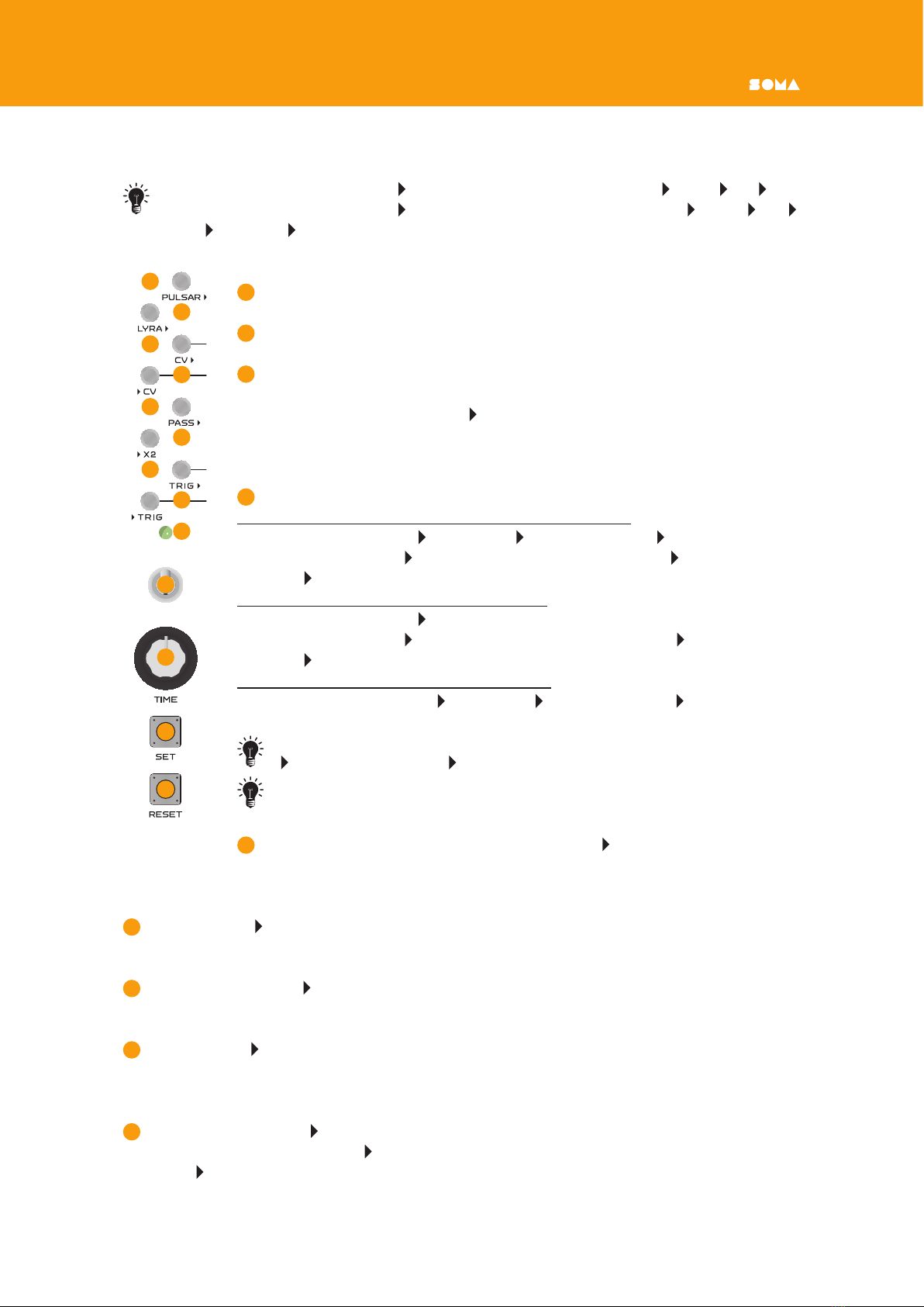
DELAY CELL INTERFACE
All inputs are marked with a before the name of the input ( TRIG, X2, СV).
All outputs are marked with a after the name of the output (TRIG , PASS , CV ,
LYRA , PULSAR )
The interface of each delay cell consists of the following elements:
1RESET button — puts the cell in an inactive state.
2SET button — puts the cell in the active state.
3TIME knob — determines the time during which the cell is in the active
state, which is also the transmission speed of the trigger pulse and the slew
rate of the voltage output CV . When rotating clockwise, the cell activity
time decreases and the transmission speed of the trigger pulse increases.
Slew rate means change of voltage per unit of time.
4Output signal phase toggle switch.
Upper position — normal operation or positive mode.
If the cell is inactive: CV = 0v, LYRA = open, PULSAR = 0v.
If the cell is active: CV = increasing voltage 0–10v, LYRA — closed,
PULSAR — 10v.
Lower position — all outputs are inverted.
If the cell is inactive: CV = 10v, LYRA> = closed, PULSAR> = 10v.
If the cell is active: CV = decreasing voltage 10–0v, LYRA — open,
PULSAR — 0 v .
Middle position — all outputs are disabled.
In any state of the cell: CV = 0v, LYRA = open, PULSAR = 0v.
The position of the switch does not affect the operation mode of the
TRIG input and TRIG output
Actual voltage at the outputs of the cells may slightly vary from the
indicated ones (+\‑ 10%).
5Cell activity indicator. Connected to PULSAR output. With switch 4 in
upper position, a lit indicator indicates an active cell. With switch 4 in lower position, a lit
indicator indicates an inactive cell.
6Input contact TRIG. Connection to the ground of this contact (ornegative pulse) ac‑
tivates the cell.
7Output contact TRIG . At the moment of transition to an inactive state, a short negative
pulse appears at this output.
8Input contact X2. Applying a positive voltage of more than 1 volt to this input doubles
the capacitance of the storage capacitor of the delay line, which is equivalent to multiplying
the TIME parameter by two (doubling the time of activity).
9Output contact PASS . If a new trigger pulse arrives at an already active cell, then it is
transmitted to the output PASS . This passes the given pulse to the next cell connected to
the PASS output, instead of the pulse disappearing.
1
2
3
4
5
6
8
10
12
7
9
11
13
ORNAMENT•8 USER MANUAL
10
Input contact CV. The voltage at this pin controls the TIME pulse rate. Baud rate =
voltage at CV x TIME knob position.
An unconnected pin has a voltage of 3 volts.
11
Output contact CV . With the phase switch in upper position and the cell activated, the
output voltage increases from 0 to 10 volts. With the phase switch in lower position and
the cell activated, the voltage at the contact drops from 10 volts to 0.
This output is designed to control the PULSAR, LYRA and any equipment that can receive
a CV signal from 0 to 10 volts.
12
Output contact LYRA . While the cell is active, this contact is connected to ground. When
the cell is not active, the contact is not connected to anything. With the phase switch in
lower position, the behavior of the contact is inverted.
These outputs are designed to connect the ORNAMENT to the LYRA•8. Use the sensor overlay
adapter (sold separately) to connect to LYRA. Connect LYRA outputs to adapter pins 1–8.
Connect one of the pins of the adapter GND to one of the pins of the GND of ORNAMENT.
In ORNAMENT and adapter both GND contacts are ground. On the adapter, they are con‑
nected to the lower LYRA sensors (bottom row) and the instrument ground. In ORNAMENT,
both GND pins are connected to the ground of the instrument.
The LYRA contact, connected through the adapter to the LYRA, at the moment of acti‑
vation of the cell, connects the sensor to the ground, simulating a nger touching LYRA’s
sensor, and starts this voice of the instrument, thus allowing the ORNAMENT to control
the LYRA.
13
Output contact PULSAR . In an active cell, this contact will have an output voltage of
10 volts. In an inactive cell, the output voltage is 0 volts. With the phase switch in lower
position, the output behavior is inverted.
This output is designed to control the PULSAR and any equipment that can receive a CV
signal from 0 to 10 volts.
HOW PULSE DELAY CELLS WORK
Each of the eight identical cells consists of a capacitor and a circuit that charges and dis‑
charges the capacitor. In the inactive state, the capacitor is discharged, the outputs CV
and PULSAR have a voltage of 0, and the output LYRA is open. In order to activate the
cell, it is necessary to supply a negative trigger pulse to the input TRIG (briefly connect
it to the ground or apply a voltage of less than 2.5 volts). The trigger pulse turns on the
charge circuit of the capacitor and it begins to charge. The charge rate of the capacitor
depends on the input voltage CV and the position of the TIME knob. This relationship can
be expressed by the following formula:
Charge rate = voltage at >CV x position of the TIME knob.
Thus, the higher the input voltage of CV and the closer the position of the TIME knob is
to the maximum, the higher the charge rate of the capacitor. Or, in other words, the pulse
transmission speed is higher and, accordingly, the pulse delay time or cell activity time is
smaller.
In the unconnected state, the input CV has a voltage of 3 volts, and the TIME knob works
referenced to it if nothing is connected to the input.
At the moment when the voltage on the capacitor reaches +10 volts, it instantly discharges
and the cell goes into an inactive state. At the moment of transition to an inactive state, a
short negative pulse is generated at the output TRIG , which can be used to start / activate
any other cell, except for the cell that generated the pulse.
From the point of view of classical circuitry, each cell is a monostable multivibrator or a time

ORNAMENT•8USER MANUAL
relay with a controlled duration of stay in the active state, and some additional functions
which will be described later.
Let’s compare ORNAMENT to a mechanical system in which pulses are transmitted, such
as in billiards. A billiard ball rolls in the free state for a certain amount of time until it hits
another ball, and transfers the pulse to that ball. In ORNAMENT, each cell is like a billiard
ball, and the capacitor charge time is the time of free movement of the ball from the mo‑
ment a pulse was transmitted to it until it encounters the next ball, transmitting the pulse
to it. Looking at the ORNAMENT as a system in which pulses are transmitted with a certain
delay will help to master it faster and more fully, therefore we will return to this analogy in
further explanations.
What if the trigger pulse arrives at an already active cell?
To prevent such a pulse being "wasted in vain" we added an additional output PASS , to
which this pulse is transmitted if the cell is already active. Aside from saving the pulse, this
output also allows you to branch ORNAMENT behavior algorithms by sending pulses to the
TRIG or PASS outputs, depending on whether these cells are active or not.
In order to provide an additional option for discrete control of the cell delay time, we added
an input X2. When a voltage is applied to it of more than 1 volt, it connects an additional
capacitor of the same capacity in parallel with the main capacitor of the cell. Thus, the charge
time and, accordingly, the cell activity and pulse delay times are doubled.
This function has one feature that makes its effect on the operation of the ORNAMENT
more complex: at the time of removing the voltage from X2 and disconnecting the addi‑
tional capacitor from the main capacitor, some voltage may remain on it if the disconnection
occurred during the phase of cell activity. At the time of the next supply of voltage to X2
and the connection of an additional capacitor, the charges of both capacitors will equalize
and will be equal to the sum of their charges divided by two. Thus, the cell activity time may
be less than TIME x 2. We can say that the function X2 remembers the state of the cell at
the last moment of the function’s activity.
The result of the cell activity can be obtained at its three outputs:
CV output — the voltage on it is equal to the voltage on the capacitor and can vary from
0 to 10 volts.
LYRA output — during cell activity is connected to the ground (GND pin).
PULSAR output — in the active state, the output voltage is 10 volts, in the inactive state,
the output is 0 volts.
The phase switch allows you to invert the state of the cell outputs (lower position) or turn
them off completely and make the cell in the musical sense a pause generator (middle position).
The SET button activates the cell, as does a negative pulse at the TRIG input. These but‑
tons are used for bringing the ORNAMENT patch you created into motion. Pressing them
is the equivalent of cue strikes on selected billiard balls in our mechanical model. Thus, by
using the SET buttons, you can add pulses to the ORNAMENT system.
While you hold the SET button, the cell will be active, even if the capacitor is already
fully charged (i.e longer than set by the TIME knob).
The RESET button puts the cell in an inactive state from any phase of activity. Using these
buttons you can reduce the number of pulses in the ORNAMENT system.
ORNAMENT•8 USER MANUAL
PATCHING
Commutation of trigger pulses:
Since the output trigger pulse cannot be transferred back to the input of the same cell,
at least two cells must be connected in order for the pulses to continually circulate. Let’s
examine the principles and techniques of commutation of trigger pulses.
The pulse triggering the cell is a short or long connection of the input TRIG to ground, or
when a voltage of less than 2.5 volts is applied to it. The trigger pulse is negative, meaning
the voltage transition goes from high to low.
TRIG inputs and outputs, as well as the PASS output, are special, since it is through them
that trigger pulses are transmitted and circulate. These inputs and outputs have their own
format and, in principle, are not intended to be connected to anything else or externally.
Of course, with sufcient understanding of their underlying working principles, such con‑
nections are possible. However, for all but the most advanced users, these contacts should
only be connected to each other.
By connecting the TRIG outputs and inputs in various ways, a pulse distribution circuit is
defined.
Multiple TRIG or PASS outputs can be connected to a single input. In this case, the
appearance of a trigger pulse at any of the outputs activates the cell.
One TRIG or PASS output can be connected to several inputs, thus activating seve-
ral cells at once.
LYRA output can also be used as a trigger source. But unlike the TRIG output, it
does not connect to the ground briefly at the moment the cell goes into an inactive
state. Instead, at the moment the cell is activated it remains grounded while the cell
is active (the phase switch can invert this behavior). Thus, the cell connected to it will
be activated in a completely different way.
CV output can also be used as a trigger pulse source. It will remain a trigger source
until the output voltage goes below 2.5 volts.
PULSAR output can also be used as a trigger pulse source. It generates a trigger
until the voltage on PULSAR is 0 volts.
Control of delay/cell activity time:
Inputs CV and X2 are used for time management.
The voltage on CV determines the charge rate of the capacitor; a positive voltage on X2
doubles the capacitance of the capacitor.
ORNAMENT•8USER MANUAL
Consider what commutations for this control are possible:
• CV output of any cell can be connected to input CV of any cell. In this case, the delay
time (capacitor charge time) in the controlled cell will decrease as the control cell moves
from the beginning of its activation to its completion and the voltage at its output CV
will increase.
• PULSAR output of any cell can be connected to the input CV of any cell. In this case,
the delay time / activity of the controlled cell will very much depend on the activity of
the control cell. When the control cell is inactive, the delay time of the controlled cell will
be from 25 seconds to several minutes (depending on the position of the TIME knob).
When the control cell is active, the controlled cell will have a delay time of 50 milliseconds
to 25 seconds (depending on the position of the TIME knob).
• LYRA output of any cell can be connected to the input CV of any cell. In this case,
activation of the control cell will cause an extension of the delay time/activity of the
controlled cell to 25 seconds — 2 minutes (depending on the position of the TIME knob).
This long “freezing” function of individual cells can be used very effectively to create
complex evolving compositions.
• PULSAR or CV outputs of any cell can be connected to input X2 of any cell. Activation
of the control cell will double the delay time / activity of the controlled cell.
• You can combine several outputs together (PULSAR , LYRA , CV ). The resulting voltage
will be the arithmetic average of the voltages at the combined outputs at each point in
time.
• You can connect one output to multiple inputs.
ORNAMENT•8 USER MANUAL
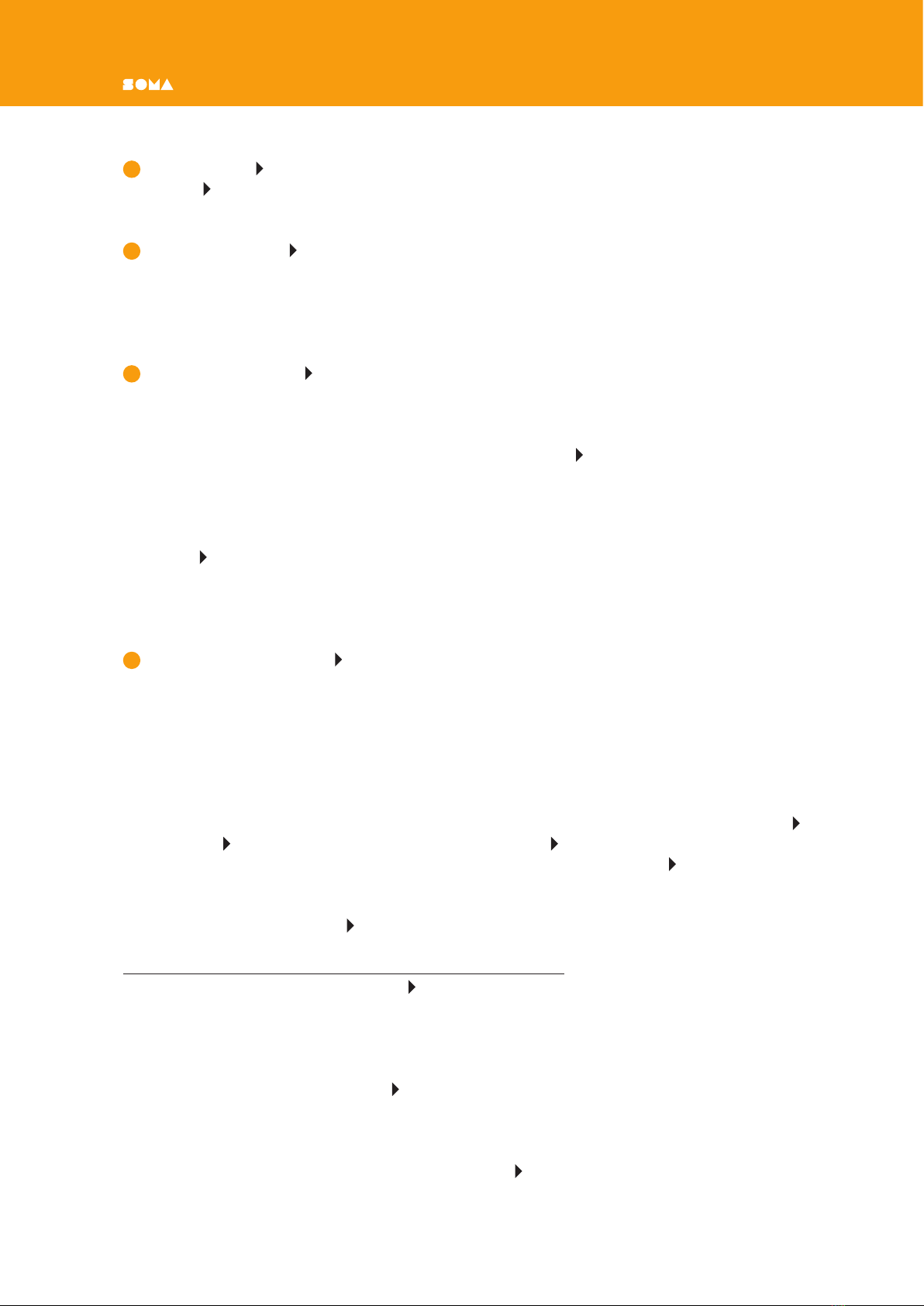
ADDITIONAL BLOCKS AND CONNECTORS
PULSE CONVERTERS
The ORNAMENT contains four identical pulse converters combined with contact‑
minijack adapters. Their purpose is to convert the rectangular output pulses
of the ORNAMENT into short trigger pulses suitable for triggering drum
modules, such as PULSAR or Eurorack.
1Contact input of a rectangular pulse.
2Contact output of the trigger pulse for the drum module.
3 3.5mm minijack connected to pin 2 (adapter in Eurorack format)
In order to connect the ORNAMENT to PULSAR as a drum pattern sequencer, connect the
selected outputs of the PULSAR cells to input pin 1 of the converters, and connect output
pin 2 of the converters to the input TRIG of the PULSAR drum synthesis modules. Connect
one of the GND ORNAMENT pins to the GND PULSAR pin.
Do not forget to always connect the ground of the ORNAMENT with the ground of
the device to which it is connected.
3.5 MM MINIJACK (EURORACK)ADAPTER SOCKETS
Designed to connect a Eurorack system to the ORNAMENT.
Pin 1 is connected to the 3.5 mm minijack 2. The ground of the minijack is
connected to the ORNAMENT ground, therefore it is not necessary to connect
the Eurorack system ground to the GND ORNAMENT pin.
The ORNAMENT has four separate adapters along with four adapters combined with pulse
converters. The adapters combined with pulse converters can also work on their own. If
nothing is connected to input 1 of the pulse converter, its output 2 is in a oating state
and you can use it as an adapter input to a Eurorack system, connecting any outputs and
ORNAMENT inputs that you want to connect to the Eurorack system.
POWER SOCKETS
The ORNAMENT has two power sockets connected in parallel. These can power
LYRA or PULSAR and one or more ORNAMENTs from a single power supply. To do
this, connect the power supply to one of the ORNAMENT sockets, and connect the
power socket of the next device to the second ORNAMENT socket using the supplied power
cord. The ORNAMENT consumes only a small current — from 10 to 50 milliamps, depending
on the operating mode, so any SOMA power supply is capable of simultaneously powering
several ORNAMENTs and one other device.
To power the ORNAMENT, use the included PSU or the PSU from LYRA or PULSAR, or any
stabilized +12 volt power supply, with plus in the center and an output current of at least
100 milliamps.
If several ORNAMENTs or ORNAMENT and another device are connected to a single PSU,
it is no longer necessary to connect the ground of these devices via GND contacts. Ground
will be connected through the power cords.
1
3
2
2
1

ORNAMENT•8USER MANUAL
CONNECTION TO LYRA•8
The ORNAMENT interacts really well with LYRA•8, complementing its organismic synthesis
with no less organizational sequences:) Actually, the ORNAMENT was originally developed
as a sequencer suitable for LYRA, as using a traditional step sequencer for LYRA is unbe‑
coming. But the ORNAMENT greatly exceeded our expectations, so we added the ability to
integrate it both with PULSAR and with any Eurorack systems.
To connect the ORNAMENT to the LYRA, we developed a special adapter-pad (sold separately),
which sits on top of LYRA’s sensors. This allows you to connect external control circuits to
them, while maintaining the ability to play using the sensors by putting your ngers to the
gold‑plated contact pads on the adapter. Connect pins 1–8 of the adapter to the LYRA
ORNAMENT outputs, and the GND pin of the adapter to the GND pin of the ORNAMENT.
You can do it without the adapter if you use suitable clips that can be attached to
LYRA's sensors. In this case, the GND ORNAMENT pin must be connected to any of
the lower LYRA sensors (bottom row).
You can also connect the outputs of the PULSAR and CV of ORNAMENT to the CV inputs
of the LYRA located on the rear panel. To do this, use the 3.5 mm contact-minijack adapters
on ORNAMENT and 3.5 mm jack — 6.3 mm jack cords, or simply connect a crocodile clip to
the pin on the end of the 6.3 mm jack connected to the LYRA.
CONNECTION TO PULSAR•23
The ORNAMENT offers perfect control of the PULSAR, making its rhythmic patterns much
more diverse and allowing you to create elegant generative compositions using only these
two devices.
To trigger drum synthesis modules, use ORNAMENT pulse converters (see the "Pulse Con‑
verter" section) connected to the PULSAR outputs.
You can control various parameters of PULSAR synthesis by connecting the corresponding
PULSAR CV inputs to the CV or PULSAR outputs of ORNAMENT. The LYRA output
can also be used for some inputs, but do not forget that in the active state it is simply
connecting to the ground. Therefore, it will not have any effect until there is some voltage
at the input contact. In the PULSAR, such contacts can be TRIG, inputs of MOD lters, EXT
inputs of synthesis modules, and inputs for controlling the parameters of the FX processor.
Do not forget to always connect the GND of the ORNAMENT with the GND of the PULSAR
and any other device to which it is connected!
You can also control the ORNAMENT by using the various outputs of the PULSAR.
We recommend trying out the outputs of the clock divider, the outputs of the LFO and the
outputs ENV of the envelope generators. The intertwined PULSAR and ORNAMENT are
capable of generating compositions that go beyond understanding.
Vlad Kreimer

ORNAMENT•8 USER MANUAL
MASTERING THE INSTRUMENT
Since ORNAMENT was originally developed for LYRA•8, we will try to show the practical
techniques of patching and playing with the example of ORNAMENT driving LYRA.
Connect each LYRA output to the corresponding metal contact of the LYRA•8 using the
adapter pad (sold separately). Connect the GND ORNAMENT pin to the GND pin of the
adapter so that both devices have a common ground and are ready to communicate. We
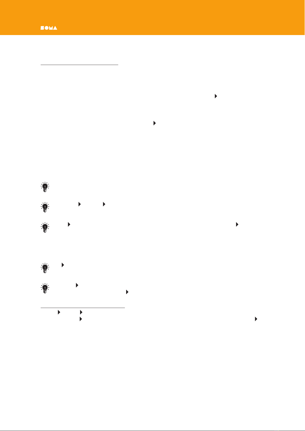
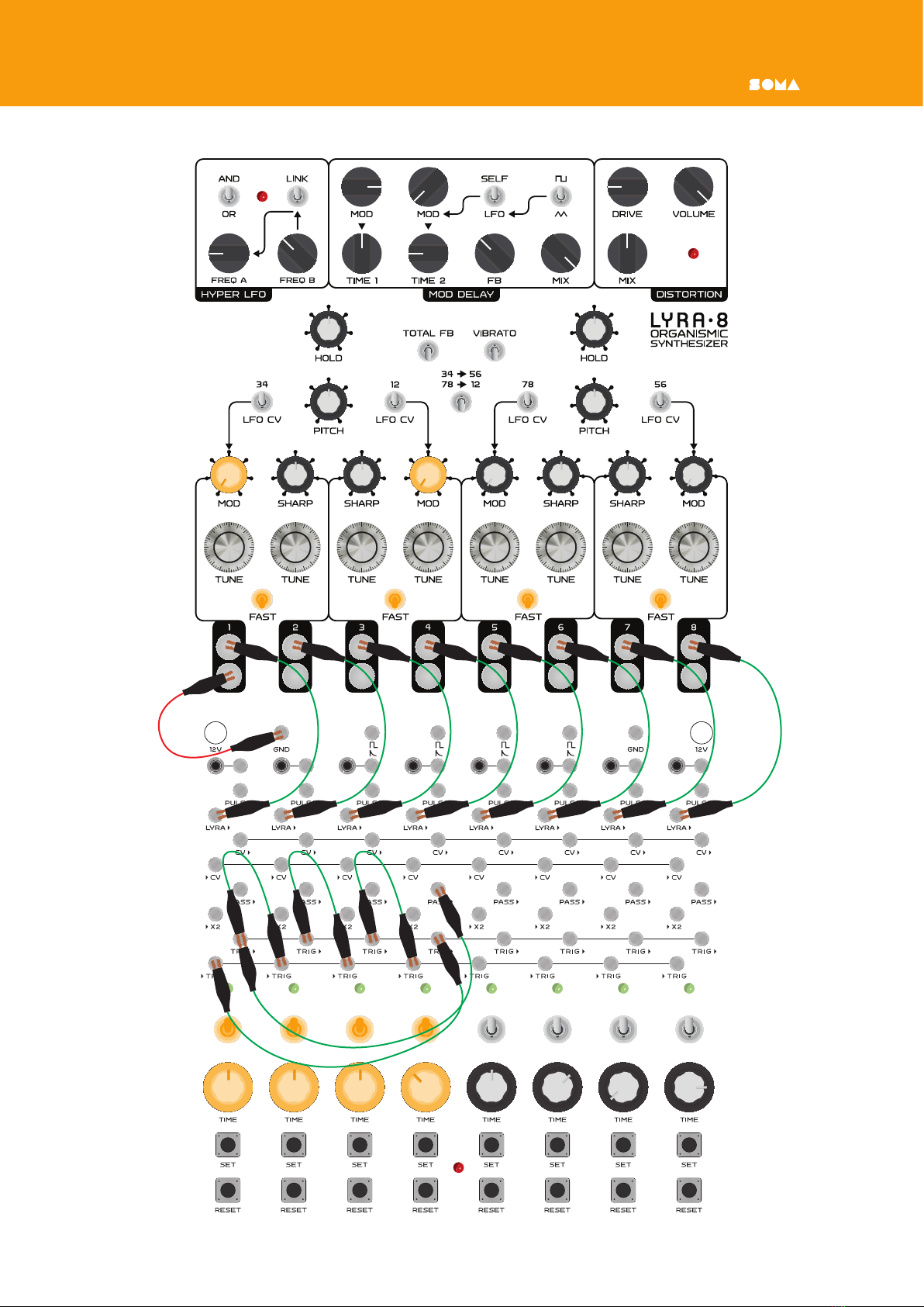
also recommend bringing LYRA and ORNAMENT to the configuration shown in the picture
(everything is turned off except for voices that are in organ mode). Рiс. 1
Now press any SET button. The corresponding voice of LYRA will begin to sound. This
happens because the voltage created at the output of LYRA leads to the triggering of the
corresponding LYRA sensor. The same thing happens when you touch these sensors with
your ngers (orother conductive objects).
The ORNAMENT cell makes LYRA's voice sound for a certain amount of time, which is de‑
termined by the position of the TIME knob. We will say that during this time period this
cell is active, and this period itself will also be called the duration of the cell activity. The
ORNAMENT is able to “hold” LYRA’s voices in a wide range of times — from fractions of a
second to several tens of seconds and even minutes (under certain conditions).
The cell is active while the SET button is pressed, if the duration of the press exceeds the
value set with the TIME knob.
To turn off the active cell before the value set with the TIME knob has elapsed, press the
corresponding RESET button.
A cell can operate in three modes: positive, negative and pause mode. If you ip the phase
toggle switch from a positive (up) to a negative position (down), the ORNAMENT will begin
to “hold” LYRA’s voice indenitely. Pressing SET will cause the ORNAMENT to stop “holding”
LYRA for a while. RESET aborts this action. In negative mode, the cell outputs are inverted.
While the ORNAMENT is “holding” LYRA’s voice, the indicator lights up.
If you put the toggle switch of the cell in the middle position, then the ORNAMENT will no
longer be able to "hold" LYRA under any circumstances. The output state LYRA no longer
changes. However, this does not mean that nothing happens on the other outputs of this
cell or generator.

ORNAMENT•8USER MANUAL
Рiс. 1
ORNAMENT•8 USER MANUAL
PATCHING AND ALLIGATOR CLIPS
Initially, I planned to create a sequencer for LYRA with a small set of predened patches (cell
connections), which “would be enough” for comfortable playing. Eight in a row, two pairs
of four, and so on. But the very rst prototype showed that this approach is not suitable.
LYRA is a polyphonic FM synthesizer, and classical sequencers with a linear loop structure
will not take full advantage of its synthesis capabilities. A sequencer with a non‑linear
structure and very dynamic behavior was needed. As a result, ORNAMENT is a sequencer
that always needs to be patched.
As in PULSAR, ORNAMENT patches are created using special contacts and alligator clips,
which are a great solution and have an excellent price/quality ratio compared to 3.5mm
minijack connectors.
Moreover, the ORNAMENT also has eight 3.5mm minijack adapters for connecting with
Eurorack.
All inputs of ORNAMENT cells or state generators are marked at the beginning, and out‑
puts are marked at the end. I will use the cell number in parentheses to indicate which
cell the contact belongs to. For example, TRIG 1is a trigger input of the rst cell, and
TRIG 6is a trigger output of the sixth cell.
Let's start creating your first patch. This patch is intended to demonstrate the ability of
the ORNAMENT to create complex, lively, unexpected and unpredictable patterns that will
allow LYRA and PULSAR to sound like they’ve never sounded before.
Connect the TRIG 1to the TRIG 2. Put all cells in positive mode by ipping the switches to
the up position. Press and release the SET button on the first cell to activate it. The ORNA‑
MENT will “hold” the first voice during TIME 1. As soon as the rst voice ceases to sound,
the second voice will begin to sound. When the second voice is done, the sound will stop.
This is the simplest cell connection. At that moment, when the rst cell ceases to be active,
the ORNAMENT ceases to “hold” LYRA’s voice, and its output TRIG 1generates a short
trigger pulse. The input of the second cell TRIG 2receives this signal through the con‑
nection that we made, and instantly activates the second cell, and the output LYRA 2of
this cell goes into the “hold” state. At the moment when ORNAMENT “releases” the second
voice, its output TRIG 2also generates a short trigger. But this trigger has no destination.
The ORNAMENT allows you to transfer a trigger from the TRIG output to any cell, with the
exception of the one that generated it. You can pass a trigger with TRIG 2, for example, to
TRIG 1. Then we get a loop of two voices sounding in turn. But for further demonstration,
you need to create a loop of 4 cells. To do this, also connect TRIG 2to TRIG 3, TRIG 3
to TRIG 4, and TRIG 4to TRIG 1. Cell activation signals will not be lost, because each
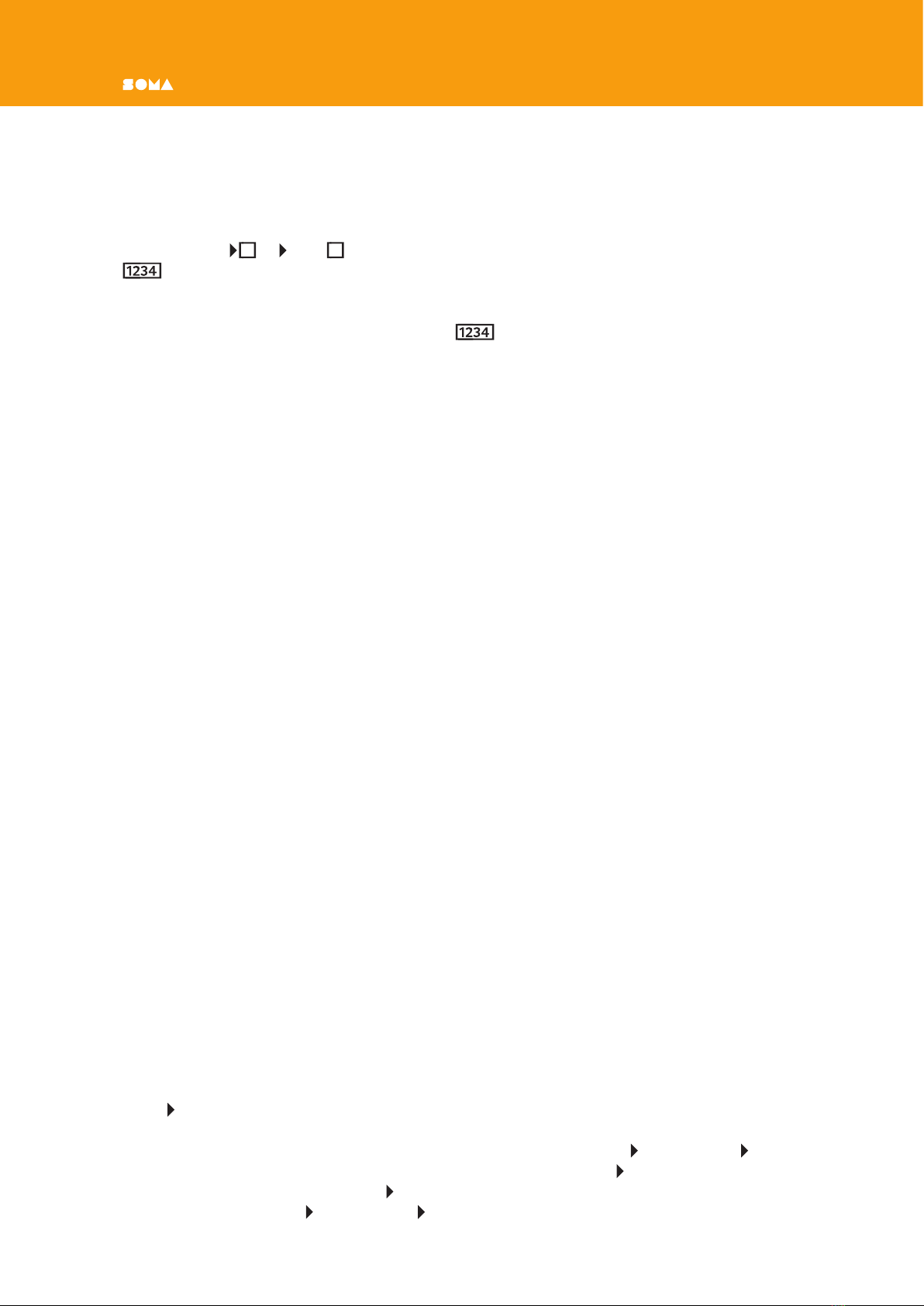
is directed to the corresponding input. I will designate this loop LOOP — the numbers
in rectangles give information about the direction in which the signals go along this loop. In
this case, the direction is 1 2 3 4 1 … In other words, the order of the numbers inside
the rectangles is important.
Press SET on any of the cells from LOOP to start the ORNAMENT. Now it is moving
through LYRA’s voices one by one. Tune them with the TUNE knobs on the LYRA, and use
the TIME knobs to make the duration of the sound of the ORNAMENT cells about equal to
each other. Рiс. 2

ORNAMENT•8USER MANUAL
The ORNAMENT allows you to create loops of any length, with a minimum of 2 steps or cells.
If you need a loop length of, for example, 64 steps, you need to take eight ORNAMENTs and
merge their cells into one chain.
Music is impossible without pauses or rests. Switch any cell from positive mode to pause
mode (middle position of the toggle switch). Now the corresponding LYRA voice will no
longer sound. However, the cell is still involved in the creation of the rhythm, because the
trigger pulses at its inputs and outputs continue to be transmitted. This mode of operation
is useful when you need to turn off some of LYRA’s voices, or in order to use cells for other
purposes. Please note that when this cell is switched to negative mode, the rhythm also
does not change — only the mode of operation of the cell outputs is inverted. Let's return
this cell to positive mode by flipping the switch up again.
TRIG inputs are capable of receiving a signal from any number of TRIG outputs. TRIG
outputs are able to transmit a signal to any number of TRIG inputs.
Using this property, we will complicate LOOP a little, but at the same time we will
immediately go beyond the territory of ordinary linear sequencers. Send a trigger with
TRIG 3not only to TRIG 4, but also to TRIG 5. Press SET of any of the LOOP cells
to start the ORNAMENT. Set the TIME 5value of the fifth cell so that it lasts longer
than the fourth cell. Switch LYRA to the mode so that voices 3 and 4 modulate voices 5 and
6. We will increase the modulation level with the MOD knob 5,6. Now the result of the
FM synthesis between 4 and 5 voices of LYRA is clearly audible, when both of these voices
sound simultaneously.
Experiment with the duration of the fifth cell. If the duration of its sound is about equal to
the sum of the durations of the sound of the rst four cells that formed a loop, this cell will
sound almost constantly. However, if you put cell 5 in a negative mode of operation, then
Рiс. 2

ORNAMENT•8 USER MANUAL
on the contrary it will almost always be silent. Experiment with the duration of the cells, as
well as the mode of their operation, to nd interesting tones at the moments when two or
more LYRA voices sound connected in the FM synthesis mode. Рiс. 3
This principle of creating durations is more like how we create music when we simply play a
musical instrument. We think in lengths of sounds and pauses between them. Later, in order
to effectively interact with other musicians, we are forced to put music on a grid, relative
to which everyone else will be guided.
Pass the trigger by connecting TRIG
5
(put this cell in positive mode) to TRIG
1
to
complicate the patch a bit more (connection TRIG 4— TRIG 1remains). Now the first
cell is activated not only when the fourth cell “releases” LYRA, but also when the fth cell
also “releases” LYRA. You can set the length of the fifth cell so that all the cells will almost
constantly “hold” LYRA. To avoid this, you can put them all in negative mode. The pattern
in the end turned out to be very complicated, but if you change the duration of the rst
and fth cells, the behavior will instantly change. Therefore, ORNAMENT•8 is a synthesizer
of behavior, which only in some special cases can be called a sequencer in the usual sense.
Connecting each of the remaining inputs and outputs increases the functionality and com‑
plexity of the behavior of the ORNAMENT many times, if not exponentially.
Put all used cells in positive mode. Remove the connections TRIG 5— TRIG 1, TRIG 3—
TRIG 5so that only LOOP remains. Set the TIME durations of all cells so that they
are about the same. Start LOOP with one of the SET buttons. Then activate another
cell from LOOP so that two cells are active in the loop at each moment. If the TIME
parameters are equal for all four cells, then three cells, or even all four, can be active in the
loop. But such states will not be stable and soon enough the number of active cells in this
loop will decrease to two.
In a sense, this is the natural mechanism of the ORNAMENT, which does not allow too many
cells in the loop (and therefore too many LYRA voices) to be active at the same time. As
long as the cell is active (and “holds” LYRA), its input TRIG is not susceptible to new trig‑
ger pulses. And if almost all cells are active in the loop, the “eating” or absorption of new
incoming pulses by already active cells is inevitable. The reasons for this lie in the unequal
time of the activity of the cells.
Since the ORNAMENT has a completely analog circuit, the cell durations can be approximately
equal, but they will never be exactly equal. One of the cells will inevitably work longer than
the others by a small margin, and sooner or later it is bound to “eat” an additional pulse
circulating in the system, thereby removing it.
Let’s call such moments "collisions", when our system, as a result of extraordinary events,
by itself radically changes its state.
Linear sequencers avoid collisions, they are simply not possible. There is a main Master Clock
that dictates to everyone when to “go,” and when to “stand.” In the ORNAMENT, each
part is equal. All involved cells participate in the formation of all states at all inputs and
outputs, while living their individual lives, so to speak, in their own independent rhythm. If
you remove or rebuild one of the links, the result will immediately change. Collisions are the
essence of ORNAMENT, which makes it the rst sequencer of its kind.
Hold RESET on any of the LOOP cells to clear the loop by causing all pulses to be
“eaten”. At the moment the RESET button is pressed, the active cell instantly turns off
(stops “holding” LYRA), and a trigger is generated at the TRIG output. If after pressing it,
you continue to hold RESET, then the input TRIG of this cell will be blocked and will not

ORNAMENT•8USER MANUAL
Рiс. 3
ORNAMENT•8 USER MANUAL
be able to receive trigger pulses. The cell will “eat” the trigger pulses until there are none
left, thus clearing the loop after one cycle.
Explore the nature of collisions. Set the durations of the LOOP cells to be approximately
equal to each other. Using the SET buttons, simultaneously (asmuch as possible) activate
the rst and third cells. An active pair of cells starts to “move” in the loop: 1 and 3, 2 and
4. Note that from the point of view of ORNAMENT (more precisely, from the point of view
of trigger pulses on TRIG and TRIG ), two parallel state transfer processes occur: 1 2 3
4 1 … and 3 4 1 2 3 … And from the point of view of LYRA’s voices, it might seem
that the transfer processes are different: 1 2 1 … and 3 4 3 … Which is equivalent to
two independent loops of ORNAMENT.
Increase the duration of one cell from LOOP . In a few loop cycles, the pair will cease
to exist. The “fast” cell at the moment of switching off will try to transfer the trigger to the
blocked input of the “slow” cell at the moment when it is active. As a result, only one active
cell will remain in the loop. There is no way to avoid this process. Each time after the SET
button is pressed, the “slow” cell will very quickly absorb the “fast” cells.
It’s possible to calculate approximately the number of cycles for which a collision occurs in
a given loop. Let’s say that cells 1 and 3 are started simultaneously in LOOP . We also
assume that the durations of the first three are the same and equal to TIME 1, and the
duration of the fourth exceeds the duration of the others by dT (difference in time), which
is slightly less than TIME 1 (aslight difference). In this case, on each cycle, the fourth cell
will be late with dT turned off for this time. And the second active cell in this loop will “catch
up” with it a little. In order to completely “catch up” with it and try to pass the trigger, it
needs to overcome the time TIME 1. For each cycle, it overcomes dT. So the collision will
happen through TIME 1 /dT cycles. You can understand this in practice simply by observing
the ORNAMENT.
This situation will be repeated always when the cell durations are at least slightly different.
As a result, there will be only one active cell in the loop. But cell durations create the rhythm
of our pattern — therefore, we should be able to make them different without losing poly-
phony. Intuition provided me with a solution to this problem — a trigger that hits a blocked
input should not be wasted. The user‑specified polyphony must be retained. This is how
the PASS output came to be.
Set the durations of the LOOP cells equal to each other.Double the length of the fourth
cell compared to the rest. Use the SET buttons to start two cells simultaneously. Make sure
that very soon only one cell remains active. Connect the output PASS 4to the input TRIG 1.
Run a pair of cells in LOOP . Now, every time the third cell sends a trigger pulse to
TRIG 4 while it is active, the signal skips through PASS 4and activates the first cell. As
a result, polyphony of 2 voices is preserved in the loop. Рiс. 4
However, when the fourth cell tries to transfer the trigger to the rst while it is active, we
again lose the second “voice” of the polyphony, because the output PASS 1is not connected
to anything. And such a collision will surely happen sooner or later.You can connect PASS 1
to TRIG 2to continue to struggle with asynchrony in this loop. But then you have to
connect PASS 2, and so on...
There is a much better solution. Connect PASS 1to TRIG 5. Switch the fifth cell into the
positive mode of operation and make its duration noticeably shorter than the duration of
cells 1,2,3. Use the SET buttons to start two cells in LOOP . Now you need to wait until
the trigger from the output PASS 1 jumps to the input of the fth cell, which will begin
ORNAMENT•8USER MANUAL
Рiс. 4
ORNAMENT•8 USER MANUAL
to “hold” LYRA’s fifth voice. How often this trigger will skip depends on the TIME value of
the fourth cell. Moreover, this connection is nonlinear. Note that when a trigger arrives at
the input of the fth cell, only one cell is active in loop 1-4. Let's return polyphony to this
loop, but with a delay.
Connect TRIG 5to TRIG 3. Make the fifth cell duration very long compared to the LOOP
cycle. Thus, polyphony will return to the loop, but after a certain time, which is deter‑
mined by the duration of the fth cell. If you put the fth cell in pause mode, then we will
not hear LYRA’s voice. But at the same time, the fth cell will act as a temporary storage of
the trigger pulse of the second active LOOP cell. Рiс. 5
Behind all these collisions and “running around” cells, one should not forget that ORNA‑
MENT is a tool that provides additional opportunities for playing LYRA•8. Now you can
create some kind of behavior on the ORNAMENT that triggers the LYRA•8 and focus all
your attention on changing the sound of LYRA. While the ORNAMENT is playing the LYRA,
you can smoothly change the pitch of its voices, vary the modulation value, and change the
FM synthesis algorithm.
The ORNAMENT also provides additional opportunities for controlling the presence of each
voice in the nal sound. If a voice is too annoying or is currently out of tune, you can simply
switch the ORNAMENT cell corresponding to that voice to pause mode. The rhythmic pattern
will not change, but this voice will cease to be audible. There are situations when LYRA’s
voice takes up more space than you would like, but you don’t want to turn it off completely
— you just want to reduce its presence. Simply switch the cell corresponding to this voice to
the negative mode. Now all periods of sound will turn into pauses, and pauses will sound
instead. The rhythmic pattern will not change in terms of the ORNAMENT cells and the
interaction of its trigger outputs and inputs. But the resulting sound of LYRA will change
signicantly. For additional changes, you can switch several cells at once to negative mode.
The patch that we created is the most basic and simply demonstrates the operation of some
inputs and outputs. Your task now is to learn how to create your own patches. Make the
cells begin to communicate with each other. For example, make it so that two loops, not
connected to each other, exchange rare events and create new soundscapes.
Once I created a patch in which there was one loop of four cells. With the help of additional
cells that were in pause mode, I made the polyphony in this loop smoothly change. First, one
voice, then there were two, then three, then again two, then one. The cycle was repeated
in 1 minute.
I am sure that we are just beginning to study the unique capabilities of systems such as
ORNAMENT. This is a one of a kind musical instrument. And you also need to learn to play
it. But in this case, the playing means creation and modication of patches that generate
the composition in a very unusual way for the human mind.
The remaining inputs and outputs of the ORNAMENT can create and receive control signals.
These signals can, for example, change cell durations directly during operation. This is an
example of the “butterfly effect” within the ORNAMENT — nothing will go unnoticed.
Input X2. If a positive voltage is applied to this cell input (more than 1 volt), then the time
corresponding to the TIME parameter of this cell will double.
Positive voltage in the ORNAMENT can be obtained in two ways: CV and PULSAR . When
the cell is active, “holds” LYRA and its indicator is lit, then PULSAR has a high voltage level
of +10 volts. The voltage at the CV output at this moment rises from 0 volts to 10. When
the cell is not active, CV and PULSAR are low.
Table of contents
Popular Recording Equipment manuals by other brands


Northern Airborne Technology
Northern Airborne Technology AA224 series Installation and operation manual

PAC
PAC RSIC-SI-CRC EZ installation guide

Campbell
Campbell SC105 CS instruction manual

Adeunis RF
Adeunis RF sigfox MODBUS MASTER ARF8240CA user guide

TerraTec
TerraTec GRABSTER AV 400MX manual

sound4
sound4 IMPACT Maintenance and operation instruction manual


