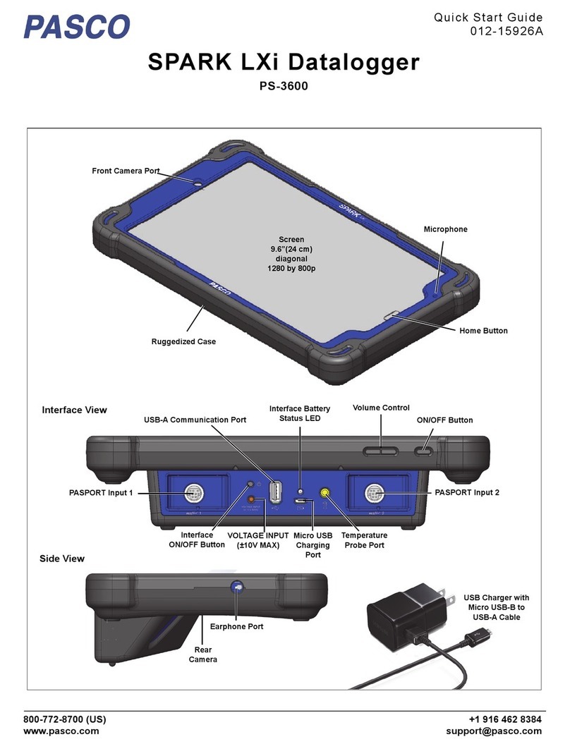
Somat eDAQlite User manual

User Manual
EnglishDeutschEspanol
I2773-4.4en HBM: public
Somat eDAQ
lite
with TCE Software

Somat eDAQ
lite
2
I2773-4.4en
HBM: public

I2773-4.4en
3
Somat eDAQ
lite
Contents Page
Safety Information 13
1 Getting Started 17
1.1 Overview 17
1.1.1 eDAQ
lite
Layers 17
1.2 Equipment 17
1.2.1 Provided Equipment 17
1.2.2 Support Equipment 18
1.3 Setting Up the System 19
1.3.1 Installing Somat Test Control Environment (TCE) 19
1.3.2 Getting Familiar with the eDAQ
lite
System 19
1.3.3 Setting Up the eDAQ
lite
20
1.4 Test Process 21
2 Using the eDAQ
lite
23
2.1 eDAQ
lite
Base System 23
2.1.1 Status LEDs 23
2.1.2 eDAQ
lite
Layers 24
2.1.3 Updating Firmware 27
2.2 Communications 28
2.2.1 Communications Methods 28
2.2.2 Changing the eDAQ
lite
IP Address and Host Name 29
2.3 Power Considerations 30
2.3.1 Input Power Voltage 31
2.3.2 Battery Power 32
2.3.3 Remote Power 32
2.3.4 Power Save Mode 33
2.3.5 Powering an eDAQ
lite
from a Vehicle 34
HBM: public

Somat eDAQ
lite
4
I2773-4.4en
2.4 Data Storage 37
2.4.1 Data Formats 37
2.4.2 Data Storage Options 38
2.5 Networking eDAQ
lite
/eDAQ Systems 39
2.5.1 Hardwired Network 39
2.5.2 Wireless Network 40
3 Test Control Environment (TCE) 41
3.1 TCE User Interface 41
3.1.1 Setup Windows 41
3.1.2 Pull Down Menus 44
3.1.3 Toolbar 48
3.1.4 Status Bar 49
3.2 TCE Preferences 49
3.2.1 Communications 50
3.2.2 General 50
3.2.3 FCS Specific 52
3.2.4 Remote Test Run Control 54
3.2.5 Scope and Spectrum Display 56
3.2.6 Run-Time Display 56
3.2.7 Group DVM Display 57
3.2.8 Auto Range Options 57
4 Using TCE 59
4.1 Defining a Test 59
4.1.1 Adding a Network Node 59
4.1.2 Configuring the Hardware 60
4.1.3 Creating Channels and DataModes™ 61
4.1.4 Using Existing Setup Definitions 62
HBM: public

I2773-4.4en
5
Somat eDAQ
lite
4.2 Calibrating Input Channels 63
4.2.1 Calibration Modes 63
4.2.2 Calibration Control 67
4.2.3 Calibration Specifications 68
4.3 Running a Test 68
4.3.1 Initializing a Test 69
4.3.2 Prerun Options 69
4.3.3 Previewing a Test Run 70
4.3.4 Starting a Test Run 70
4.3.5 Using Interactive Triggers 71
4.3.6 Stopping a Test Run 71
4.3.7 Ending a Test 71
4.4 Monitoring Test Status 71
4.5 Viewing Channel Displays 72
4.5.1 Displays Overview 73
4.5.2 Common Display Options 74
4.5.3 DVM 75
4.5.4 Scope Plot 77
4.5.5 Spectrum Plot 78
4.5.6 Digital Readout 79
4.5.7 Bar Chart 80
4.5.8 Strip Chart 81
4.6 Uploading Test Data 82
4.6.1 Uploading SIE Data Files 82
4.6.2 Uploading SIF Data Files 82
4.6.3 Extracting Data from SIE or SIF Files 83
4.7 Using Remote Control Operation 85
HBM: public

Somat eDAQ
lite
6
I2773-4.4en
4.8 Networking eDAQ
lite
/eDAQ Systems 86
4.8.1 Using Remote Control with a Network 87
5eDAQ
lite
Hardware 89
5.1 ELCPU (Base Processor) 89
5.1.1 ELCPU Available Inputs 89
5.1.2 ELCPU Configuration Options 89
5.2 ELCOM (Vehicle Network Communications Layer) 91
5.2.1 ELCOM Available Inputs 91
5.2.2 ELCOM Configuration Options 91
5.3 ELDIO (Digital Input/Output Layer) 91
5.3.1 ELDIO Available Inputs and Outputs 91
5.3.2 ELDIO Configuration Options 92
5.4 ELBRG (Bridge Layer) 94
5.5 ELHLS (High Level Analog Layer) 95
5.6 ELNTB (Non-Isolated Thermocouple Layer) 95
5.7 EGPS-5HZ (Somat GPS Receiver) 96
5.7.1 Available Inputs 97
5.7.2 Configuration Options 97
5.8 EGPS-200 (Precision GPS Module) 97
5.8.1 Available Inputs 98
5.8.2 Configuration Options 98
5.9 Vehicle Bus Module 99
5.9.1 VBM Available Inputs 99
5.9.2 VBM Configuration Options 99
5.9.3 Importing A2L Files 100
5.10 SMART Modules 101
5.11 Network Camera Devices 102
HBM: public
HBM: public

I2773-4.4en
7
Somat eDAQ
lite
5.11.1 Network Camera Available Inputs 102
5.11.2 Network Camera Configuration 102
5.11.3 Network Camera Troubleshooting 105
6 Input Channels 107
6.1 Common Input Channel Parameters 107
6.1.1 Desired Measurement 107
6.1.2 Output Sample Rate 108
6.1.3 Full-Scale Values 108
6.1.4 Output Data Type 108
6.1.5 Calibration Table 108
6.1.6 Prerun Rezero 109
6.1.7 Display Control 110
6.2 Digital Input Channels 110
6.2.1 Digital Input 110
6.2.2 Pulse Counter 111
6.3 Analog Input Channels 113
6.3.1 Bridge 113
6.3.2 Simultaneous High Level 116
6.4 SMART Module Input Channels 118
6.4.1 SMSTRB4 (Strain SMART Module) 118
6.4.2 SMITC (Thermocouple SMART Module) 121
6.5 Temperature Input Channels 121
6.5.1 Thermocouple 121
6.6 Bus-Oriented Input Channels 121
6.6.1 Common Bus Channel Parameters 122
6.6.2 Vehicle Bus Message Channel 123
6.7 Network Camera Input Channel 124
HBM: public

Somat eDAQ
lite
8
I2773-4.4en
6.8 Simulation Input Channels 125
6.8.1 Simulation File 125
6.8.2 Simulation Function Generator 126
6.8.3 Simulation Message 127
7 Computed Channels 129
7.1 Common Computed Channel Parameters 129
7.2 Arithmetic Computed Channels 130
7.2.1 Desk Calculator 130
7.2.2 Engineering Scaler 133
7.2.3 Integer Scaler 133
7.2.4 Integrator 134
7.2.5 Pulse Counter 136
7.2.6 Directional Velocity 137
7.2.7 State Mapper 138
7.2.8 Statistical Analysis 139
7.2.9 Damage Equivalent Load 141
7.2.10 Fatigue Damage 142
7.3 Triggering Computed Channels 145
7.3.1 Interactive Trigger 145
7.3.2 Trigger Generator 145
7.3.3 Timed Trigger 146
7.3.4 Triggered Zero Suppression 147
7.3.5 Bitmap Trigger 148
7.3.6 Test Run Stopper 149
7.3.7 Power Saver 149
7.4 Time, Sample Rate and Filter Computed Channels 150
7.4.1 Time Channel 150
HBM: public

I2773-4.4en
9
Somat eDAQ
lite
7.4.2 Time Base Shifter 151
7.4.3 Down Sampler 151
7.4.4 Up Sampler 152
7.4.5 Smoothing Filter 153
7.4.6 Digital Filter 154
7.5 Tracking Computed Channels 155
7.5.1 Max Track 155
7.5.2 Min Track 155
7.5.3 Range Track 156
7.5.4 Anomaly Detect 157
7.5.5 Triggered Latch 158
7.5.7 Valid Data Gate 160
8 DataModes™ 161
8.1 DataMode™ Memory Consumption 161
8.2 Common DataMode™ Parameters 161
8.3 Sequential DataModes™ 163
8.3.1 Time History 163
8.3.2 Burst History 164
8.3.3 Event Slice 167
8.3.4 Message Logger 168
8.3.5 Peak Valley 168
8.3.6 Peak Valley Slice 169
8.4 Histogram DataModes™ 170
8.4.1 Common Histogram Parameters 170
8.4.2 Peak Valley Matrix 171
8.4.3 Rainflow 171
8.4.4 Time at Level (One Dimensional) 172
HBM: public
7.5.6 Over Range Detector 159

Somat eDAQ
lite
10
I2773-4.4en
8.4.5 Time at Level (Multidimensional) 172
8.5 Digital Output 173
9eDAQ
lite
Web Interface 175
9.1 Main Page 175
9.2 System Tab 175
9.2.1 System Setup 176
9.2.2 System Status 177
9.2.3 System Maintenance 177
9.3 Hardware Tab 178
9.3.1 Hardware Table 178
9.3.2 Manage Network Cameras 179
9.3.3 Select Storage Device 180
9.4 Channels Tab 180
9.5 Test Tab 180
9.6 Data Tab 181
9.6.1 SIE Test Data 181
9.6.2 SIF Test Data 182
9.7 Custom Tab 182
9.8 Help Tab 182
10 Troubleshooting 183
10.1 Troubleshooting Procedure 183
10.2 Known Problems 184
10.3 eDAQ
lite
Flags 184
10.3.1 Status Flags 184
10.3.2 Error Flags 186
10.4 Corrupt SIF File Data Recovery 187
10.5 Tips on Eliminating eDAQ
lite
OverFlow Errors 188
HBM: public

I2773-4.4 en
11
Somat eDAQ
lite
11 Data Types 191
12 Cable Pinouts 195
12.1 ELCPU (Main Processor) 195
12.1.1 Communications Cable 195
12.1.2 Power Cable 197
12.2 ELCOM (Vehicle Communications Layer) 197
12.3 ELHLS (High Level Analog Layer) 198
12.4 ELBRG (Bridge Layer) 198
12.5 ELDIO (Digital I/O Layer) 199
12.6 Vehicle Bus Modules (VBM) 199
12.6.1 Transducer Cable for VPW Interface 199
12.6.2 Transducer Cable for J1708 Interface 200
12.6.3 Transducer Cable for CAN/SWC Interface 200
12.6.4 Transducer Cable for ISO9141/KW2000 Interface 201
12.6.5 Transducer Cable for MIL1553 Interface 201
13 Device Wiring 203
13.1 ELDIO (Digital I/O Layer) 203
13.1.1 ELDIO Digital Input 203
13.1.2 ELDIO Digital Output 204
13.2 ELHLS (High Level Analog Layer) 205
13.2.1 ELHLS Analog Input 205
13.2.2 SMSTRB4 (Strain SMART Module) 205
13.3 ELBRG (Bridge Layer) 206
13.3.1 ELBRG Bridge Transducers 206
13.3.2 ELBRG Analog Input 208
14 Data Synchronization 209
14.1 Data Synchronization Characterization Method 209
HBM: public

Somat eDAQ
lite
12
I2773-4.4en
14.2 Analog Channel Synchronization 209
14.2.1 ELHLS and ELBRG Channel Synchronization 210
14.3 Digital Channel Synchronization 211
14.4 Resampled Channel Synchronization 211
14.4.1 Bus-Oriented Channel Synchronization 212
14.4.2 Thermocouple Channel Synchronization 212
14.5 Networked eDAQ
lite
/eDAQ System Synchronization 212
14.5.1 Hardwired Network Synchronization 212
14.5.2 Wireless Network Synchronization 212
15 Digital Filtering 213
15.1 Signal Aliasing 213
15.2 Digital Filter Characteristics 213
15.2.1 ELHLS and ELBRG Digital Filters 214
16 Xth-Percentile Benchmark Tests 219
17 Data Processing Algorithms 221
17.1 Peak Valley Processing Algorithm 221
17.2 Rainflow Cycle Counting Algorithm 221
18 Cable Resistances 223
19 CE Compliance 225
19.1 eDAQ
lite
Hardware 225
19.2 Cables 226
HBM: public

I2773-4.4en
13
Somat eDAQ
lite
Safety Information
Safety Rules
The supply connection, as well as the signal and sense leads, must be installed in
such a way that electromagnetic interference does not adversely affect device
functionality.
Automation equipment and devices must be covered over in such a way that adequate
protection or locking against unintentional actuation is provided (such as access
checks, password protection, etc.).
When devices are working in a network, these networks must be designed in such a
way that malfunctions in individual nodes can be detected and shut down.
Safety precautions must be taken both in terms of hardware and software, so that a
line break or other interruptions to signal transmission, such as via the bus interfaces,
do not cause undefined states or loss of data in the automation device.
Before connecting the device, make sure that the mains voltage and current type
specified on the type plate correspond to the mains voltage and current type at the site
of installation and that the current circuit used is sufficiently safe.
The maximum permissible supply voltage for the eDAQ
lite
is 18 V DC for the ELCPU
processor and 55 V DC for the ELCPU-PLUS processor.
Appropriate use
The eDAQ
lite
and its connected transducers may be used for measurement tasks
only and directly related control tasks. To ensure safe operation, the transducer may
only be used as specified in the operating manual. It is also essential to follow the
respective legal and safety regulations for the application concerned during use. The
same applies to the use of accessories.
Each time, before starting up the equipment, you must first run a project planning and
risk analysis that takes into account all the safety aspects of automation technology.
This particularly concerns personal and machine protection.
Additional safety precautions must be taken in plants where malfunctions could cause
major damage, loss of data or even personal injury. In the event of a fault, these
precautions establish safe operating conditions.
This can be done, for example, by mechanical interlocking, error signaling, limit value
switches, etc.
General dangers of failing to follow the safety instructions
The eDAQ
lite
complies with the state of the art and is safe to operate. Inappropriate
use and operation by untrained personnel can give rise to remaining dangers.
Anyone responsible for installing, starting up, maintaining or repairing the equipment
needs to have read and understood the operating manual and in particular the safety
instructions.
Maintenance and cleaning
The eDAQ
lite
is maintenance free. Please note the following when cleaning the
housing:
•
Before cleaning, disconnect the equipment from the power supply.
•
Clean the housing with a soft, slightly damp (not wet!) cloth. Never use solvents,
since these could damage the labelling on the front panel and the display.
HBM: public
HBM: public

Somat eDAQ
lite
14
I2773-4.4en
•
When cleaning, ensure that no liquid gets into the equipment or connections.
Remaining dangers
The scope of supply and performance of the data acquisition system covers only a
small area of measurement technology. In addition, equipment planners, installers and
operators should plan, implement and respond to the safety engineering
considerations of measurement technology in such a way as to minimize remaining
dangers. Prevailing regulations must be complied with at all times. There must be
reference to the remaining dangers connected with measurement technology. After
making settings and carrying out activities that are password-protected, you must
make sure that any controls that may be connected remain in safe condition until the
switching performance of the amplifier system has been tested.
In this manual, the following symbols are used to point out remaining dangers:
DANGER
Meaning: Maximum danger level
Warns of an imminently dangerous situation in which failure to comply with safety
requirements will result in death or serious bodily injury.
WARNING
Meaning: Dangerous situation
Warns of a potentially dangerous situation in which failure to comply with safety
requirements can result in death or serious bodily injury.
CAUTION
Meaning: Potentially dangerous situation
Warns of a potentially dangerous situation in which failure to comply with safety
requirements could result in death or serious bodily injury.
Meaning: Electrostatic sensitive devices
Devices marked with this symbol can be destroyed by electrostatic discharge. Please
observe the precautions for handling electrostatic sensitive devices.
Symbols pointing out notes on use and waste disposal as well as useful information:
NOTE
Points out that important information about the product or its handling is being given.
Meaning: CE mark
The CE mark enables the manufacture to guarantee that the product complies with the
requirements of the relevant CE directives (the declaration of conformity is available at
http://www.hbm.com/HBMdoc).
HBM: public

I2773-4.4en
15
Somat eDAQ
lite
Meaning: Statutory marking requirements for waste disposal
National and local regulations regarding the protection of the environment and
recycling of raw materials require old equipment to be separated from regular
domestic waste for disposal.
For more detailed information on disposal, please contact local authorities or the
dealer from whom you purchased the product.
Working safely
Error messages may only be acknowledged if the cause for the error has been
removed and no further danger exists.
Conversions and modifications
HBM’s express consent is required for modifications affecting the Somat eDAQ
lite
design and safety. HBM does not take responsibility for damage resulting from
unauthorized modifications.
In particular, any repair or soldering work on motherboards is prohibited. When
exchanging complete assemblies, it is essential to use original HBM parts only.
The product is delivered from the factory with a fixed hardware and software
configuration. Changes can only be made within the possibilities documented in the
manuals.
Qualified personnel
The equipment may be used by qualified personnel only; the specifications and the
special safety regulations need to be followed in all cases.
This means people who meet at least one of the three following requirements:
•
Knowledge of the safety concepts of automation technology is a requirement
and as project personnel, you must be familiar with these concepts.
•
As automation plant operating personnel, you have been instructed how to
handle the machinery and are familiar with the operation of the equipment and
technologies described in this documentation.
•
As commissioning engineers or service engineers, you have successfully
completed the training to qualify you to repair the automation systems. You are
also authorized to activate, to ground and label circuits and equipment in
accordance with safety engineering standards.
It is also essential to comply with the appropriate legal and safety regulations for the
application concerned during use. The same applies to the use of accessories.
The term “qualified personnel” refers to staff familiar with the installation, fitting,
start-up and operation of the product, and trained according to their job.
HBM: public

Somat eDAQ
lite
16
I2773-4.4en
HBM: public

I2773-4.4en
17
Somat eDAQ
lite
1 Getting Started
1.1 Overview
The Somat eDAQ
lite
is a sealed, stand-alone, microprocessor-based data acquisition
system designed for portable data collection in the harshest of environments. It has
leading-edge signal conditioning and a capacity to perform a broad range of on-board
data processing. Engineered to be rugged and mobile, the eDAQ
lite
is tested to
military standards at 10 g’s from 55 to 2000 Hz. Internal back-up batteries protect the
eDAQ
lite
from unplanned power losses or low voltage events. Hundreds of
synchronous channels are possible in a single system with virtually limitless channel
counts when networking multiple systems using Ethernet communications.
1.1.1 eDAQ
lite
Layers
The eDAQ
lite
consists of one base processor layer and a number of optional add-on
layers. The following table lists the available layers, including the base processor.
1.2 Equipment
This section describes the provided equipment and the support equipment necessary
to set up the eDAQ
lite
system and run a test.
1.2.1 Provided Equipment
The initial shipment of a basic eDAQ
lite
contains the hardware listed below; additional
hardware may be included based on options ordered. The eDAQ
lite
also comes with
Somat Test Control Environment (TCE) software.
NOTE
If any items do not arrive as expected, contact your system supplier, nearest HBM
sales representative or HBM immediately.
Name Order Number Description
ELCPU 1-ELCPU-2 eDAQ
lite
Base Processor
1-ELCPU-PLUS-2 eDAQ
lite
Base Processor with Extended Voltage
ELCOM 1-ELCOM-2 eDAQ
lite
Vehicle Network Communications Layer
ELHLS 1-ELHLS-2 eDAQ
lite
High Level Analog Layer
ELBRG 1-ELBRG-350-2 eDAQ
lite
Bridge Layer; 350-Ohm
1-ELBRG-120-2 eDAQ
lite
Bridge Layer; 120-Ohm
ELDIO 1-ELDIO-B-2 eDAQ
lite
Digital Input/Output Layer
1-ELDIO-5HZGPS-2 eDAQ
lite
Digital Input/Output Layer with GPS
ELNTB 1-ELNTB-2 eDAQ
lite
Non-Isolated Thermocouple Layer
ELBAT 1-ELBAT-2 eDAQ
lite
Battery Layer
HBM: public

Somat eDAQ
lite
18
I2773-4.4en
1.2.2 Support Equipment
In addition to the eDAQ
lite
base processor, add-on layers and included cables, set up
of the eDAQ
lite
system requires an adequate power supply, a support PC and any
transducers or sensors needed for testing.
Power Supply
The eDAQ
lite
is designed to always be connected to an adequate power supply for
the duration of all test runs. An example of an adequate power supply is a charged
nominal 12-volt vehicle battery system that reliably supplies around 13.5 volts.
Additionally, an optional Somat AC Power Supply (1-E-AC-2 or 1-E-AC/18-2) is
available.
NOTE
HBM also offers the Somat ELBAT eDAQ
lite
Battery Layer (1-ELBAT-2-2) that can
support an eDAQ
lite
for over 10 hours depending on the system configuration.
For more information on eDAQ
lite
power, see “Power Considerations” on page 30.
Support PC
A support PC is necessary to run TCE. The PC must meet these minimum
requirements for TCE to operate correctly.
•
Microsoft Windows® 95/98/NT/2000/XP/Vista/7
•
40 MB of available hard disk space
•
CD-ROM drive or Internet access (required for updating and installing software)
•
16 MB of RAM (32 MB recommended)
•
Mouse or other pointing device
•
An Ethernet card
Sensors
The eDAQ
lite
supports a wide variety of sensors for data acquisition, including
several offered directly by HBM. Contact your sales representative or visit
www.hbm.com/somat for more information.
Item (Order No.) Description
Somat eDAQ
lite
Somat eDAQ
lite
base layer and any optional layers.
Somat Communications
Cable
(1-SAC-ESR9/XO-2 or
1-SAC-ESR9/HUB-2)
26-pin HDD-Sub male plug with two connector cables, one
labeled “E-ETHERNET” which ends in an RJ-45 connector
and the other labeled “RS232” which ends in a 9-pin D-Sub
female plug. The XO cable is used for connection directly to
the host computer, while the optional HUB cable is used for
network operation.
Somat Power Cable
(1-SAC-EPWR15-2)
15-pin D-Sub female plug with two connector cables ending in
pigtails.
Somat TCE Installation CD CD containing the installation files for TCE.
HBM: public

I2773-4.4en
19
Somat eDAQ
lite
1.3 Setting Up the System
Setting up the eDAQ
lite
data acquisition system involves installing TCE on the
support PC and setting up the eDAQ
lite
hardware.
1.3.1 Installing Somat Test Control Environment (TCE)
To install TCE:
1. Run the TCE installer found on the TCE/eDAQ
lite
distribution CD or downloaded
from the www.hbm.com/somat. Follow the instructions on screen.
2. When prompted, enter the desired destination folder for the installation. By default,
the TCE installation program places each new software release in a unique folder.
3. If updating to a new version of TCE, copy or move the file “TceMS.ini” from the
working directory of the previous TCE installation folder to the working directory of
the new TCE installation folder. This process transfers the current TCE preference
settings into the new version of TCE.
Notes on the Installation and Working Directories
•
Using a Common Installation Folder: Previous versions of the TCE installer used a common destination folder for all
releases. To continue using a common folder, uninstall the previous TCE version before starting the new installation.
Change the installation program default folder name to the common folder name (previously, “C:\Program
Files\Somat\Tce_eDAQ”) during the installation process. To keep TCE preference settings, be sure to save the
“TceMS.ini” file before uninstalling the previous version of TCE.
•
Default Working Directory: Effective starting with TCE 3.15, the TCE working directory now defaults to a subfolder in
the “Documents” or “My Documents” directory named “Somat\TCE vX.XX.X build XXX”. This working directory
includes all database files and the TCE preferences files. New user database files must be added to this working
directory.
•
Modifying the Working Directory: To change the working directory, open the TCE application shortcut properties by right
clicking the application shortcut or the entry in the Windows Start menu and select Properties. In the Target field, delete
the second string, which starts with
“-d
, leaving only
“C:\Program Files\Somat\TCE vX.XX.X build
XXX\TceMs.exe”
. Then type the desired working directory in the Start In field. Note that the folder must already exist.
For Windows XP or earlier, the Start In folder can reside in Program Files. Select Apply to save the new settings.
1.3.2 Getting Familiar with the eDAQ
lite
System
eDAQ
lite
Front Panel
All of the connectors, the power switch and the status LEDs needed to set up the
eDAQ
lite
are on the ELCPU front panel as shown in the following diagram.
HBM: public

Somat eDAQ
lite
20
I2773-4.4en
Figure 1-1:
Diagram of the eDAQ
lite
front panel.
Somat Communications Cables
The eDAQ
lite
is compatible with several different communications cables. Each cable
has a 26-pin D-Sub for connection to the eDAQ
lite
Comm port. The cables may also
have an Ethernet X/O connector for direct communication from the eDAQ
lite
to the
PC, an Ethernet HUB connector for communication through an Ethernet hub, a 9-pin
serial connector for communications through a PC serial port or a set of two LEMO
sync connectors for networking eDAQ/eDAQ
lite
systems. A summary of the available
communication cables is below.
1.3.3 Setting Up the eDAQ
lite
To power the eDAQ
lite
and establish communications with its support PC:
1. Connect the 26-pin D-Sub connector of a Somat Communications Cable to the
Comm connector on the eDAQ
lite
. For Ethernet communication, connect the
RJ-45 connector either directly to the PC or to an Ethernet hub, depending on the
communications table. For serial communication, connect the 9-pin D-Sub
connector directly to the PC. The serial connection may be removed once the setup
process is complete, but it may be helpful in network setup should difficulties arise
with Ethernet communication.
2. Connect the appropriate cable(s) to the eDAQ
lite
for the desired type of
transducers or sensors.
3. Make sure the power supply for the eDAQ
lite
is turned off and connect the Somat
Power Cable (1-SAC-EPWR15-2) between the eDAQ
lite
Power connector and the
power supply. Use the red and black pigtails on the cable labeled “POWER” for the
main power connection: black to the negative or ground terminal and red to the
Communications Cable
Ethernet
(X/O)
Ethernet
(HUB) Serial Sync
1-E-ETHERNET X/O-2 X
1-E-ETHERNET HUB-2 X
1-SAC-ESR9/XO-2 X X
1-SAC-ESR9/HUB-2 X X
1-SAC-ESYNCADAPT-2 X X
1-SAC-ESYNCADAPT-SC-2 X X X
%QOO 2QYGT
*55
2QYGT5YKVEJ
5VCVWU.'&U2KP&5WD
%QOOWPKECVKQPU
%QPPGEVQT
2KP&5WD
2QYGT%QPPGEVQT
*55%QPPGEVQTHQTG&+52.#
HBM: public
Table of contents
