Somex MAX 40 COM Technical manual

Dossier technique d‘origine
Technical Document
Translations of the «Dossier technique d‘origine»
DE
FR
GB
Betriebsanleitung
Übersetzung des «Dossier technique d‘origine»
MAX 40 COM

2. Commissioning
2.1 Assembly instructions
2.2 Connecting the power to the
machine
2.3 Rating data
2.4 Operating convditions
2.5 Safety instructions to be ob-
served on commissioning
2.6 Taking the machine into ser-
vice
3. Handling / Operation
3.1 Machine
3.2 Tools
4. Service / Maintenance
4.1 Preventive maintenance
4.2 Maintenance and wearing
parts
4.3 Speed option
4.4 Repair
4.5 Warranty
4.6 Storage
4.7 Disposal / Environmental com-
patibility
4.8 Assistance
1. Notes on safety
1.1 General notes on safety
1.2 Use of the machine for pur-
poses for which it is intended
1.3 Incorrect use
1.4 Declaration of incorporation
1.5 Symbol legend
1.6 Abbreviations
2. Inbetriebnahme
2.1 Montageanleitung
2.2 Anschliessen der Maschine
2.3 Leistungsdaten
2.4 Betriebsbedingungen
2.5 Sicherheitshinweise zur Inbe-
triebnahme
2.6 Inbetriebnahme
3. Handhabung / Betrieb
3.1 Maschine
3.2 Werkzeuge
4. Instandhaltung / Wartung
4.1 Vorbeugende Instandhaltung
4.2 Wartungs- und Verschleissteile
4.3 Drehzahlvarianten
4.4 Reparatur
4.5 Garantieleistung
4.6 Lagerung
4.7 Entsorgung / Umweltverträg-
lichkeit
4.8 Unterstützung
1. Sicherheitshinweise
1.1 Allgemeine sicherheitstech-
nische Hinweise
1.2 Bestimmungsgemässe Ver-
wendung
1.3 Nicht bestimmungsgemässe
Verwendung
1.4 Einbauerklärung
1.5 Symbolerklärung
1.6 Abkürzungsverzeichnis
3. Utilisation / Exploitation
3.1 Machine
3.2 Outillages
2. Mise en service
2.1 Instructions de montage
2.2 Raccordement de la machine
2.3 Performances
2.4 Conditions d‘exploitation
2.5 Indications relatives à la sécu-
rité lors de la mise en service
2.6 Mise en service
4. Maintenance / Entretien
4.1 Maintenance préventive
4.2 Pièces de maintenance et
d’usure
4.3 Variation des vitesses
4.4 Réparation
4.5 Prestations de garantie
4.6 Entreposage
4.7 Elimination / Compatibilité
environnementale
4.8 Assistance
1. Indications rélative à la
sécurité
1.1 Instructions générales de
sécurité
1.2 Utilisation conforme à la desti-
nation
1.3 Utilisation contraire à la desti-
nation
1.4 Déclaration d‘incorporation
(Original)
1.5 Glossaire des symboles
1.6 Glossaire des abréviations
2
Table des matières
Inhaltsverzeichnis
Contents
Table des matières
Inhaltsverzeichnis
Contents
Table des matières
Inhaltsverzeichnis
Contents
Table des matières
Inhaltsverzeichnis
Contents
DEFR GB

MAX 40 :
Spindle
MAX 40 MQL :
Spindle
+ Coolant through the tool
MAX 40 COM :
Broche basique
+ Clamping system
+ Authorization spindle rotation
sensor
MAX 40 COD :
Spindle
+ Clamping system
+ Authorization spindle rotation
sensor
+ Gripper position sensor
+ Top 0 sensor
MAX 40 COD MQL :
Spindle
+ Clamping system
+ Authorization spindle rotation
sensor
+ Gripper position sensor
+ Top 0 sensor
+ Coolant through the tool
MAX 40 COC :
Spindle
+ Clamping system
+ Authorization spindle rotation
sensor
+ Gripper position sensor
+ Top 0 sensor
+ Absorber system
MAX 40 COC MQL :
Spindle
+ Clamping system
+ Authorization spindle rotation
sensor
+ Gripper position sensor
+ Top 0 sensor
+ Absorber system
+ Coolant through the tool
MAX 40 :
Spindel
MAX 40 IK :
Spindel
+ Kühlmittelzufuhr
MAX 40 COM :
Spindel
+ Werkzeugspannsystem
+ Freigabe einer Spindelumdrehung
MAX 40 COD :
Spindel
+ Werkzeugspannsystem
+ Freigabe einer Spindelumdrehung
sensor
+ Position der Spannzange sensor
+ Top 0 sensor
MAX 40 COD IK :
Spindel
+ Werkzeugspannsystem
+ Freigabe einer Spindelumdrehung
sensor
+ Position der Spannzange sensor
+ Top 0 sensor
+ Kühlmittelzufuhr
MAX 40 COC :
Spindel
+ Werkzeugspannsystem
+ Freigabe einer Spindelumdrehung
sensor
+ Position der Spannzange sensor
+ Top 0 sensor
+ Absorbersystem
MAX 40 COC IK :
Spindel
+ Werkzeugspannsystem
+ Freigabe einer Spindelumdrehung
sensor
+ Position der Spannzange sensor
+ Top 0 sensor
+ Absorbersystem
+ Kühlmittelzufuhr
MAX 40 :
Broche
MAX 40 ARC :
Broche
+ arrosage par le centre
MAX 40 COM :
Broche
+ serreur
+ capteur autorisation rotation
broche
MAX 40 COD :
Broche
+ serreur
+ capteur autorisation rotation
broche
+ capteur de position de la pince
+ capteur Top 0
MAX 40 COD ARC :
Broche
+ serreur
+ capteur autorisation rotation
broche
+ capteur de position de la pince
+ capteur Top 0
+ arrosage par le centre
MAX 40 COC :
Broche
+ serreur
+ capteur autorisation rotation
broche
+ capteur de position de la pince
+ capteur Top 0
+ système de compensation d‘effort
MAX 40 COC ARC :
Broche
+ serreur
+ capteur autorisation rotation
broche
+ capteur de position de la pince
+ capteur Top 0
+ système de compensation d‘effort
+ arrosage par le centre
Table des matières
Inhaltsverzeichnis
Contents
3
Table des matières
Inhaltsverzeichnis
Contents
Table des matières
Inhaltsverzeichnis
Contents
Table des matières
Inhaltsverzeichnis
Contents
DEFR GB

1.1 General notes on
safety
This operation manual is appli-
cable for the machine MAX40
COM
The machine may be handle ex-
clusively by personnel who are
qualified.
1.2 Use of the machine for
purposes for which it
is intended
This machine with slide, ac-
cessories, and equipment is
specifically ideal for plant con-
struction. It is also suitable for all
machining operations requiring
an axial force and a torque.
1.3 Incorrect use
All users other than those de-
scribed under section 1.2 are
regarded as incorrect use and
are therefore not admissible.
1.4 Declaration of incorpo-
ration
The manufacturer SOMEX
S.A.S., Z.A. de la Passerelle,
F-68190 Ensisheim, hereby de-
clares for the partly completed
machinery (see reverse side
for type and serial no.) that the
following fundamental require-
1.1 Allgemeine sicher-
heitstechnische Hin-
weise
Diese Betriebsanleitung gilt für
die Maschine MAX40 COM
Nur qualifiziertes Personal darf
die Maschine handhaben.
1.2 Bestimmungsgemässe
Verwendung
Die Maschine mit Schlitten, Zu-
behör und Ausrüstung ist spezi-
ell geeignet für den Anlagenbau.
Sie ist ebenfalls geeignet für alle
Bearbeitungsoperationen die
eine axiale Kraft und ein Dreh-
moment benötigen.
1.3 Nicht bestimmungsge-
mässe Verwendung
Alle andern als unter Pkt. 1.2
beschriebenen Verwendungen
gelten als nicht bestimmungs-
gemässe Verwendung und sind
deshalb nicht zulässig.
1.4 Einbauerklärung (Ori-
ginal)
Hiermit erklärt der Hersteller
SOMEX S.A.S., Z.A. de la Pas-
serelle, F-68190 Ensisheim, der
unvollständigen Maschine (Typ
und Serien-Nr. siehe Rückseite)
dass folgende grundlegenden
Anforderungen der Richtlinie
1.1 Indications générales
de sécurité
Ce dossier technique est vala-
ble pour la machine MAX40.
COM
Seul le personnel qualifié peut
opérer sur la machine.
1.2 Utilisation conforme à
la destination
La machine avec chariot, ac-
cessoires et équipements est
spécialement conçue pour la
construction d’installations. Elle
convient également à toutes
les opérations d’usinage qui
nécessitent une force axiale et
un couple.
1.3 Utilisation contraire à
la destination
Toutes les applications autres
que celles décrites au point
1.2 sont à considérer comme
contraires à la destination et ne
sont donc pas admissibles.
1.4 Déclaration
d‘incorporation
Par la présente, le fabricant
SOMEX S.A.S., Z.A. de la Pas-
serelle, F-68190 Ensisheim, de
la quasi-machine (voir au dos le
type et le numéro de série) dé-
clare que les exigences essen-
tielles suivantes de la directive
4. Maintenance / Entretien
4. Instandhaltung / Wartung
4. Service / Maintenance
3. Utilisation / Exploitation
3. Handhabung / Betrieb
3. Handling / Operation
2. Mise en service
2. Inbetriebnahme
2. Commissioning
4
DE GB
FR
1. Ind. relative à la sécurité
1. Sicherheitshinweis
1. Notes on safety

ments of the Directive 2006/42/
EC are applied and fulfilled in
accordance with Annex I: 1.1.2,
1.1.3, 1.1.5, 1.2.1, 1.2.2, 1.3.7,
1.3.8.1, 1.5.1, 1.5.4, and 1.6.1.
Technical documentation was
generated for the partly com-
pleted machinery in accordance
with Annex VII of the Machinery
Directive. Document Agent: P.
Peter. Authorised sites are pro-
vided with this technical docu-
mentation in paper or electronic
form on justified request. This
partly completed machinery
may be put into operation only
when the machine in which the
partly completed machinery is
to be incorporated has been as-
certained to fulfil the conditions
under the Machinery Directive.
F-Ensisheim,
P. Pe te r
Managing Director
1.5 Symbol legend
Attention!
Make sure to read!
This information is very impor-
tant for ensuring correct opera-
tion of the product. Failure to ob-
serve this information can result
in a defect.
Note on safety / Hazard
This information serves to
achieve safe operation. Fail-
ure to observe this information
may compromise the operator‘s
safety.
2006/42/EG nach Anhang I zur
Anwendung kommen und ein-
gehalten werden: 1.1.2, 1.1.3,
1.1.5, 1.2.1, 1.2.2, 1.3.7, 1.3.8.1,
1.5.1, 1.5.4 und 1.6.1. Für die
unvollständige Maschine wurde
eine technische Dokumenta-
tion nach Anhang VII der Ma-
schinenrichtlinie erstellt. Doku-
mentbevollmächtigter: P. Peter.
Autorisierten Stellen wird auf
begründetem Verlangen die
technischen Dokumentationen
in Papier- oder elektronischer
Form zur Verfügung gestellt.
Diese unvollständige Maschine
darf nur dann in Betrieb genom-
men werden, wenn festgestellt
wurde, dass die Maschine, in
welche die unvollständige Ma-
schine eingebaut werden soll,
den Bestimmungen der Maschi-
nenrichtlinie entspricht.
F-Ensisheim,
P. Pe te r
Geschäftsleiter
1.5 Symbolerklärung
Achtung!
Unbedingt lesen!
Diese Information ist sehr wich-
tig für die Funktionsgewährlei-
stung des Produktes. Bei Nicht-
beachten kann ein Defekt die
Folge sein.
Sicherheitshinweis / Gefahr
Diese Information dient zum
Erlangen eines sicheren Be-
triebes. Bei Nichtbeachten ist
die Sicherheit für den Bediener
nicht gewährleistet.
2006/42/CE sont appliquées
et respectées selon l‘annexe I
: 1.1.2, 1.1.3, 1.1.5, 1.2.1, 1.2.2,
1.3.7, 1.3.8.1, 1.5.1, 1.5.4 et
1.6.1. Une documentation tech-
nique conforme à l‘annexe VII
de la directive Machines a été
conçue pour la quasi-machine.
Fondé de pouvoir : P. Peter. Les
documents techniques seront
communiqués aux organismes
autorisés sur demande motivée
sous forme papier ou électro-
nique. Cette quasi-machine ne
peut être mise en service que
s‘il est constaté que la machine
à laquelle la quasi-machine
doit être incorporée répond
aux dispositions de la directive
Machines.
F-Ensisheim,
P. Pe te r
Directeur
1.5 Glossaire des sym-
boles
Attention !
A lire impérativement!
Cette information est très impor-
tante pour la garantie de fonc-
tionnement du produit. La non
observation peut entraîner une
défectuosité.
Indication relative à la sécurité /
Danger
Cette information sert à per-
mettre une utilisation sûre. En
cas de non observation, la sé-
curité de l’utilisateur n’est pas
garantie.
5
1. Ind. relative à la sécurité
1. Sicherheitshinweis
1. Notes on safety
2. Mise en service
2. Inbetriebnahme
2. Commissioning
3. Utilisation / Exploitation
3. Handhabung / Betrieb
3. Handling / Operation
4. Maintenance / Entretien
4. Instandhaltung / Wartung
4. Service / Maintenance
DEFR GB
1. Ind. relative à la sécurité
1. Sicherheitshinweis
1. Notes on safety
Information
This information serrves for a
good understanding of the op-
eration of the product, thereby
permitting full exploitation of
the operational potential of the
product.
Technical Document
Read the technical document
prior to commissioning.
Safety glasses and ear protec-
tion.
Wear safety glasses and ear
protection.
Disposal
Friendly-to-the-environment dis
Power connector
Before any work is carried out
on the machine, disconnect the
power connector.
1.6 Abbreviations
MAX40: Registered trademark
ISO: International Organization
for Standartization
HSK: Short tool chucking holder
AC/DC Alternating/Direct current
BN: Color brown
BU: Color blue
BK: Color black
Information
Diese Information dient zum
guten Verständnis der Funktion
des Produktes. Dadurch lässt
sich die volle Leistungsfähigkeit
des Produktes ausschöpfen.
Betriebsanleitung
Vor Inbetriebnahme des Pro-
duktes Betriebsanleitung lesen.
Schutzbrille und Gehörschutz
Schutzbrille und Gehörschutz
tragen.
Entsorgung
Umweltfreundliche Entsorgung.
Netzstecker
Vor jedem Arbeiten an der Ma-
schine Netzstecker ziehen.
1.6 Abkürzungsverzeich-
nis
MAX40: Codierter Produktname
ISO: Internationale Organisation
für Normung
HSK: Hohlschaftkegel
AC/DC: Wechsel-/Gleichstrom
BN: Farbe braun
BU: Farbe blau
BK: Farbe schwarz
Information
Cette information sert à la com-
préhension du fonctionnement
du produit. Par cela, la pleine
capacité de fonctionnement du
produit pourra être exploitée.
Dossier technique
Lire le dossier technique avant
la mise en service.
Lunettes de protection et pro-
tection de l’ouille.
Porter des lunettes de protec-
tion et une protection de l’ouille.
Elimination
Elimination favorable à l’environ-
nement.
Fiche du secteur
Avant tout travail sur la machine,
retirer la fiche du secteur.
1.6 Glossaire des abrévia-
tions
MAX40: Nom codé du produit
ISO: International Standard Orga-
nisation
HSK: Porte outil à cône court
AC/DC: Courant alternatif et continu
BN: Couleur brune
BU: Couleur bleue
BK: Couleur noir
4. Maintenance / Entretien
4. Instandhaltung / Wartung
4. Service / Maintenance
3. Utilisation / Exploitation
3. Handhabung / Betrieb
3. Handling / Operation
2. Mise en service
2. Inbetriebnahme
2. Commissioning
6
DE GB
FR
1. Ind. relative à la sécurité
1. Sicherheitshinweis
1. Notes on safety

2.1 Assembly instructions
Maximum admissible machine
fastening error.
The machine is fastened at the
bores provided in the housing.
Screws of quality grad 8.8 must
be used. The starting torque for
the holding down bolt is maxi-
mum 30Nm.
Connect the cables only after
the machine has been com-
pletely installed.
2.1 Montageanleitung
Max. zulässige Abweichung für
die Befestigung der Maschine.
Die Befestigung der Maschine
erfolgt mit den im Gehäuse vor-
gesehenen Bohrungen.
Schrauben der Güteklasse 8.8
müssen verwendet werden. Das
Anzugsmoment für die Befesti-
gungsschrauben beträgt maxi-
mal 30Nm.
Anschluss der Kabel erst nach
vollständiger Montage der Ma-
schine.
2.1 Instructions de monta-
ge
Déviation maximale admissible
pour la fixation de la machine.
La fixation de la machine est
réalisée à l‘aide des trous pré-
vus dans le corps de l‘appareil.
Utiliser des vis de la classe de
qualité 8.8. Le couple initial de
serrage pour les vis de fixation
est en maximum 30Nm.
Raccordement des câbles uni-
quement après le montage
complet de la machine.
7
1. Ind. relative à la sécurité
1. Sicherheitshinweis
1. Notes on safety
2. Mise en service
2. Inbetriebnahme
2. Commissioning
3. Utilisation / Exploitation
3. Handhabung / Betrieb
3. Handling / Operation
4. Maintenance / Entretien
4. Instandhaltung / Wartung
4. Service / Maintenance
DEFR GB
2. Mise en service
2. Inbetriebnahme
2. Commissioning

2.1.1 Outline dimensions draw2.1.1 Massbild2.1.1 Croquis des dimension
1. Ind. relative à la sécurité
1. Sicherheitshinweis
1. Notes on safety
4. Maintenance / Entretien
4. Instandhaltung / Wartung
4. Service / Maintenance
3. Utilisation / Exploitation
3. Handhabung / Betrieb
3. Handling / Operation
2. Mise en service
2. Inbetriebnahme
2. Commissioning
8
DE GB
FR
1. Ind. relative à la sécurité
1. Sicherheitshinweis
1. Notes on safety
4. Maintenance / Entretien
4. Instandhaltung / Wartung
4. Service / Maintenance
3. Utilisation / Exploitation
3. Handhabung / Betrieb
3. Handling / Operation
2. Mise en service
2. Inbetriebnahme
2. Commissioning

9
1. Ind. relative à la sécurité
1. Sicherheitshinweis
1. Notes on safety
2. Mise en service
2. Inbetriebnahme
2. Commissioning
3. Utilisation / Exploitation
3. Handhabung / Betrieb
3. Handling / Operation
4. Maintenance / Entretien
4. Instandhaltung / Wartung
4. Service / Maintenance
DEFR GB
2. Mise en service
2. Inbetriebnahme
2. Commissioning
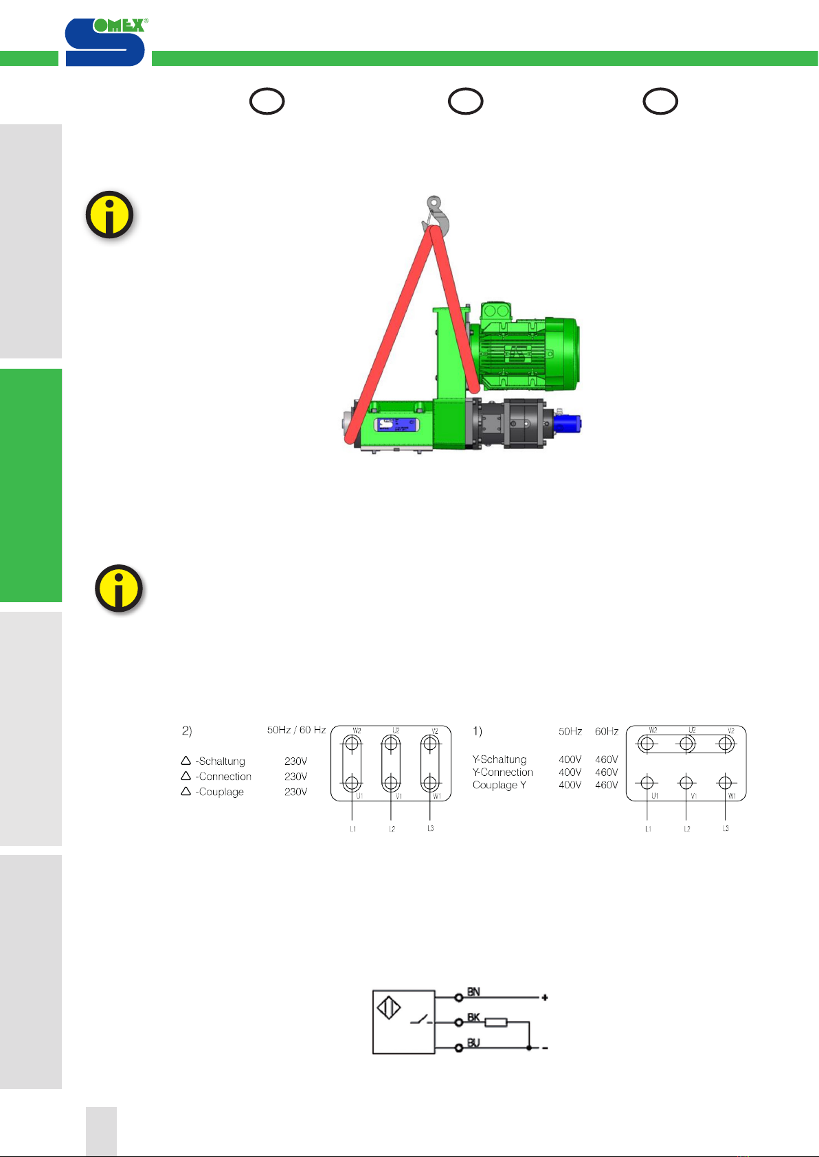
2.1.2 Fastening of the machine
on its mount
Correct lifting of machine with a
crane.
2.2 Connecting the power
to the machine
Motor power:
400/230V; 50Hz
460/230V; 60Hz
1) 400/460V connection
2) 230/260V connection
Inductive proximity switch pow-
er:
10...30V
2.1.2 Befestigung der Maschi-
ne auf einem Träger
Richtiges Heben der Maschine z.B.
mit Kran.
2.2 Anschliessen der Ma-
schine
Motor-Speisung:
400/230V; 50Hz
460/230V; 60Hz
1) Anschluss 400/460V
2) Anschluss 230V
Versorgung der induktiven Nä-
herungsschalter:
10...30V
2.1.2 Fixation de la machine
sur son support
Manutention correcte de la machine
p. ex. avec une grue.
2.2 Raccordement de la
machine
Alimentation du moteur :
400/230V; 50Hz
460/230V; 60Hz
1) Branchement 400/460V
2) Branchement 230V
Alimentation des détecteurs
inductif :
10...30V
1. Ind. relative à la sécurité
1. Sicherheitshinweis
1. Notes on safety
4. Maintenance / Entretien
4. Instandhaltung / Wartung
4. Service / Maintenance
3. Utilisation / Exploitation
3. Handhabung / Betrieb
3. Handling / Operation
2. Mise en service
2. Inbetriebnahme
2. Commissioning
10
DE GB
FR
1. Ind. relative à la sécurité
1. Sicherheitshinweis
1. Notes on safety
4. Maintenance / Entretien
4. Instandhaltung / Wartung
4. Service / Maintenance
3. Utilisation / Exploitation
3. Handhabung / Betrieb
3. Handling / Operation
2. Mise en service
2. Inbetriebnahme
2. Commissioning

2.3 Rating data
2.4 Operating convditions
The machine must be protect-
ed against direct spray and/or
pressurized cutting fluids.
2.5 Safety instructions to
be observed on com-
missioning
The unit must be taken into
service by specialized person-
nel who are instructed on the
requirements of the valid safety
standards.
Always conduct test runs with-
out workpieces.
Use the attachments intended
for each application. Do not trim
attachments for applications
they have not been designed
for.
Check the sense of rotation be-
fore starting the machine.
2.3 Leistungsdaten
2.4 Betriebsbedingungen
La machine doit être protégée
des projections directes et/ou
sous pression de liquide de
coupe.
2.5 Sicherheitshinweise
zur Inbetriebnahme
Die Inbetriebnahme muss durch
eine fachkundige Person durch-
geführt werden, welche mit den
Sicherheitsvorschriften vertraut
ist.
Kontrollläufe immer ohne Werk-
stück fahren.
Verwenden Sie die zweckent-
sprechenden Werkzeuge; trim-
men Sie kein Werkzeug für eine
Anwendung, für die es nicht vor-
gesehen ist.
Vor Inbetriebnahme Drehrich-
tung prüfen.
2.3 Performances
2.4 Conditions d‘exploita-
tion
Die Maschine muss vor di-
rektem Spritz- und Kühlwasser
geschützt werden.
2.5 Indications relatives à
la sécurité lors de la
mise en service
La mise en service doit être
effectuée par une personne
compétente et formée aux exi-
gences des normes de sécurité
en vigneur.
Les contrôles doivent toujours
être effectués sans pièce à usi-
ner.
Utilisez les outils adaptés au
but recherché ; ne modifiez pas
d’outils en vue d’une application
pour laquelle ils ne sont pas
prévus.
Contrôler le sens de rotation
avant la mise en service.
Capacité de perçage max. Max. Bohrleistung Max. drilling capacity Ø35 / 600N /mm2
Couple transmissible max. Max. übertragbares Drehmoment Max. transmissible torque 400 Nm
Vitesse de rotation (roulements
contact oblique) Drehzahlbereich (Schrägkugel-
lager) Speed range (angular contact
bearings) 9 000 min-1
Tolérance de concentricité Rundlaufgenauigkeit Concentricity 0,01 mm
Moteur standard ISO, IP55 Standard ISO Motor, IP55 Standard ISO motor, IP55 1,1 - 5,5 kW
Tension moteur 50/60Hz Normalspannung 50/60Hz Standard voltage at 50/60Hz 230 - 460 V
Broche standard Standardspindel Standard spindle ISO40 / HSK63
Norme porte outil ISO40 Norm für Werkzeughalter ISO40 Norm for tool holder ISO40 ISO 7388
DIN 69871
Norme tirette type A pour porte
outil ISO40 Norm für Anzugsbolzen vom Typ A
für Werkzeughalter ISO40 Norm for pull studs according type
A for tool holder ISO40 ISO 7388/11
DIN 69872
Pression pneumatique du vérin de
désserrage du porte outil Pneumatischer Druck der Winde
entspannung Werkzeughalter Pneumatic pressure of the unclam-
ping jack of tool holder 5 - 10 bars
Effort de serrage du porte outil Anzugskraft auf den Werkeughalter Clamping force of the tool holder 10 kN
Joint tournant Drehdurchführung Rotating Union Deublin
Poids / Couleur Gewicht / Farbe Weight / Colour 75 kg / RAL 6018
Plage de températures en
exploitation Temperaturbereich Betrieb Temperature range during
operation 5-50°C
Humidité de l‘air relative maxi. Max. relative Luftfeuchtigkeit Maximum relative air humidity 90% at +30 °C
65% at +50 °C
Alimentation du moteur Motorspeisung Motor power 230 - 460 V
50 - 60 Hz
Alimentation des détecteurs Schalterspeisung Sensor power 10...30 DC
11
1. Ind. relative à la sécurité
1. Sicherheitshinweis
1. Notes on safety
2. Mise en service
2. Inbetriebnahme
2. Commissioning
3. Utilisation / Exploitation
3. Handhabung / Betrieb
3. Handling / Operation
4. Maintenance / Entretien
4. Instandhaltung / Wartung
4. Service / Maintenance
DEFR GB
2. Mise en service
2. Inbetriebnahme
2. Commissioning
2.6 Taking the machine
into service
2.6.1 Settings
2.6.1.1 Authorization of spindle
rotation
This sensor indicates if the pis-
ton of the jack is in „back“ posi-
tion and authorizes the putting
in rotation of the spindle.
Never put in rotation the spindle
that this sensor is in the state „1“.
2.6 Inbetriebnahme
2.6.1 Einstellung
2.6.1.1 Freigabe einer Spindelu-
mdrehung
Dieser Sensor zeigt an, ob der
Druckzylinder sich in der „hin-
teren“ Position befindet und
wenn das der Fall ist, gestattet
daraufhin, dass die Spindel sich
drehen kann.
Die Spindel soll nie drehen,
ohne dass dieser Sensor sich
im Zustand „1“ befindet.
2.6 Mise en service
2.6.1 Réglages
2.6.1.1 Autorisation rotation
broche
Ce capteur indique si le piston
du vérin est en position « arrière
» et autorise la mise en rotation
de la broche.
Ne jamais mettre en rotation la
broche sans que ce capteur soit
à l‘état « 1 ».
1. Ind. relative à la sécurité
1. Sicherheitshinweis
1. Notes on safety
4. Maintenance / Entretien
4. Instandhaltung / Wartung
4. Service / Maintenance
3. Utilisation / Exploitation
3. Handhabung / Betrieb
3. Handling / Operation
2. Mise en service
2. Inbetriebnahme
2. Commissioning
12
DE GB
FR
1. Ind. relative à la sécurité
1. Sicherheitshinweis
1. Notes on safety
4. Maintenance / Entretien
4. Instandhaltung / Wartung
4. Service / Maintenance
3. Utilisation / Exploitation
3. Handhabung / Betriveb
3. Handling / Operation
2. Mise en service
2. Inbetriebnahme
2. Commissioning

BES00N5_166049_20/01/16 1(1)For definitions of terms, see main catalog
Subject to change
www.balluff.com
+49 (0) 7158 173-0, 173-370
1-800-543-8390
+86 (0) 21-50 644131
Internet
Balluff Germany
Balluff USA
Balluff China
BES 516-324-E4-C-PU-03
BES00N5
Inductive sensor
PNP
Normally open (NO)
1.50 mm
Flush (shielded)
Cable, PUR, 3.00 m
General attributes
Approvals / Conformity CE
cULus
EAC
Basic standard IEC 60947-5-2
Enclosure Type per IEC 60529 IP68 according to BWN PR 20
Function indicator Yes
Polarity reversal protected Yes
Power indicator No
Protection Class II
Short circuit protected Yes
MTTF 830 a
Electrical attributes
Connection type Cable
Eff. operating current Ie 200 mA
Eff. operating voltage Ue DC 24.0 V
Electrical version DC, direct current
Load capacitance max. (at Ue) 0.500 µF
Max. no-load cur. Io undamped 3.0 mA
Minimum operating current Im 0 mA
No-load current Io damped max. 9.0 mA
Operating voltage UB max. DC [V] 30.0 V
Operating voltage UB min. DC [V] 10.0 V
Rated insulation voltage Ui 250 VAC
Rated short circuit current 100 A
Ripple max. (% of Ue) 15 %
Switching freq. f max. (at Ue) 2500 Hz
Switching function Normally open (NO)
Switching output PNP
Voltage drop static max. 2.5 V
Mechanical attributes
Ambient temperature Ta max. 70 °C
Ambient temperature Ta min. -25 °C
Assured operating distance Sa 1.20 mm
Cable diameter D max. 3.1 mm
Cable jacket material PUR
Cable length 3.00 m
Conductor cross-section 0.14 mm²
Depth 30.0 mm
Diameter d1 M08x1
Eff. operating distance Sr 1.50 mm
Housing material Stainless steel
Mech. installation condition Flush (shielded)
Mounting length 29.0 mm
Number of conductors 3
Rated operating distance Sn [mm] 1.50 mm
Sensing face material PBT
Tightening torque 8 Nm
Remarks
The sensor is functional again after the overload has been eliminated.
For further information on MTTF/B10d, please refer to the MTTF / B10d Certificate.
Specification of the MTTF value and the B10d value do not represent any binding quality
and/or life expectancy guarantees.
13
1. Ind. relative à la sécurité
1. Sicherheitshinweis
1. Notes on safety
2. Mise en service
2. Inbetriebnahme
2. Commissioning
3. Utilisation / Exploitation
3. Handhabung / Betrieb
3. Handling / Operation
4. Maintenance / Entretien
4. Instandhaltung / Wartung
4. Service / Maintenance
DEFR GB
2. Mise en service
2. Inbetriebnahme
2. Commissioning

2.6.1.2 Clamping force adjust-
ment
The clamping force is given by
the squeeze of spring washers.
Remove the cylinder set.
- Maintain the Drawbar (1) on
the flat position with a key 10
- Unscrew the counter nut (2)
and the Nut (3)
- Take the bronze part (4) and
the washer (5) away
- Remove the washers group
- Put new washers group res-
pecting the empillage preconi-
sation.
- Reassemble the washer (5),
the bronze part (4) and the nuts
(2-3). Then proceed to the clam-
ping effort adjustment.
2.6.1.2 Einstellen der Schließkraft
Die Spannkraft wird durch das
zuzammendrücken der Tellerfe-
dern erzeugt.
Die Baugruppe Spannzylinder
entfernen
- Zugstange (1) mit einem zeh-
ner (10) Flachschlüssel festhal-
ten
- Kontermutter (2) und Mutter (3)
lösen
- Bronzebüchse (4) und Scheibe
(5) entfernen.
- Tellefedern rausnehmen
- Neue Tellerfedernpakete ein-
fügen mit berücksichtigung de-
ren Zuzamenstellung
- Bronzebüchse (5) Scheibe (4)
sowie Mutter (3-2) wieder mon-
tireren.
- Spannfraft einstellen.
2.6.1.2 Réglage de la force de
serrage
L‘effort de serrage est donné
par l‘écrasement des rondelles
élastiques.
Déposer l‘ensemble vérin.
- Maintenir le tirant (1) par les
méplats avec une clé plate de
10
- Dévisser le contre écrou (2) et
l‘écrou (3)
- Retirer le centrage bronze (4)
et la rondelle d‘appui (5).
- Retirer l‘empillage de rondelles
- Mettre les nouvelles rondelles
en respectant l‘empillage pré-
conisé.
- Remonter la rondelle d‘appui
(5) et le centrage bronze (4) et
l‘écrous (2-3) puis procedé au
réglage de la l‘effort de serrage.
1. Ind. relative à la sécurité
1. Sicherheitshinweis
1. Notes on safety
4. Maintenance / Entretien
4. Instandhaltung / Wartung
4. Service / Maintenance
3. Utilisation / Exploitation
3. Handhabung / Betrieb
3. Handling / Operation
2. Mise en service
2. Inbetriebnahme
2. Commissioning
14
DE GB
FR
1. Ind. relative à la sécurité
1. Sicherheitshinweis
1. Notes on safety
4. Maintenance / Entretien
4. Instandhaltung / Wartung
4. Service / Maintenance
3. Utilisation / Exploitation
3. Handhabung / Betrieb
3. Handling / Operation
2. Mise en service
2. Inbetriebnahme
2. Commissioning

2.6.1.3 Regulation of the ejection
1) Loosen the locknut (A).
2) Loosen the two screw (B1
and B2) of the set nut (B)
3) Set the ejection stroke by
blocking the set nut (B) with
two Ø5 sticks and turning the
spindle with hand:
lead: 1.5mm / rotation
Recommended stroke : 1mm
4) Tighten the two screws (B1
and B2) locknut (A)
2.6.1.3 Einstellung des Aus-
tosses
1) Die Gegenmutter (A) lockern
2) Die 2 Druckschrauben (B1
und B2) der Einstellmutter (B)
lösen.
3) Den Einstellmutter (B) einstel-
len, mit Hilfe von 2 Stiften à Ø 5
mm und durch Drehen der Spin-
del mit der Hand.
gewinde : 1.5 mm/Umdrehung
Empfohlener Hub : 1mm
4) Die 2 Druckschrauben (B1
und B2) und Gegenmutter (A)
nachziehen
2.6.1.3 Réglage de la course
d’éjection
1) Desserrer le contre-écrou (A).
2) Desserrer les 2 vis (B1 et B2)
de l’écrou de réglage (B)
3) Régler la course d‘éjection en
bloquant la l’écrou (B) à l’aide
de 2 tiges Ø5 et en faisant tour-
ner la broche à la main:
Pas : 1.5mm / tour
Course recommandée : 1mm
4) Resserrer le contre-écrou (A)
et les 2 vis (B1 et B2)
15
1. Ind. relative à la sécurité
1. Sicherheitshinweis
1. Notes on safety
2. Mise en service
2. Inbetriebnahme
2. Commissioning
3. Utilisation / Exploitation
3. Handhabung / Betrieb
3. Handling / Operation
4. Maintenance / Entretien
4. Instandhaltung / Wartung
4. Service / Maintenance
DEFR GB
2. Mise en service
2. Inbetriebnahme
2. Commissioning
3.1 Machine
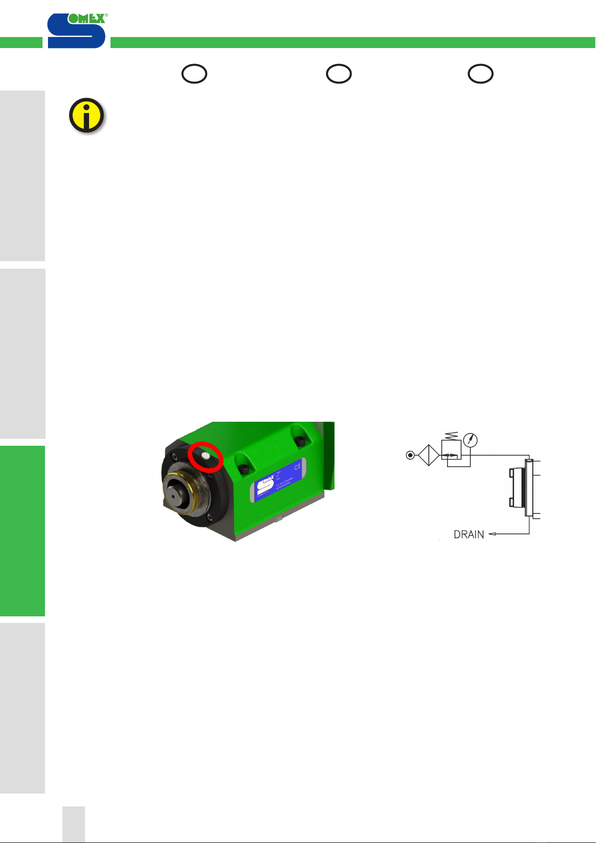
3.1.1 Pressurization
A draining hole under the front
cap is provide on these units.
Depending of unit utility and
environment, this draining hole
can be:
- leaved free
- choked
- screwed to a draining tube
- Used to maintain the spin-
delnose under pressure in case
of splash of lubricant.
Pressure: 0.7 bar Dry air
Connection: G1/8’’
In the delivery configuration of
the unit, the drain hole is bloc-
ked. (Except customer request).
3.1.2 Coolant through the tool
(Option)
Usage precautions
Filtering for cutting fluid:
5μm
Maximum pressure:
Coolant: 50bar
MQL: 10bar
No pressure of air in rotation
Do not use a rigid pipe in any
event.
Make sure that the hose is not
taut, and that it is not tensioned
when pressure is applied.
3.1 Maschine
3.1.1 Sperrlufttanschluss
Eine Öffnung von Entwäs-
serung-Druckbelüftung, die
unter der Deckel vorher gelegt
ist, ist auf diesen Einheiten
vorhergesehen.
Entsprechend der Benutzung
der Einheit und der Umgebung
kann diese Öffnung sein:
- Offen bleiben.
- Verschlossen werden.
- An einen Entlüftungsschlauch
angeschlossen werden.
- zum Druckhalten der Spindel-
nase wenn kühlmittelspritzer.
Druck: 0.7 bar Trockenluft An-
Trockenluft Anschluss: G1/8“
Serienmäßig ist die Einheit mit
geschlossener Entlüftungsöf-
fnung ausgestattet.
3.1.2 Kühlmittelzufuhr (Option)
Orsichtsmassnahmen bei
Verwendung:
Filtrierung der Kühlflüssigkeit:
5μm.
Maximaldruck:
Kühlmittel: 50 bar
MMS: 10bar
Kein Druck von Luft in die
Umdrehung
Niemals ein Rohr verwenden.
Überprüfen, dass der Schlauch
nicht gespannt ist und sich auch
nicht bei dem Unterdrucksetzen
spannt.
3.1 Machine
3.1.1 Pressurisation
Un orifice de drainage-pres-
surisation situé sous le flasque
avant est prévu sur ces unités.
En fonction de l’utilisation de
l’unité et du milieu ambiant, cet
orifice peut être :
- laissé libre
- obstrué
- raccordé à un tuyau de drai-
nage
- utilisé pour pressuriser le nez
de broche en cas de projection
de lubrifiant.
Pression: 0.7 bar air sec
Raccordements: G1/8’’
Dans la configuration de livrai-
son de l’unité, l’orifice de drai-
nage est obstrué. (sauf sur de-
mande client).
3.1.2 Arrosage par le centre
(Option)
Précautions d’utilisation:
Flitration du liquide de coupe:
5μm.
Pression maxi:
Huile de coupe: 50bar.
Micropulvérisation: 10bar
Pas de pression d’air en rota-
tion.
N’utiliser en aucun cas de tube
rigide.
S’assurer que le flexible ne soit
pas tendu et qu’il ne se tend pas
lors de la mise sous pression
1. Ind. relative à la sécurité
1. Sicherheitshinweis
1. Notes on safety
4. Maintenance / Entretien
4. Instandhaltung / Wartung
4. Service / Maintenance
3. Utilisation / Exploitation
3. Handhabung / Betrieb
3. Handling / Operation
2. Mise en service
2. Inbetriebnahme
2. Commissioning
16
DE GB
FR
1. Ind. relative à la sécurité
1. Sicherheitshinweis
1. Notes on safety
4. Maintenance / Entretien
4. Instandhaltung / Wartung
4. Service / Maintenance
3. Utilisation / Exploitation
3. Handhabung / Betrieb
3. Handling / Operation
2. Mise en service
2. Inbetriebnahme
2. Commissioning
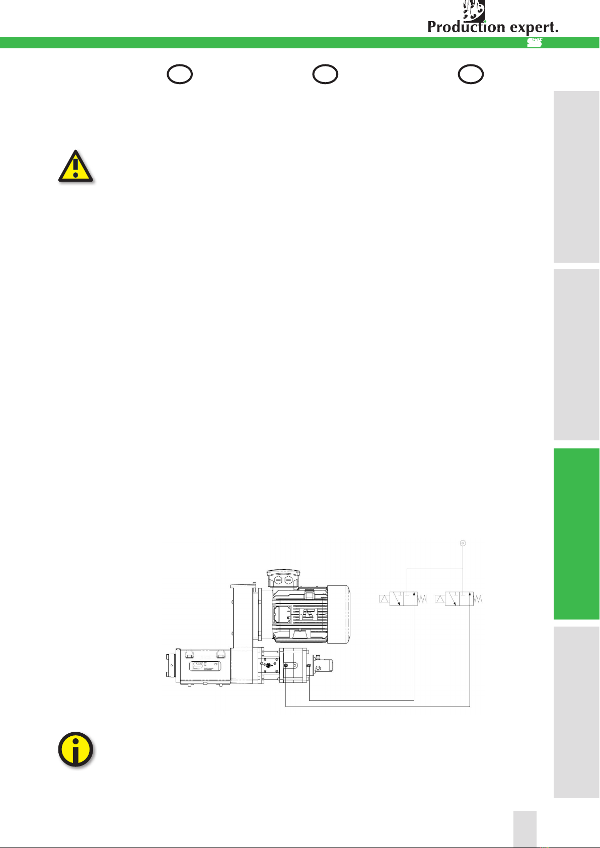
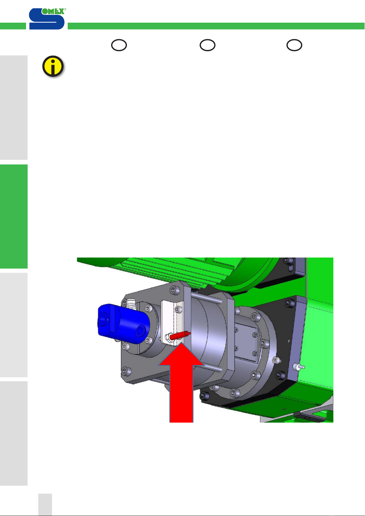
3.1.3 Tool holder clamping
The spindle must necessarily be
to a complete stop before ma-
neuvering the changing system
tools.
Operation:
Keeping the tool holder clam-
ped in the spindle cone is made
through a clamping device.
The effort to pull the tool in the
spindle is obtained thanks to a
stack of washers elastic type.
The release is done with a
pneumatic cylinder (pressure
service: 5 bar).
Connection:
The pressure air connection is
located at the rear part of the
unit (quick connect tube Ø6).
Before rotating the spindle, the
pneumatic cylinder must be in
its rear position (feed the return
jack, tube Ø6) and the detector
must have detected its position.
Example of pneumatic connec-
tions from the cylinder:
Somex S.A.S recommends
installing two 3/2 electro-
valves as shown above for
pneumatic ejection.
3.1.3 Spannen des Werkzeu-
ghalters
Die Spindel muss unbedingt
im völligen Stillstand sein, bevor
das Werkzeugspannsystem
betätigt wird.
Funktion:
Die Werkzeughalter werden
in der Spindel mittels einem
Spannsystem eingezogen. Das
Spannen erfolgt über Tellerfe-
dern, das Entspannen erfolgt
über ein Pneumatikzylinder (Be-
triebsdruck: 5 bar)
Anschluss:
für Schlauch Ø6 mm im hinte-
ren Bereich der Einheit Bevor
die Spindel zu drehen beginnt,
muss der P1 Anschluss des
Zylinders unter Druck gesetzt
werden (Anschluss Ø6 seitlich)
und es muss gewährleistet sein,
dass der Endschalter die hintere
Position des Zylinders erkennt.
Beispiel für den Anschlus des
hydraulischen Zylinders:
Somex S.A.S empfiehlt den
Einbau von zwei 3/2 Ma-
gnetventile , wie oben für die
pneumatische Ausstoß .
3.1.3 Serrage du porte outil
La broche doit impérativement
être à l’arrêt complet avant toute
manoeuvre du système de
changement d’outils.
Fonctionnement:
Le maintien des outils dans le
cône de l‘unité se fait grâce à
un serreur. L‘effort de traction
sur le porte-outil dans la broche
est obtenu grâce à un empilage
de rondelles de type élastiques.
Le desserrage se fait grâce à un
vérin pneumatique (pression de
service: 5 bar)
Raccordement:
Raccord qui se trouve à l‘arrière
de l‘unité (raccord rapide pour
tube Ø6). Avant la mise en rota-
tion de la broche, il faut alimen-
ter le retour vérin (raccord rapide
pour tube Ø6) qui se trouve sur
les chambres et s‘assurer que
le détecteur détecte la position
arrière du vérin.
Exemple de branchements du
vérin:
Somex S.A.S préconise
l’installation de deux élec-
trovannes 3/2 telle que re-
présentée ci-dessus pour
l’éjection pneumatique.
17
1. Ind. relative à la sécurité
1. Sicherheitshinweis
1. Notes on safety
2. Mise en service
2. Inbetriebnahme
2. Commissioning
3. Utilisation / Exploitation
3. Handhabung / Betrieb
3. Handling / Operation
4. Maintenance / Entretien
4. Instandhaltung / Wartung
4. Service / Maintenance
DEFR GB
3. Utilisation / Exploitation
3. Handhabung / Betrieb
3. Handling / Operation

3.1.4 Belt and pulley installation
for MAX COM
1) Drop front sheet
2) Unscrew fastening screws to
the motor flange
3) Loosen belt
4) Remove the clamping sys-
tem.
Proceed to the change
Remounting in reverse.
3.1.4 Wechsel von Riemen und
Riemenscheibe MAX COM
1) Abdezkung entfernen
2) Lösen der Schrauben am Mo-
torenflansch
3) Riemen lockern
4) Den Werkzeugspannsystems
entfernen
Riemen ersetzen
Montage in umgekehrter Rei-
henfolge.
3.1.4 Changement de l’en-
semble poulie/courroie MAX
COM
1) Déposer la tôle avant
2) Desserrer les vis de fixation
du flasque moteur
3) Détendre la courroie
4) Déposer le serreur pneuma-
tique
Procéder au changement
Remontage des opérations
dans le sens inverse
1. Ind. relative à la sécurité
1. Sicherheitshinweis
1. Notes on safety
4. Maintenance / Entretien
4. Instandhaltung / Wartung
4. Service / Maintenance
3. Utilisation / Exploitation
3. Handhabung / Betrieb
3. Handling / Operation
2. Mise en service
2. Inbetriebnahme
2. Commissioning
18
DE GB
FR
1. Ind. relative à la sécurité
1. Sicherheitshinweis
1. Notes on safety
4. Maintenance / Entretien
4. Instandhaltung / Wartung
4. Service / Maintenance
3. Utilisation / Exploitation
3. Handhabung / Betrieb
3. Handling / Operation
2. Mise en service
2. Inbetriebnahme
2. Commissioning

3.2 Tools
Handle tools with care; keep the
tools in a clean and sharp con-
dition, observe the instructions
of the tool manufacturer with re-
gard to the use of coolants and
tool holding devices.
Use the appropriate tools; do
not trim a tool for an application
for which it is not designed.
Always use speeds and feeds
which are assigned to the tool
and to the material without ex-
ceeding the maximum speed of
the machining unit.
Never remove the chips with
your bare hands; for this pur-
pose use chip hooks or the like.
3.2 Werkzeuge
Behandeln Sie Werkzeuge mit
Vorsicht; halten Sie die Werk-
zeuge sauber und scharf, be-
achten Sie die Anleitungen der
Werkzeughersteller bezüglich
Verwendung von Kühlmitteln
und Werkzeugaufnahmeeinrich-
tungen.
Verwenden Sie die zweckent-
sprechenden Werkzeuge; trim-
men Sie kein Werkzeug für eine
Anwendung, für die es nicht
konstruiert ist.
Verwenden Sie immer Dreh-
zahlen und Vorschübe, die dem
Werkzeug und Werkstoff zuge-
ordnet sind ohne die maximale
Drehzahl der Bearbeitungsein-
heit zu überschreiten.
Entfernen Sie Späne nie mit der
bloßen Hand, benutzen
3.2 Outillage
Traitez les outils avec pré-
caution; maintenez les outils
propres et affûtés, observez
les instructions des fabricants
d’outillage lors d’utilisation de
liquides de refroidissement et
de dispositifs de fixation d’outils.
Utilisez des outils conformes à
la destination, n’adaptez aucun
outil pour une application pour
laquelle il n’est pas construit.
Utilisez toujours des vitesses de
rotation et des avances appro-
priés à l’outillage et à la matière,
sans dépasser la vitesse de
rotation maximale de l’unité de
travail.
Veillez à ne jamais enlever les
copeaux à la main, utilisez pour
cela des crochets à copeaux ou
des dispositifs analogues
19
1. Ind. relative à la sécurité
1. Sicherheitshinweis
1. Notes on safety
2. Mise en service
2. Inbetriebnahme
2. Commissioning
3. Utilisation / Exploitation
3. Handhabung / Betrieb
3. Handling / Operation
4. Maintenance / Entretien
4. Instandhaltung / Wartung
4. Service / Maintenance
DEFR GB
3. Utilisation / Exploitation
3. Handhabung / Betrieb
3. Handling / Operation
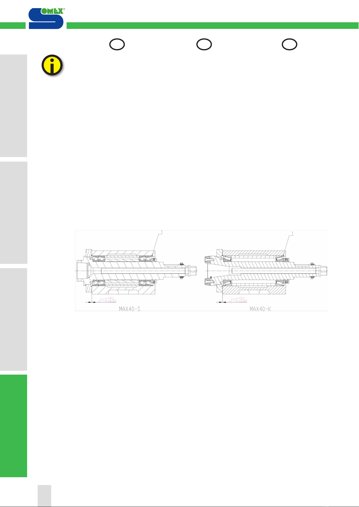
4.1 Preventive mainte-
nance
4.1.1 Spindle bearing lubrica-
tion:
The bearings are lifetime greased with
LUBCON Turmogrease Highspeed
L252 grease, not miscible with any
other grease.
4.1.2 Bearing adjustment:
Adjust gap J by adjusting the thick-
ness of the ring (1) if necessary.
4.1 Vorbeugende Instand-
haltung
4.1.1 Schmierung der Spindella-
ger:
Die lager werden lebenszeit mit fol-
gendem fett geschmiert LUBCON
Turmogrease Highspeed L252 ist mit
keinem anderem Fett mischbar.
4.1.2 Lagerpassung:
Das spiel J durch Austrichten des
Ringes (1) einstellen
4.1 Maintenance préven-
tive
4.1.1 Graissage des roulement:
Les roulements sont graissés à vie
à la graisse LUBCON turmogrease
Highspeed L252 non miscible avec
tout autre graisse.
4.1.2 Réglage des roulements:
Régler le jeu J par rectification éven-
tuelle de la bague (1)
1. Ind. relative à la sécurité
1. Sicherheitshinweis
1. Notes on safety
4. Maintenance / Entretien
4. Instandhaltung / Wartung
4. Service / Maintenance
3. Utilisation / Exploitation
3. Handhabung / Betrieb
3. Handling / Operation
2. Mise en service
2. Inbetriebnahme
2. Commissioning
20
DE GB
FR
1. Ind. relative à la sécurité
1. Sicherheitshinweis
1. Notes on safety
4. Maintenance / Entretien
4. Instandhaltung / Wartung
4. Service / Maintenance
2. Mise en service
2. Inbetriebnahme
2. Commissioning
4. Maintenance / Entretien
4. Instandhaltung / Wartung
4. Service / Maintenance
This manual suits for next models
1
Popular Industrial Electrical manuals by other brands

Murata
Murata GRM1555C1HR60BA01 Series Reference sheet

ABB
ABB Zenith ZT30 Operation and maintenance manual

Murata
Murata GQM2195C1H270GB01 Series Reference sheet

Keysight Technologies
Keysight Technologies Ixia XGS12 Assembly guide

Murata
Murata GQM2195C2E150GB12 Series Reference sheet

Murata
Murata GJM0335C1ER39WB01 Series Reference sheet


