manuals.online logo
Brands
  1. Home
  2. •
  3. Brands
  4. •
  5. schmersal
  6. •
  7. Industrial Electrical
  8. •
  9. schmersal SLB 200 Series User manual

schmersal SLB 200 Series User manual

1
SLB 200
Operating instructions
Safety light barrier
EN
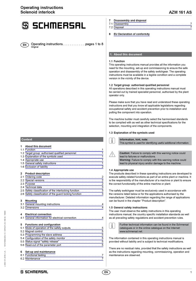
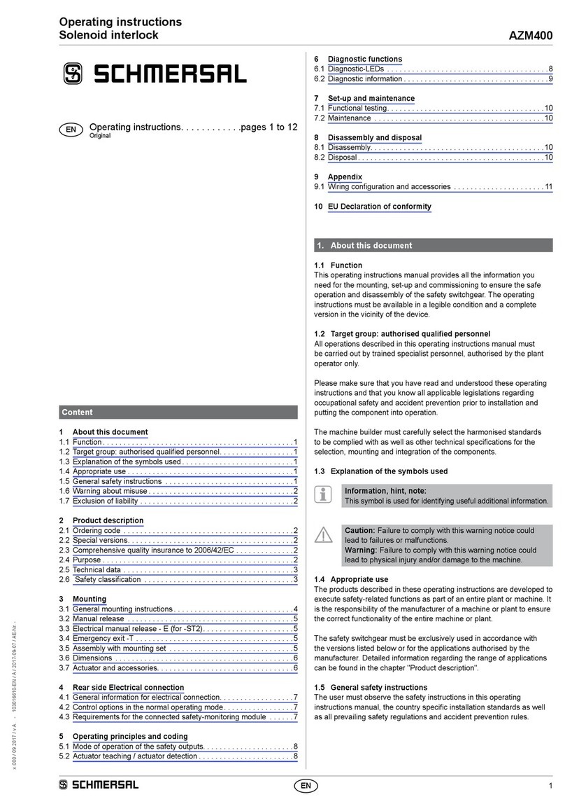
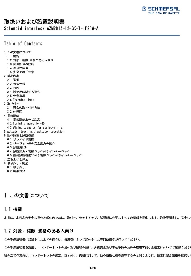
1. About this document
1.1 Function
This operating instructions manual provides all the information you
need for the mounting, set-up and commissioning to ensure the safe
operation and disassembly of the safety switchgear. he operating
instructions must be available in a legible condition and a complete
version in the vicinity of the device.
1.2 Target group: authorised qualified personnel
All operations described in this operating instructions manual must
be carried out by trained specialist personnel, authorised by the plant
operator only.
Please make sure that you have read and understood these operating
instructions and that you know all applicable legislations regarding
occupational safety and accident prevention prior to installation and
putting the component into operation.
The machine builder must carefully select the harmonised standards
to be complied with as well as other technical specifications for the
selection, mounting and integration of the components.
1.3 Explanation of the symbols used
Information, hint, note:
This symbol is used for identifying useful additional information.
Caution: Failure to comply with this warning notice could
lead to failures or malfunctions.
Warning: Failure to comply with this warning notice could
lead to physical injury and/or damage to the machine.
1.4 Appropriate use
The products described in these operating instructions are developed to
execute safety-related functions as part of an entire plant or machine. It
is the responsibility of the manufacturer of a machine or plant to ensure
the correct functionality of the entire machinery or plant.
The safety switchgear must be exclusively used in accordance with the
versions listed below or for the applications authorised by the manufac-
turer. Detailed information regarding the range of applications can be
found in the chapter "Product description".
1.5 General safety instructions
The user must observe the safety instructions in this operating instruc-
tions manual, the country-specific installation standards as well as all
prevailing safety regulations and accident prevention rules.
Further technical information can be found in the Schmersal
catalogues or in the online catalogue on the Internet:
www.schmersal.net.
The information contained in this operating instructions manual is
provided without liability and is subject to technical modifications.
There are no residual risks, provided that the safety instructions as well
as the instructions regarding mounting, commissioning, operation and
maintenance are observed.
1.6 Warning about misuse
In case of improper use or manipulation of the safety
switchgear, personal hazards or damages to machinery
or plant components cannot be excluded when safety
switchgear is used. The relevant requirements of the
standards ISO 13855 and ISO 13857 must be observed.
Content
1 About this document
1.1 Function ..............................................1
1.2 ..................1
1.3 Explanation of the symbols used ...........................1
1.4 Appropriate use ........................................1
1.5 General safety instructions ...............................1
1.6 Warning about misuse ...................................1
1.7 Exclusion of liability .....................................2
2 Product description
2.1 Ordering code .........................................2
2.2 Special versions........................................2
2.3 Destination and use .....................................2
2.4 Technical data .........................................2
2.5  .....................................2
3 Mounting
3.1 General mounting instructions .............................2
3.2 Dimensions ...........................................3
4 Electrical connection
4.1 General information for electrical connection..................3
5 Set-up and maintenance
5.1 Functional testing.......................................3
5.2 Maintenance ..........................................3
6 Disassembly and disposal
6.1 Disassembly...........................................3
6.2 Disposal ..............................................3
04.2015-EN
EN Operating instructions. . . . . . . . . . . . .pages 1 to 4
Translation of the original operating instructions
2
Operating instructions
Safety light barrier SLB 200
EN
1.7 Exclusion of liability
We shall accept no liability for damages and malfunctions resulting from
defective mounting or failure to comply with this operating instructions
manual. The manufacturer shall accept no liability for damages result-
ing from the use of unauthorised spare parts or accessories.
For safety reasons, invasive work on the device as well as arbitrary re-
pairs, conversions and modifications to the device are strictly forbidden;
the manufacturer shall accept no liability for damages resulting from
such invasive work, arbitrary repairs, conversions and/or modifications
to the device.
2. Product description
2.1 Ordering code
SLB 200-
➀
31-21
No. Option Description
➀
E Transmitter
R Receiver
2.2 Special versions
For special versions, which are not listed in the order code below 2.1,
these specifications apply accordingly, provided that they correspond to
the standard version.
2.3 Destination and use
In combination with the SLB200-C04-1R safety-monitoring module, the
SLB 200-E/R31-21 one-way safety light barriers are a non-contact safe-
ty guard (ESD, electro-sensitive device) for the protection of hazardous
areas on power-driven work equipment.
LED status indication
Red LED on Light beam interrupted
Green LED on Light beam clear
Green-red flashing mode Soiling, misalignment, distance between
transmitter and receiver too large
The entire concept of the control system, in which the safety
component is integrated, must be validated to the relevant
standards.
2.4 Technical data
Standards: IEC 61496-1
Enclosure: ABS
10 % GF
Enclosure dimensions: 31 x 50.5 x 19 mm
Termination:
- Transmitter: 10 cm cable with M8 connector, 3-pole
- Receiver: 10 cm cable with M8 connector, 4-pole
Max. cable length: 50 m
Protection class: IP67
Response time: 30 ms, in combination with SLB 200-C04-1R
safety monitoring module
Range: 4 m
Start/restart interlock: yes, in combination with SLB 200-C04-1R
safety monitoring module
Contactor control: yes, in combination with SLB 200-C04-1R
safety monitoring module
Light emission wavelength: 880 nm
Rated operating voltage Ue:24 VDC ± 20%
Safety outputs: yes, in combination with SLB 200-C04-1R
safety monitoring module
Angle of radiation: ± 4°
Min. size of object: 9 mm Ø
LED status indication: soiling, switching condition and power on
Ambient temperature: –10 °C … + 55 °C
Storage and transport temperature: – 20 °C … + 80 ºC
2.5 Safety classification
(in combination with SLB 200-C04-1R safety monitoring module)
Standards: ISO 13849-1, IEC 61508, IEC 62061
PL: d
Control Category: 2
PFH value: 4 x 10⁻⁹/h
SIL: suitable for SIL 2 applications
Service life: 20 years
3. Mounting
3.1 General mounting instructions

without BF 31 mounting angle). The mounting possibilities are shown
on the dimensional drawing.

and at the same mounting height.

the point at which the LED indication changes from red to green.

in central position.

to red continuous signal during this process.
Please also observe the notes for the calculation of the
safety distance in the operating instructions manual of
the SLB 200-C04-1R safety-monitoring module.
3
SLB 200
Operating instructions
Safety light barrier
EN
3.2 Dimensions
All measurements in mm.
9,6
R7
6,75
20°
18,8
30,8
39,4
50,3
43,4
24
5,5
15,5
20
16,1
10
ø 8,5 (6x)
ø4,4 (3x)
ø10
4. Electrical connection
4.1 General information for electrical connection
The electrical connection may only be carried out by
authorised personnel in a de-energised condition.
Transmitter
SLB 200-E31-21
4
3
1
PIN Description
1 BN
3 n.c.
4 WH
Receiver
SLB 200-R31-21
31
42
PIN Description
1 BN
2 WH
3 n.c.
4 n.c.
Further information about the wiring and connection of
the safety light barrier to the safety-monitoring module
can be found in the operating instructions manual of the
SLB 200-C04-1R safety-monitoring module.
5. Set-up and maintenance
5.1 Functional testing
The safety function of the safety components must be tested. The
following conditions must be previously checked and met:
1. Correct fixing of the transmitter and receiver.
2. Fitting and integrity of the power cable.
3. If one or more light barriers are interrupted, the hazardous
movement is brought to standstill.
5.2 Maintenance
In the case of correct installation and adequate use, the safety switch-
gear features maintenance-free functionality. A regular visual inspection
and functional test, including the following steps, is recommended:
1. Check the correct mounting of the fixing screws on the safety
light barriers.
2. Clean the optics of transmitter and receiver with a soft clean cloth.
The use of agressive, abrasive or scratching cleaning agents,
which could attack the surface, is prohibited
Damaged or defective components must be replaced.
6. Disassembly and disposal
6.1 Disassembly
The safety switchgear must be disassembled in a de-energised
condition only.
6.2 Disposal
The safety switchgear must be disposed of in an appropriate manner in
accordance with the national prescriptions and legislations.
K. A. Schmersal GmbH & Co. KG
Möddinghofe 30, D - 42279 Wuppertal
Postfach 24 02 63, D - 42232 Wuppertal
Phone: +49 - (0)2 02 - 64 74 - 0
Telefax: +49 - (0)2 02 - 64 74 - 1 00
E-Mail: [email protected]
Internet: http://www.schmersal.com

Other schmersal Industrial Electrical manuals

schmersal AZM40 User manual

schmersal

schmersal AZM40 User manual

schmersal AZM201Z-CC-T-1P2PW-DU User manual

schmersal

schmersal AZM201Z-CC-T-1P2PW-DU User manual

schmersal TZF SPEZ User manual

schmersal

schmersal TZF SPEZ User manual

schmersal AZM 161 AS User manual

schmersal

schmersal AZM 161 AS User manual

schmersal AZM400 User manual

schmersal

schmersal AZM400 User manual

schmersal AZM201Z-I1-ST2-T-1P2PW User manual

schmersal

schmersal AZM201Z-I1-ST2-T-1P2PW User manual

schmersal AZM201Z-ST2-T-SD2P-A User manual

schmersal

schmersal AZM201Z-ST2-T-SD2P-A User manual

schmersal AZM201Z-I2-SK-T-1P2PW-A User manual

schmersal

schmersal AZM201Z-I2-SK-T-1P2PW-A User manual

Popular Industrial Electrical manuals by other brands

Murata GRM319R72A102KA01 Series Reference sheet

Murata

Murata GRM319R72A102KA01 Series Reference sheet

Vahle VKS10 Translation of the original instructions

Vahle

Vahle VKS10 Translation of the original instructions

Murata GRM155R60J102KA01 Series Reference sheet

Murata

Murata GRM155R60J102KA01 Series Reference sheet

Siemens 3WX3666-8JA0 Series operating instructions

Siemens

Siemens 3WX3666-8JA0 Series operating instructions

Murata GRM32EC81E226KE15 Series Reference sheet

Murata

Murata GRM32EC81E226KE15 Series Reference sheet

Murata GRM31C5C1E104JA01 Series Reference sheet

Murata

Murata GRM31C5C1E104JA01 Series Reference sheet

Murata GRM0335C1E4R5CA01 Series Reference sheet

Murata

Murata GRM0335C1E4R5CA01 Series Reference sheet

Murata GRM21BR70J106KE76 Series Reference sheet

Murata

Murata GRM21BR70J106KE76 Series Reference sheet

TE Connectivity SOLARLOK 1954283-1 instruction sheet

TE Connectivity

TE Connectivity SOLARLOK 1954283-1 instruction sheet

boink Inmate QX7 Mounting instructions

boink

boink Inmate QX7 Mounting instructions

Murata GRM033R61E392MA12 Series Reference sheet

Murata

Murata GRM033R61E392MA12 Series Reference sheet

Murata GJM0335C1H3R5BB01 Series Reference sheet

Murata

Murata GJM0335C1H3R5BB01 Series Reference sheet

Murata GRM0335C1E2R7BA01 Series Reference sheet

Murata

Murata GRM0335C1E2R7BA01 Series Reference sheet

Murata GRM0335C1H7R4BA01 Series Reference sheet

Murata

Murata GRM0335C1H7R4BA01 Series Reference sheet

ABB Tmax RC223 T3 manual

ABB

ABB Tmax RC223 T3 manual

Murata GRM1555C1H200JA01 Series Reference sheet

Murata

Murata GRM1555C1H200JA01 Series Reference sheet

Murata GRM155R60J224ME01 Series Reference sheet

Murata

Murata GRM155R60J224ME01 Series Reference sheet

Murata GRM32ER61E226KE15 Series Reference sheet

Murata

Murata GRM32ER61E226KE15 Series Reference sheet

manuals.online logo
manuals.online logoBrands
  • About & Mission
  • Contact us
  • Privacy Policy
  • Terms and Conditions

Copyright 2025 Manuals.Online. All Rights Reserved.