SOMFY 1782100 User manual

545 812
REFERENCES
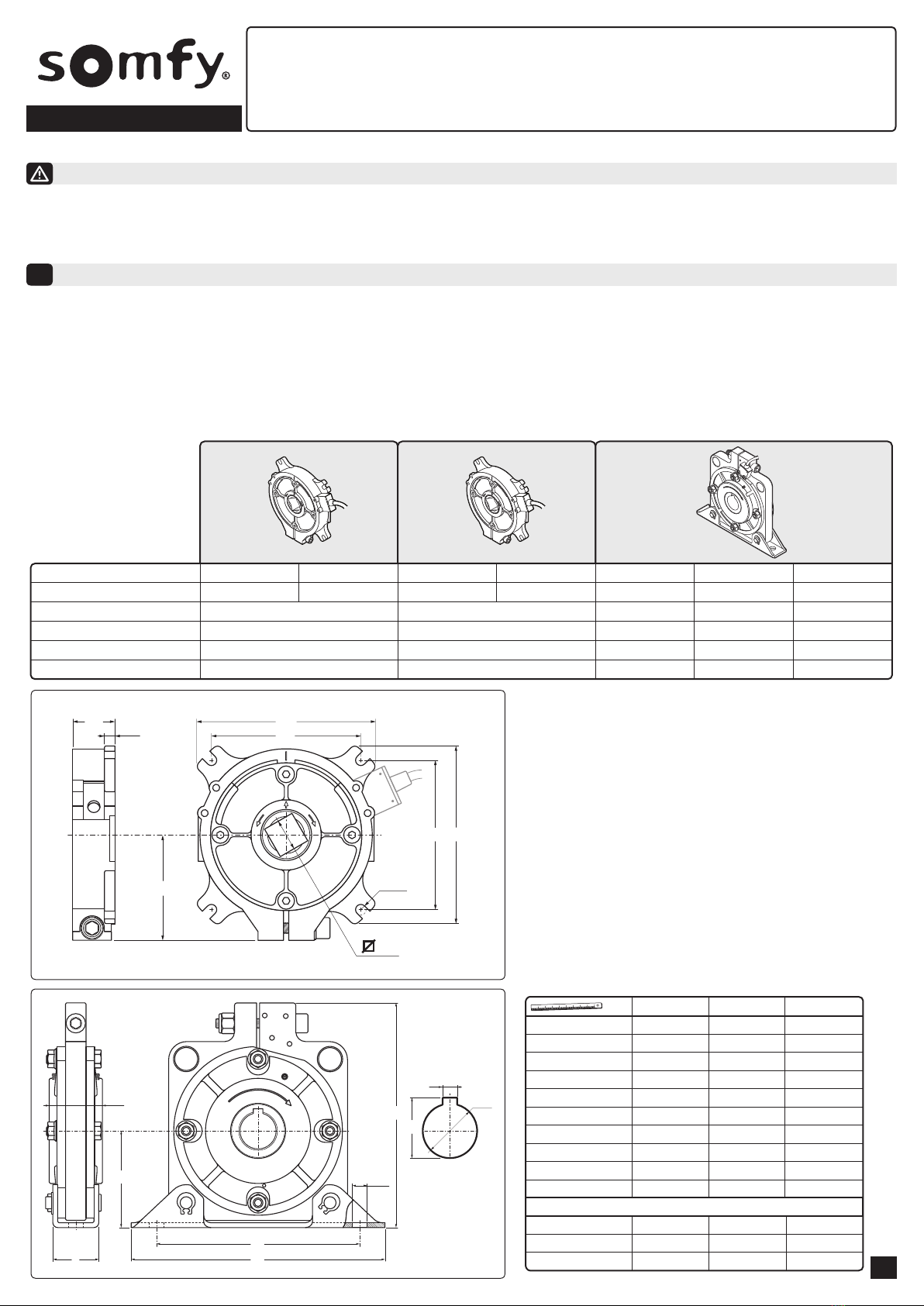
COUPLE ADMISSIBLE (N.m)
MOMENT D'ARRET MAX. (N.m)
VITESSE DE FONCTIONNEMENT (tr/min)
POIDS UNITAIRE (kg)
95
545
22
1
147
812
22
1
332
796
22
4,5
552
1253
22
8
1063
4092
18
LONGUEUR DU CÂBLE
1 m5m1m5m1m1m1m
23
1782097 1782098 1782099 1782100 1782101 1782102 1782103
FR ANTICHUTES
SOMFY SAS, 50 avenue du Nouveau Monde 74300 CLUSES - FRANCE - & (33) 4 50 96 70 00 - capital 20.000.000 !- RCS Bonneville 303.970.230
5071776A
Read carefully these instructions before any use.
1/4
Caractéristiques techniques
1
- Lisez attentivement ce manuel d’instructions qui accompagne cet antichute. Il fournit d’importantes indications concernant la sécurité, l’installation,
l’utilisation et l’entretien. Ce dispositif de sécurité doit être installé par un technicien qualifié. Avant l’installation, vérifier si l’antichute est adapté au
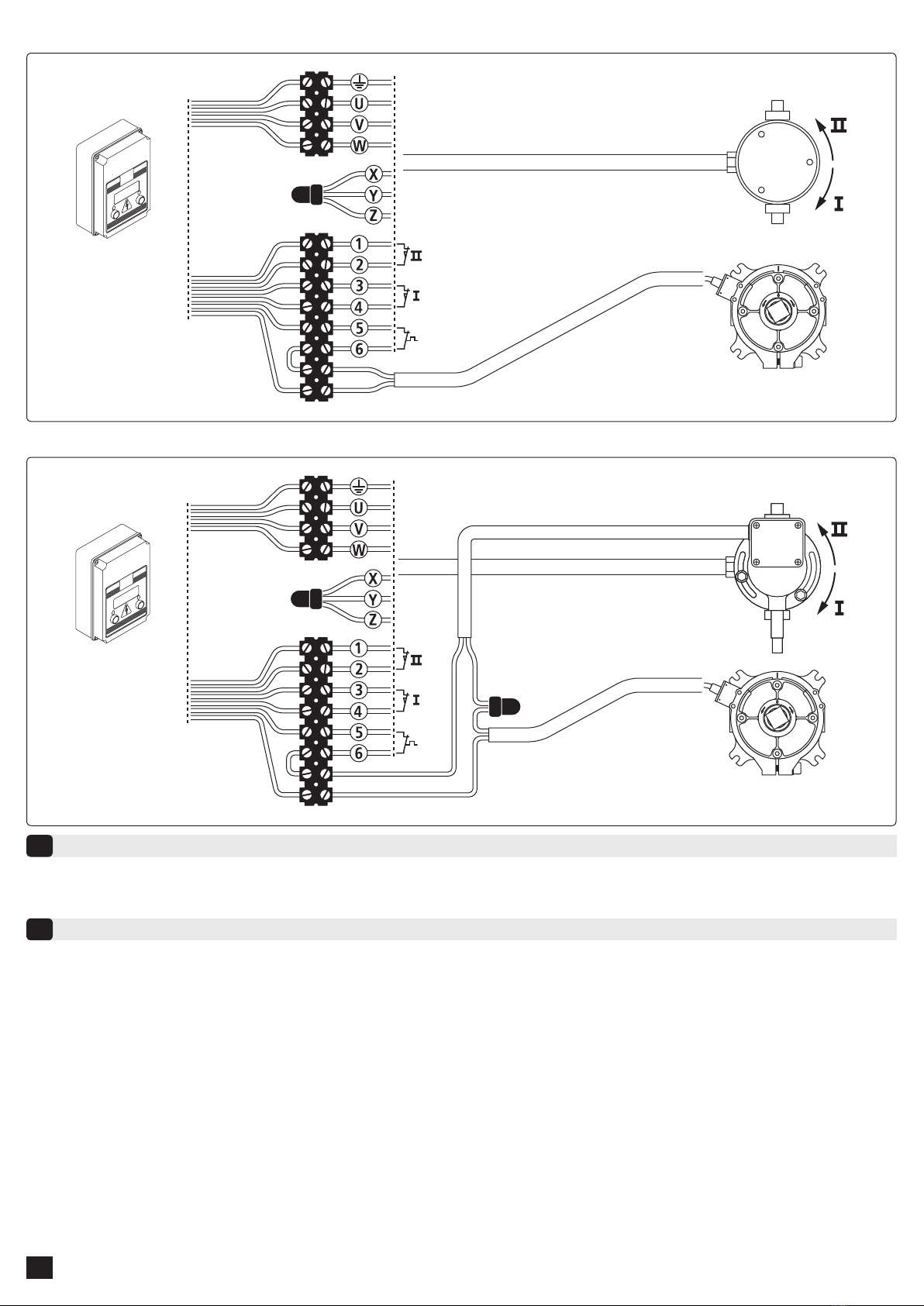
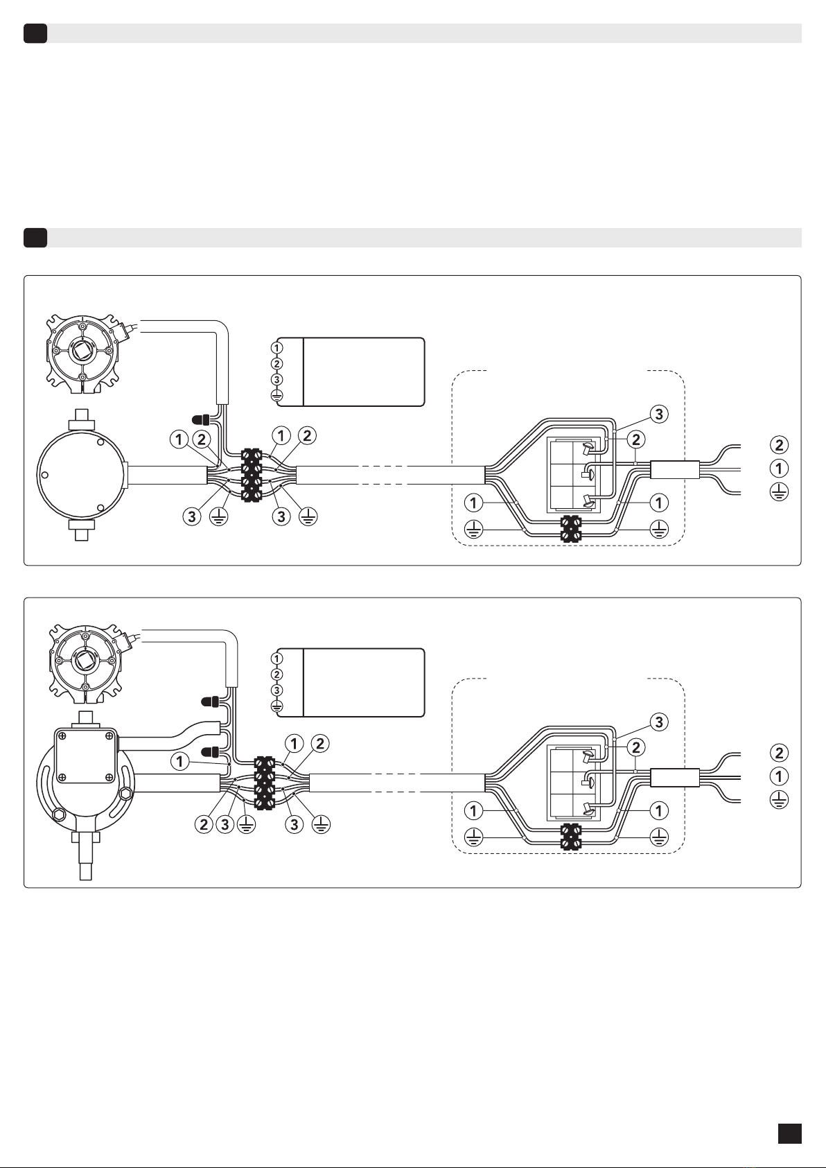
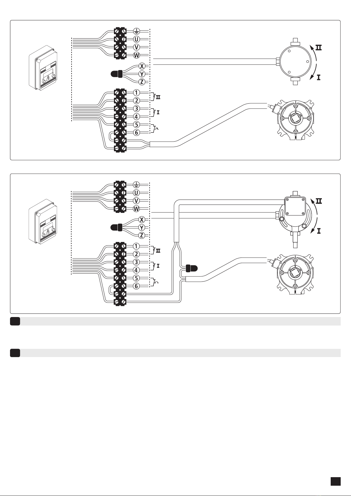
poids du rideau et au diamètre du tube. Ce dispositif de sécurité doit être câblé au moteur ou au coffret de commande.
L’antichute est un appareillage mécanique de sécurité pour volets roulants, rideaux métalliques et grilles avec une double fonction :
- Support de l’axe.
- Antichute en cas d’une brusque accélération dans le sens descente du volet.
Les antichutes ont un corps central creux où s’insère la bobine de l’axe d’enroulement. Les antichutes SOMFY sont équipés d’un système
d’amortissement de l’impact et d’un dispositif coupant l’alimentation électrique du moteur au moment où l’antichute se déclenche.
Important : Choisir l'antichute en fonction des abaques fournis dans le catalogue SOMFY et selon les caractéristiques de l'installation (poids
et hauteur du rideau, diamètre de l'axe)
18
10185
Ø 6,3
60
85
101
24 6,5
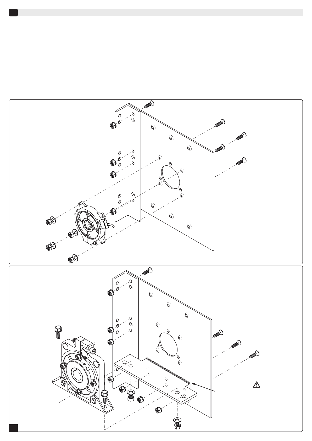
Visserie (non fournie) :
- 4 vis M6 x 20 DIN 912 Zn 8.8
- 4 écrous HU6 DIN 934
- 4 rondelles Ø 6,4 x Ø18 x 1,6 DIN 9021 Zn
G
T
C
H
Ø I
B
E
Ø D
F
A
A
B
C
Ø D h7
E
332 N.m
210
44
80
30
38
552 N.m
260
50
100
40
45
1063 N.m
340
78
150
50
75
F180 230 300
G185 225 320
H J9 81214
Ø I 12 14 22
T33,3 43,3 53,8
DIN 933 M10x30 Zn 8.8 DIN 933 M12x40 Zn 8.8 DIN 933 M20x55 Zn 8.8
DIN 125 Ø10,5 Zn DIN125 Ø21 Zn
DIN 934 M10 Zn
DIN 125 Ø13 Zn
DIN 934 M12 Zn DIN 934 M20 Zn
mm
VISSERIE (non fournie)
VIS (x 2)
RONDELLE (x 2)
ECROU (x 2)

5065411
5071279
5065411
5071279
5071254
CORDON DE SOUDURE OBLIGATOIRE
MANDATORY WELDING BEAD
Instructions pour l'installation
2
Lors de l’installation il faut faire attention aux indications suivantes :
1. L’antichute doit toujours être installé en position opposée au moteur et à l’extérieur de la plaque. Le sens de rotation "OBEN" correspond
au sens descente du rideau.
2. L’antichute doit être fixé de manière que le câble du micro-interrupteur sorte vers le haut pour les antichutes 95 et 147 N.m. Un seul sens de
montage sur la plaque (ils fonctionnent dans les deux sens de rotation).
3. Les antichutes 332 N.m, 552 N.m et 1063 N.m doivent être positionnés horizontalement avec un écart non supérieur à ± 3°. Des angles diffé-
rents produisent des variations dans la vitesse d’intervention et donc un risque de mauvais fonctionnement.
4. Utiliser les vis de fixation recommandées §1.
5. La bobine côté opposé au moteur doit être soudée ou fixée de manière concentrique sur le tube d’enroulement.
6. La bobine côté opposé au moteur doit être insérée dans l’axe de l’antichute sans le forcer. Contrôler éventuellement l’alignement entre le trou
de l’antichute et le moteur.
7. Eviter la manœuvre par à coup du volet pour ne pas provoquer l’intervention de l’antichute. Un guide latéral bien construit et des faces soli-
des sont la garantie d’un fonctionnement régulier.
8. Connecter l’antichute au moteur ou au boîtier de commande (voir câblage page 3/4 & 4/4).
95 & 147 N.m
332, 552 & 1063 N.m
2/4

5
1
3
Interrupteur unipolaire
PE
N
L
VERT/JAUNE - GREEN/YELLOW
BLEU - BLUE
MARRON - BROWN
NOIR - BLACK
Unipolar switch
L
N
PE
ANTICHUTE / SAFETY BRAKE
PE
N
L
VERT/JAUNE - GREEN/YELLOW
BLEU - BLUE
MARRON - BROWN
NOIR - BLACK
5
1
3
Interrupteur unipolaire
Unipolar switch
L
N
PE
Dispositions pour l'essai
3
Câblage des antichutes
4
La procédure d’essai de l’antichute prévoit les opérations suivantes :
1. Un contrôle soigné de l’installation, en faisant attention que toutes les vis de fixation de l’antichute soient équipées des rondelles adéqua-
tes et soient bien serrées.
2. Vérifier que l’antichute fonctionne régulièrement pendant le mouvement du volet . A défaut de pouvoir simuler une rupture accidentelle de
la transmission, le bon fonctionnement peut être vérifié en écoutant le tintement provoqué par la chute des rouleaux de blocage internes.
Si l’on entend clairement ce tintement, l’antichute a réussi l’essai de fonctionnement.
En cas de déclenchement de l’antichute :
1. Sécuriser l'installation.
2. Démonter et contrôler les éléments défectueux et les remplacer si nécessaire.
3. Retourner l'antichute à SOMFY pour remise en service.
Câblage avec motorisation monophasée sans manœuvre de secours :
Câblage avec motorisation monophasée avec manœuvre de secours :
3/4

SD 250
SD 410
ANTICHUTE
SAFETY BRAKE
SD 250
SD 410
ANTICHUTE
SAFETY BRAKE
Câblage avec motorisation triphasée sans manœuvre de secours :
Câblage avec motorisation triphasée avec manœuvre de secours :
Les matériaux et les composants utilisés pour la construction des antichutes ont été choisis afin d’en éviter l’entretien.
Cette gamme de produits répond à la directive RoHs ainsi qu'aux normes suivantes :
EN 13241-1 : 2003
EN 12604 : 2000
EN 12605 : 2000
Maintenance
5
Normes
6
4/4

GB SAFETY BRAKES
SOMFY SAS, 50 avenue du Nouveau Monde 74300 CLUSES - FRANCE - & (33) 4 50 96 70 00 - capital 20.000.000 !- RCS Bonneville 303.970.230
5071776A
Read carefully these instructions before any use.
1/4
REFERENCES
NOMINAL TORQUE (N.m)
MAX. LOCKING TORQUE (N.m)
OPERATING SPEED (rpm)
WEIGHT (kg)
1782097
95
545
22
1
1782098 1782099 1782100
147
812
22
1
1782101
332
796
22
4,5
1782102
552
1253
22
8
1782103
1063
4092
18
CABLE LENGTH
1 m5m1m5m1m1m1m
23
A
B
C
Ø D h7
E
332 N.m
210
44
80
30
38
552 N.m
260
50
100
40
45
1063 N.m
340
78
150
50
75
F180 230 300
G185 225 320
H J9 81214
Ø I 12 14 22
T33,3 43,3 53,8
DIN 933 M12x40 Zn 8.8 DIN 933 M20x55 Zn 8.8
DIN125 Ø21 ZnDIN 125 Ø13 Zn
DIN 934 M12 Zn DIN 934 M20 Zn
mm
DIN 933 M10x30 Zn 8.8
DIN 125 Ø10,5 Zn
DIN 934 M10 Zn
SCREWS (not provided)
SCREW (x 2)
WASHER (x 2)
NUT (x 2)
Technical data
1
- This product is supplied with an “Instruction Manual” which should be read carefully as it provides important information about safety,
installation,operation and maintenance. This safety device must be install by a qualified technician. Before the installation, check if the safety brake
is adapted according to the weight of the shutter and the diameter of the tube. This safety device must be connect with the motor or the control box.
The safety brake is a safety device for rolling blinds, metallic shutters and grills performing two functions:
- A bearing support for the blind shaft.
- A mechanical brake to stop the descent of the blind if sudden acceleration occurs.
The safety brake is made up of a central body with a hole in which the rolling blind shaft journal is inserted. The safety brake is equipped with
a shock-absorbing system and a micro switch in order to disconnect the electrical supply to gear motor when the brake locks.
Important: choose the safety brake according to the characteristics of the installation (weight and height of the curtain, diameter of the tube
and the abacus available in the SOMFY catalogue.
18
10185
Ø 6,3
60
85
101
24 6,5
Screws (not provided) :
- 4 x screws M6 x 20 DIN 912 Zn 8.8
- 4 x nuts HU6 DIN 934
- 4 x washers Ø 6,4 x Ø18 x 1,6 DIN 9021 Zn
G
T
C
H
Ø I
B
E
Ø D
F
A

5065411
5071279
5065411
5071279
5071254
CORDON DE SOUDURE OBLIGATOIRE
MANDATORY WELDING BEAD
Installation instructions
2
During the installation please pay attention to the following instructions:
1. Always install the safety brake opposite to the motor and outside of the plate. The direction of rotation "OBEN" corresponds to the down
direction.
2. Install the safety brake with the micro-switch cable on the top for the 95 and 147 N.m. Only one direction of assembly on the plate (they
function in the two directions of rotation).
3. Install the safety brake in square, in any case with a deviation not exceeding ± 3°. Different angles will vary the locking speed and may cause
a bad operation of the system.
4. Use the safety brake fastening screws recommended §1.
5. Weld the bobbin concentrically to the tube.
6. Insert the square support pin (or the pin with key) of the shaft into the safety brake hole smoothly. Eventually check the alignement between
the hole of the safety brake, on one side, and the motor hollow shaft on the other side.
7. Avoid a snapping working of the shutter since it might cause the safety brake to intervene. A well-built side slide and good profiles assure a
regular working of the device.
8. Wire the safety brake to the motor or to the control box. (see wiring page 3/4 & 4/4).
95 & 147 N.m
332, 552 & 1063 N.m
2/4

3/4
5
1
3
Interrupteur unipolaire
PE
N
L
VERT/JAUNE - GREEN/YELLOW
BLEU - BLUE
MARRON - BROWN
NOIR - BLACK
Unipolar switch
L
N
PE
ANTICHUTE / SAFETY BRAKE
PE
N
L
VERT/JAUNE - GREEN/YELLOW
BLEU - BLUE
MARRON - BROWN
NOIR - BLACK
5
1
3
Interrupteur unipolaire
Unipolar switch
L
N
PE
Testing instructions
3
Wiring of safety brakes
4
To test the operation of the safety brake:
1. Check accurately the installation and make sure that all the fastening screws of the safety brake are provided with suitable washers and
perfectly tightened.
2. Check the safety brake regular working while the shutter is in rotation. Since it is not possible to simulate a breakage in the transmission
you can make sure of the good working of the safety brake by listening to the clinking caused by the fall of the inner locking rollers. If it can
be clearly heard, the safety brake has succeeded the working test.
In case of triggering of the safety brake:
1. Secure the installation.
2. Remove and check the faulty elements , replace them if necessary.
3. Send back the safety brake to SOMFY for verification and reset.
Wiring with a single-phase motor without manual override:
Wiring with a single-phase motor with manual override:

4/4
SD 250
SD 410
ANTICHUTE
SAFETY BRAKE
SD 250
SD 410
ANTICHUTE
SAFETY BRAKE
Wiring with a 3-phases motor without manual override:
Wiring with a 3-phases motor with manual override:
The materials and the components used for the construction of the safety brake have been specially selected in order not to require
any kind of maintenance.
This range of products is conform to the RoHs directive and the following standard:
EN 13241-1 : 2003
EN 12604 : 2000
EN 12605 : 2000
Maintenance
5
Standards
6
This manual suits for next models
6
Table of contents
Languages:
Popular Home Safety Product manuals by other brands

SECO-LARM
SECO-LARM Enforcer SD-7201GC-PE1 Specification sheet

Electia
Electia CTC-909B user manual

Intelligent Motion Systems
Intelligent Motion Systems MDI34 Specification manual

Perma
Perma 2741 instructions

Sonic Alert
Sonic Alert HomeAware HA360MVSB manual

Heath Zenith
Heath Zenith Motion Sensor Light 7101 Installation