Sondermann MAGSON MAS Type 4 User manual

MAGSON magnetically coupled self-priming
centrifugal pumps
MAS types 4-6
Operating Manual

2
Table of Contents
1. Declaration of conformity.........................................................5
2. Basic information......................................................................7
2.1 Notes on the operating manual .................................................................7
2.2 Validity of data.........................................................................................7
2.3 Purpose ................................................................................................... 7
2.4 Use to the intended purpose ..................................................................... 7
2.5 Anticipated misuse.................................................................................... 8
2.6 Limits of use ............................................................................................8
2.7 Warranty and liability................................................................................8
2.8 Contact details ......................................................................................... 8
3. Safety ........................................................................................9
3.1 Standards and directives...........................................................................9
3.2 Depiction of safety instructions................................................................ 10
3.3 Symbols used......................................................................................... 10
4. Technical Information.............................................................11
4.1 General description................................................................................. 11
4.2 Nameplate ............................................................................................. 11
4.3 Types MAGSON MAS............................................................................... 11
4.4 Type codes and materials........................................................................ 12
4.5 Structure of MAGSON MAS...................................................................... 14
5. Transport and temporary storage ..........................................15
5.1 Safety instruction.................................................................................... 15
5.2 Transport............................................................................................... 15
5.3 Temporary storage................................................................................. 15
6. Installation..............................................................................15
6.1 Safety precautions.................................................................................. 15
6.2 Installation requirements ........................................................................ 15
6.3 Installation............................................................................................. 16
6.3.1 Hose and pipe lines...................................................................... 16
6.3.2 Suction line.................................................................................. 17
6.3.3 Discharge line .............................................................................. 17

Centrifugal
pump
MAGSON
3
Issue
201
9
-
0
1
6.3.4 Flange or threaded connections..................................................... 18
6.3.5 Electrical connection..................................................................... 19
6.3.6 Controlling the direction of rotation ............................................... 20
7. Putting into operation.............................................................21
7.1 Safety precautions.................................................................................. 21
7.2 Preparatory work.................................................................................... 21
7.3 Putting into operation ............................................................................. 22
7.4 Possible malfunction when putting the pump into operation...................... 22
8. Shut-down procedure .............................................................23
9. Service and maintenance........................................................24
9.1 Safety precautions.................................................................................. 24
9.2 General information................................................................................ 24
9.3 Preventive maintenance.......................................................................... 25
9.3.1 Overall pump ............................................................................... 25
9.3.2 Wearing parts .............................................................................. 25
9.3.3 Motor .......................................................................................... 26
9.3.4 Static O-ring seals........................................................................ 26
9.4 Dismantling and replacing the motor ....................................................... 27
9.5 Dismantling the pump head .................................................................... 27
9.6 Disassembling the pump head................................................................. 28
9.7 Assembling the pump ............................................................................. 29
10. Troubleshooting......................................................................30

4
Appendix ...........................................................................................32
A) Technical data of MAS BG 4 - 6 ............................................................... 32
B) Exploded view MAS BG 4......................................................................... 35
C) Exploded view MAS BG 5......................................................................... 37
D) Exploded view MAS BG 6; 2.2 kW............................................................ 39
E) Exploded view MAS BG 6; 3.0 – 4.0 kW .................................................. 41
F) Sicherheitshinweis Elektromotor .............................................................. 43
G) Declaration of decontamination ............................................................... 44

Centrifugal
pump
MAGSON
5
Issue
201
9
-
0
1
1. Declarationofconformity
Hausanschrift/Office: Postanschrift/Post address: Telefon/Phone: (02203) 9394-0 Bankverbindung/Bank Account: IBAN
August-Horch-Str. 2 Postfach/P.O.Box 92 01 01 Telefax/Fax: (02203) 9394-48 Stadtsparkasse Köln Kto. 30 02 425 (BLZ 370 501 98) DE94 3705 0198 0003 0024 25
D-51149 Köln D-51151 Köln Dresdner Bank AG, Köln Kto. 3 739 958 (BLZ 370 800 40) DE52 3708 0040 0373 9958 00
e-mail: [email protected] - Internet: http:// www.sondermann.com
Geschäftsführer/Managing Dir.: Klaus Hahn, HRA Köln 1739 - Sitz der Ges.: Köln - Registered Office: Köln - Ust-IdNr./V.A.T.-id.-No.: DE122907251
EC Declaration of Conformity
pursuant to the EC Machinery Directive 2006/42/EC, Annex II 1. A
Manufacturer:
S O N D E R M A N N Pumpen + Filter GmbH & Co. KG
August-Horch-Str. 2
D - 51149 Köln
Description and identification of the machine:
Product: Centrifugal pump
Type: MAGSON, series MA(S), MM, MPL, MPLN, MPT
Trade name: Magnetically coupled (self-priming) centrifugal pump,in horizontal alignment
Function: Pumps of the MAGSON series are designed to operate as centrifugal pumps
and are used to pump liquids.
It is explicitly stated that the machine corresponds to all relevant provisions of the following EC
Directives:
2006/42/EC Directive 2006/42/EC of the European Parliament and the European Council
from 17 May 2006 concerning machinery and the amendment to the 95/16/EC
Directive (new version) (1)
2014/30/EU Directive 2014/30/EU of the European Parliament and of the Council of 26
February 2014 on the harmonisation of the laws of the Member States relating
to electromagnetic compatibility (recast)
Source of applied harmonised standards according to Article 7 Paragraph 2:
Type A standard
EN ISO 12100:2010-11 Safety of machinery - General principles for design - Risk assessment and risk
reduction (ISO 12100:2010)
Type B standard EN ISO 13732-1:2008 Ergonomic of the thermal environment –Methods for the
assessment of human responses to contact with surfaces –Part 1: Hot
surfaces (ISO 13732-1:2008)
EN 1032:2003+A1:2008 Mechanical vibration –Testing of mobile machinery in order to determine the
vibration emission value
EN 60204-1:2006/AC:2010 Safety of machinery –Electrical equipment of machines –Part 1: General
requirements

6
Type C standard
809:1998+A1:2009/AC:2010 Pumps and pump units for liquids –Common safety requirements
Standard
EN 61000-6-4:2007/A1:2011 Electromagnetic compatibility (EMC) - Part 6-4: Generic standards; Emission
standards for industrial environments
EN 61000-6-2:2005/AC:2005 Electromagnetic compatibility (EMC) - Part 6-2: Generic standards - Immunity
for industrial environments
EN 60034-1:2010/AC:2010 Rotating electrical machines –Part 1: Rating and performance
EN 60034-5/A1:2007-01 Rotating electrical machines –Part 5: Degrees of protection provided by the
integral design of rotating electrical machines (IP Code) –Classification
EN 60034-6:1993-11 Rotating electrical machines –Part 6: Methods of cooling (IC Code)
EN 60034-9/A1:2007-04 Rotating electrical machines –Part 9: Noise limits
Cologne, 08.01.2018

Centrifugal
pump
MAGSON
7
Issue
201
9
-
0
1
2. Basicinformation
2.1 Notes on the operating manual
This operating manual has been prepared to meet all product-specific and user-related
requirements of the law and of all relevant regulations and rules, technical standards,
directives and agreements.
The manual includes important information on the functioning of MAGSON magnetically
coupled centrifugal pumps and how to use, install, service and dispose of them.
In the following, the magnetically coupled centrifugal pumps are referred to as “pump”.
Before putting the pump into operation, carefully read the operating manual and make
sure that it is always ready at hand to all users of the pump.
Complying with all instructions of this operating manual is an essential prerequisite to
guarantee the safe operation and maintenance of the pump.
Make sure that all operators and service technicians have fully read and understood the
manual before they start working at or with the pump.
2.2 Validity of data
All technical data, dimensions and indications of weight etc. were valid at the day when
this manual went to press. Specifications listed here may differ from the actual design of
the pump but will not modify any relevant information in principle.
2.3 Purpose
MAGSON pumps are designed to function as centrifugal pumps delivering fluids.
2.4 Use to the intended purpose
MAGSON pumps must only be used to deliver fluids of watery viscosity without coarse
solids. So the fluids meant to be delivered are
#water and aqueous solutions,
#acid,
#base (brine),
#similar fluids free of magnetizable metal particles.
Do not use the pump to deliver
#inflammable or explosive fluids,
#solid containing or abrasive fluids,
#fluids being used to process food because the pump has not been certified according
to FDA or EC 1935/2004 standards.
If you want to deliver solid containing or abrasive fluids, please contact the pump’s
manufacturer.

8
2.5 Anticipated misuse
The pump is misused if
#it is used other than to the intended purpose;
#it is operated beyond its defined limits;
#it is used to deliver inadmissible fluids like fluids containing magnetizable metal
particles or coarse contaminants, for example.
2.6 Limits of use
Dimensional limits
For dimensions of the pump see æDimensioned drawings in the Appendix page 32 ff.
For technical data of the pump see æAppendix page 30 ff.
Other limits
Ambient temperature 0 to 40°C for PP;
-20 to ±40°C for ETFE
Pumps made of PP must not be operated in frost because PP will embrittle at
temperatures below 0°C.
2.7 Warranty and liability
The pump must only be used to the intended purpose specified by this operating manual.
Inappropriate operation or insufficient service and maintenance will cancel the right to all
warranty claims.
2.8 Contact details
SONDERMANN
Pumpen + Filter GmbH & Co. KG
August-Horch-Strasse 2
51149 Cologne (Porz), Germany
Phone: +49(0)2203 93940
Fax: +49(0)2203 939 448
info@sondermann-pumpen.de
www.sondermann-pumpen.de

Centrifugal
pump
MAGSON
9
Issue
201
9
-
0
1
3. Safety
3.1 Standards and directives
Name
Contents
2006/42/EG
Directive 2006/42/EC of the European Parliamen
t and
of the Council of 17 May 2006 on machinery, and
amending Directive 95/16/ECG (recast) (1)
2014/30/EU
Directive 2014/30/EU of the European Parliament and
of the Council of 26 February 2014 on the harmonisation of
the laws of the Member States relating to
electromagnetic compatibility (recast)
Table 1: European Directives
Name
Contents
EN ISO 13732
-
1:2008
Ergonomics of the thermal environment
—
Methods for the
assessment of human responses to contact with surfaces –
Part 1: Hot surfaces (ISO 13732-1:2008)
EN 1032:2003+A1:2008
Mechanical vibration
-
Testing of mobile machinery
in order to determine the vibration emission value
EN 61000
-
6
-
4:2007+
A1:2011
Electromagnetic compatibility (EMC)
-
Part 6
-
4:
Generic standards - Emission standard for industrial
environments
EN 61000
-
6
-
2:2005/
AC:2005
Electromagnetic compatibility (EMC)
-
Part 6
-
2:
Generic standards - Immunity for industrial environments
EN 809:1998+A1:2009 +
AC:2010
Pumps and pump units for liquids
-
Common safety requirements
EN ISO 12100:2010
-
11
Safety of machinery
–
General principles for design
-
Risk
assessment and risk reduction (ISO 12100:2010)
EN 60204
-
1:2006/
AC:2010
Safety of machinery
-
Electrical equipment of machines
-
Part 1: General requirements
EN
60034
-
1:2010/
AC:2010
Rotating electrical machines
-
Part 1: Rating and
performance
EN 60034
-
5/A1:2007
-
01
Rotating electrical machines
-
Part 5: Degrees of protection
provided by integral design of rotating electrical machines
(IP code) – Classification
EN 60034
-
6:1993
-
11
Rotating electrical machines
-
Part 6: Methods of
cooling (IC code)
EN 60034
-
9/A1:2007
-
04
Rotating electrical machines
-
Part 9: Noise limits
Table 2: EN Standards

10
3.2 Depiction of safety instructions
All safety instructions of this document are marked with symbols designed on the basis of
the SAFE principle. Each of them describes the kind and source of danger, possible
consequences and information on how to avert them.
DANGER
The symbol warns you of a potential accident resulting from ignoring safety or other instructions. The
accident will cause serious and maybe even mortal injuries or death when touching a high-voltage electrical
equipment, for example.
WARNING
The symbol warns you of a potential accident resulting from ignoring safety or other instructions. The
accident may cause serious and maybe even mortal injuries or death when touching a high-voltage electrical
equipment, for example.
CAUTION
The symbol warns you of a potential accident resulting from ignoring safety or other instructions. The
accident may cause slight injuries like burns, injuries of the skin and bruises, for example.
ATTENTION
The symbol warns you of a potential material damage.
NOTE
The symbol indicates an important information.
3.3 Symbols used
Symbol
Meaning
æ
Cross
-
reference such as “see chapter xx“, “see page yy“
Table 3: Symbols used

Centrifugal
pump
MAGSON
11
Issue
201
9
-
0
1
4. TechnicalInformation
4.1 General description
MAGSON type MAS magnetically coupled centrifugal pumps are self-priming centrifugal
pumps made of plastic and built in horizontal single-stage monoblock design. A magnetic
coupling connects the pump to the motor and transmits the power of the motor to the
impeller.
Pump housings, impellers, inner magnet sheaths and rear casings are made of plastic.
The rear casing hermetically seals the fluid from the ambient atmosphere. Because of
magnetic power transmission, there is no need to mechanically seal the shaft. So, in
contrast to mechanically or gland sealed pumps, any leakage at the shaft is completely
impossible.
Pump type MAS has an integrated priming tank which must be filled with liquid before
initial startup.
4.2 Nameplate
The nameplate of the pump not only specifies its operating data but also its type and
serial number. Please indicate all these data when making an inquiry, reordering parts
and, in particular, when ordering spare parts. Data of the electric motor are given on a
separate rating plate. For further information, contact your pump's supplier or the
manufacturer.
4.3 Types MAGSON MAS
12
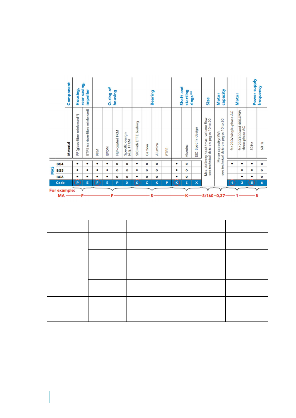
4.4 Type codes and materials
The type code on the nameplate informs you about the pump materials in contact with
fluid.
Overview of available materials being in contact with fluid:
Component Symbol Material Temperature
All components
in contact with
fluid
PP polypropylene 0 to 70°C
ETFE ethylene tetrafluoride ethylene -20 to +100°C
PTFE polytetrafluoroethylene -20 to +100°C
CFR-PTFE carbon fibre reinforced
polytetrafluoroethylene -20 to +100°C
PPS
polyphenylene sulphide
-
20
to +100°C
SIC silicon carbide -20 to +100°C
Alumina aluminum oxide ceramic (99.7%) -20 to +100°C
Seals
EPDM ethylene-propylene-diene rubber -20 to +100°C
FKM fluorinated rubber -20 to +100°C
FEP FEP-coated FKM -20 to +100°C

Centrifugal
pump
MAGSON
13
Issue
201
9
-
0
1
NOTE
Pump housings made of PP are of dark blue colour.
Pump housings made of ETFE are of black colour and marked with a yellow
sticker.
WARNING
Danger of chemical non-resistance of components
#Make sure that the materials used for making the pump are resistant to the fluid(s) delivered.
#Chemical non-resistance may result in leakage of fluid.
#Potential danger to the environment and health.
#In case of doubt, please contact the pump’s manufacturer.
NOTE
For the chemical resistance of materials, please request the material resistance list of the pump’s
manufacturer.
ETFE

14
4.5 Structure of MAGSON MAS
Abb. 1: Structure of MAS BG 5
1 Pump casing 2 Shaft mounting
3 Impeller magnet 4 Casing-O-Ring
5 Rear casing with shaft 6 Mounting flange
7 Bracket with base 8 Outer magnet
9 Motor 10 Lose flange
11 Filling plug 12 Drain plug
Picture shows a MAS BG 5. Other sizes may differ,
please refer spare part drawing within appendix
Centrifugal
pump
MAGSON
15
Issue
201
9
-
0
1
5. Transportandtemporarystorage
5.1 Safety instruction
WARNING
Danger of getting jammed or bruised during transport of the pump
#Make sure to use lifting devices suitable to the weight of the pump.
#Do not remove the lifting device before you have put down the pump safely.
5.2 Transport
1. Unpack the pump or unit upon receipt and check it for damage in transit.
2. In case of damage in transit, make sure to have the carrier draw up and sign the
damage report document.
3. Make sure that the information of the nameplate corresponds with the specifications
and dimensions of the purchase order.
4. The packaging material has to be disposed of according to local regulations.
5.3 Temporary storage
The pump must only be stored at a dry place free of frost. When storing the pump,
protect it against any contaminants getting in.
6. Installation
6.1 Safety precautions
WARNING
Danger of getting jammed or bruised during installation of the pump
#If necessary, use lifting and holding devices suitable to the size and weight of the pump.
#Make sure that all installation work is done by competent and qualified personnel only.
WARNING
Danger of being hit by falling components
#If necessary, use lifting and holding devices suitable to the size and weight of the pump.
#Make sure that all installation work is done by competent and qualified personnel only.
6.2 Installation requirements
Install the pump at a place that allows you easy access at any time. The limit values of
Ambient temperature is as follows: 0 to +40°C for pumps of PP;
-20 to +40°C for pumps of ETFE.
16
6.3 Installation
1.
Install
the pump in a horizontal
position. For any other installation
position, please contact the
manufacturer.
2. Remove all covers and caps from
the flanges before installing the
pump.
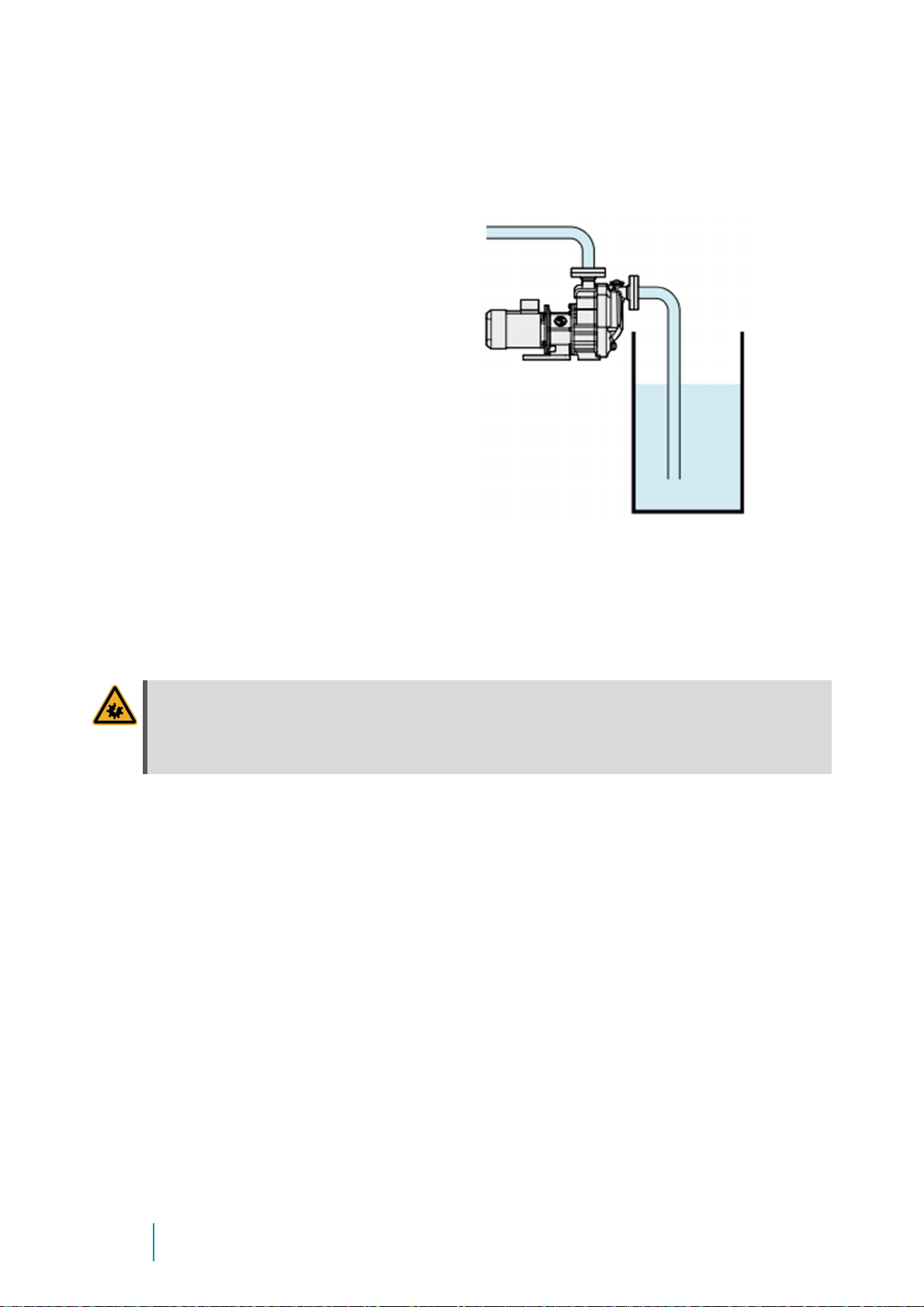
3. The Pump is self-priming. Therefore
it can be placed above liquid level.
4. Max. suction height is 5 mWc
(Water @ 20°C)!
Maximum suction height depends on the fluid to be handled. It may change due to:
#Friction losses in suction pipe
#Higher temperature of the fluid
#Higher density and/or viscosity
#Lower boiling temperature
WARNING
Make sure all bolting’s at suction pipe are vacuum tight!
In case of leaky suction pipe the suction capacity of the pump can be reduced or pump
fails!
Make sure that the pump does not draw in impurities when priming.
6.3.1 Hose and pipe lines
5. All pipe line diameters should be sufficiently large. The speed within the suction pipe
should be between 1 and 2m/s; speed within the discharge pipe should not exceed
3m/s. Pipe diameters have to be at least the size of the suction and discharge ports.
6. All suction and discharge pipes to the pump housing should be free of tensile stress.
7. If necessary, install expansion joints at the pipes to compensate excessive tension due
to the pipe’s thermal expansion.
8. Avoid bending radii of less than 1.5 times the nominal pipe size.
9. Also avoid sharp changes in diameters within the piping.

Centrifugal
pump
MAGSON
17
Issue
201
9
-
0
1
6.3.2 Suction line
ATTENTION
Risk of damaging the pump by cavitation
When installing the suction line, make sure to meet the NSPH value given in the æAppendix page 32 foll.. If
the NPSH falls below this value, there will be cavitation resulting in running noise, drumming and vibration of
the pump.
We do not provide warranty for any damage to the pump caused by cavitation!
10. The suction pipe or hose should be made of a material that will not deform or distort
by vacuum or higher temperatures.
The suction line also should be as short as possible, its installation preventing any gas
accumulation.
11. When dimensioning pipelines, fittings etc., make sure to keep the flow resistances as
low as possible.
12. Provide for a straight steadying section of at least 5 times the nominal diameter
before the suction port.
13. Suction lines have to be vacuum-sealed because penetrating air causes malfunction
and may result in damage to the pump.
14. Make sure that the flow rate in the suction line installed does not exceed 1m/s.
15. Protect the pump against dry-running by installing adequate equipment (optionally
available).
16. For easy installation and removal of the pump, a shut-off valve (but no diaphragm
valve) should be built into the suction line.
NOTE
Do not use the shut-off valve of the suction line to adjust the delivery rate!
6.3.3 Discharge line
Standard flow rate of the discharge line is 3m/s.
Discharge pipe should go straight upwards (approx. 500mm) to avoid liquid losses during
suction procedure.
We recommend installing a control element to adjust the flow rate of the discharge line.
ATTENTION
Damaging of the pump housing by pressure jerks
Do not install any quick-acting stop valves to the pipelines!
To measure working conditions, you better install a manometer between the discharge
port of the pump and the throttle valve as well as a volume flow meter, if necessary.

18
6.3.4 Flange or threaded connections
MAGSON MAS pumps of types BG4 to BG6 are
equipped with slip-on flanges as standard features.
The rotating flange allows you to easily connect the
pump without considering the angular position of the
mating flange.
Do not use hard material to seal the flange but
appropriate elastomer seals.
Replacin
g a flange by a threaded
adapter
Alternatively you can use an insert fitting
and spigot nut to connect the pump.
To do so, you have to replace the screwed
flange by the attached threaded adapter as
follows:
1. Take the slip-on flange off the flange
fixture using a rubber mallet.
2. Use a strap wrench to unscrew the
flange fixture. Take the O-ring off the
fixture and put it into the (inner thread)
of the threaded adapter.
Centrifugal
pump
MAGSON
19
Issue
201
9
-
0
1
3. Screw the threaded adapter to the
pump housing using the strap wrench.
Make sure that the O-ring fits exactly
into the groove of the inner thread.
6.3.5 Electrical connection
NOTE
Qualified personnel only are allowed to connect the pump to the electrical mains.
All electrical connections and the installation of additional protection devices has to be done in accordance
with the regulations of your local power supplier and the VDE Association of German Electrical Engineers.
Before working on the terminal box of the pump, the power supply must have been cut
off for at least 5 minutes.
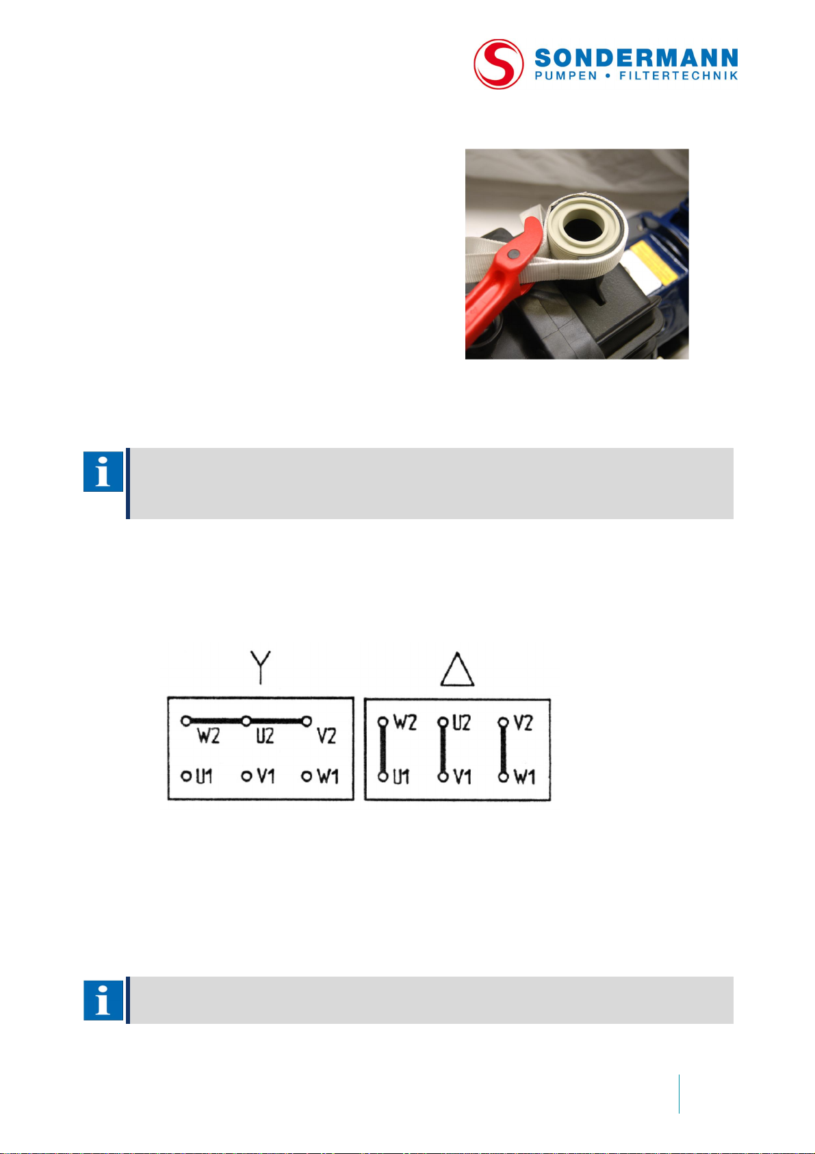
17. Make sure that the power supply available corresponds to the data of the nameplate.
18. Connect the motor according to the following schematic attached to the terminal box:
19. As standard features, all three-phase AC motors have PTC resistors to monitor the
winding temperature. To operate the pump with frequency converter, also connect
the PTC resistors.
20. All AC motors have a thermal sensor as standard feature which also has to be
connected.
21. Do not operate any AC motor without circuit-breaker!
NOTE
Please ask the manufacturer for additional motor protection devices.
20
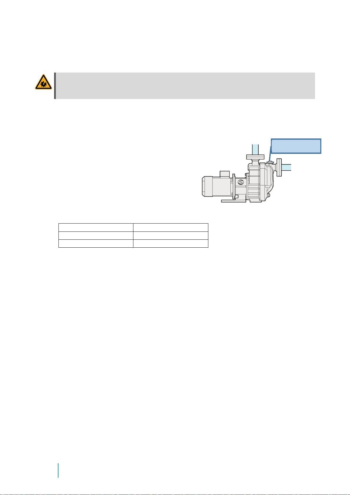
6.3.6 Controlling the direction of rotation
ATTENTION
Dry-running will damage the pump
Do not check the direction of rotation when there is no fluid in the pump!
1. Mind the direction of rotation indicated by an arrow on the pump. Before verifying it
after the installation, fill the pump housing and suction line with water or fluid (refer
item 2).
2.
Detach filling
plug at pump casing a
n
d
fill
fluid into the integrated priming tank.
Attach filling plug properly afterwards.
Dry run of pump without fluid within
integrated priming tank has to be avoided!
Filling amount
:
MAS BG
-
4 13/115
2,7
Liter
MAS BG
-
5 17/230
2,7
Liter
MAS BG
-
6 27/470
3,6
Liter
3. Then switch on and immediately off the motor to check the direction of rotation.
To check whether the direction of rotation corresponds to the direction indicated by
the arrow, push a piece of soft material like paper or cable tie into the slots of the fan
cowl.
4. If necessary, exchange 2 phases at the terminal box to reverse the direction of
rotation.
Fillingplug
This manual suits for next models
3
Table of contents
Other Sondermann Water Pump manuals


Popular Water Pump manuals by other brands

Lincoln
Lincoln HTL 101 user manual

Brinkmann
Brinkmann SFT1554-C operating instructions

ARO
ARO PD10E Series Operator's manual

Becker
Becker U 5.101 operating instructions

Sulzer
Sulzer AHLSTAR 2.15 Series Installation,operation and maintenance instruction

LEYBOLD
LEYBOLD SOGEVAC SV470 B AIR Original operating instructions


Granudos
Granudos 10-S4 operating instructions

GORMAN-RUPP PUMPS
GORMAN-RUPP PUMPS T8A61S-B Installation, operation and maintenance manual

Agilent Technologies
Agilent Technologies X3502-64170 user manual

Graco
Graco Series A Assembly

Danfoss
Danfoss PAH 20 Installation, operation and maintenance manual

LEYBOLD
LEYBOLD TRIVAC S 16 B operating instructions