Sonel UV-260 Corona Camera User manual

UV-260 –USER MANUAL
2

USER MANUAL
CORONA CAMERA
UV-260
SONEL S.A.
Wokulskiego 11
58-100 Świdnica
Version 1.03 17.12.2019

UV-260 –USER MANUAL
2
The UV-260 Corona Camera detects and precisely locates corona discharge emanating from
high-voltage devices. It will help locate and determine the power of a discharge by capturing UV
radiation released during corona discharge and provides a reliable method for the technical
assessment of the operation and behaviour of high-voltage equipment.
When corona discharges are detected, the camera will overlay images of the corona on the
visible image. Images are displayed in real time on the camera's screen. Under user control the
images may be also recorded as a video file. Images may be stopped and saved as a still image.
Recorded images and videos arestored on a removable SDcard in a format compatible with viewing
on personal computers.
Main features of UV-260:
high UV-sensitivity, user adjustable
automatic or manual focus adjustment for real image and UV image
combining of visible-spectrum images and UV-spectrum images
automatic reduction of noise and interference
5.7" TFT touch-screen
designed to operate in sunlight
UV discharge detection alarm
built-in GPS system for recording location
precisely locates UV discharge sources
UV discharges and visible images recorded as photos or videos in common PC format
report generator program included

UV-260 –USER MANUAL
3
CONTENTS
1. Introduction..................................................................................................5
2. Safety ............................................................................................................ 5
3. Principle of Operation ................................................................................. 6
3.1. Electromagnetic radiation: visible, infra-red, ultraviolet.........................................6
3.2. Mechanism of Corona Discharge..........................................................................7
3.3. Why Corona Discharge?.......................................................................................8
3.4. Detection of Corona Discharge.............................................................................8
4. Preparing the Camera for Operation ....................................................... 10
4.1. External design of the camera ............................................................................10
4.2. Mounting on a Tripod..........................................................................................11
4.3. Moving and Holding the Camera.........................................................................12
5. Ports and Buttons......................................................................................13
5.1. External Ports .....................................................................................................13
5.2. Layout and functions of buttons..........................................................................14
5.2.1. Navigation buttons...................................................................................................14
5.2.2. Operating mode buttons..........................................................................................15
5.2.3. Control of power supply / charging and alarm - corona discharge indicator..............15
6. Operation and Battery Charging ..............................................................15
6.1. Inserting the Battery............................................................................................15
6.2. Charging the Battery...........................................................................................16
6.3. Guidelines for Using the Battery .........................................................................16
7. Working with UV-260 Camera...................................................................17
7.1. Operation of the buttons .....................................................................................18
7.1.1. Recording a Video...................................................................................................18
7.1.2. Recording a Static image.........................................................................................18
7.1.3. Switching the Image Mode ......................................................................................18
7.1.4. "Freezing" Displayed Image.....................................................................................18
7.1.5. Changing the Focus Mode.......................................................................................18
7.1.6. Gain Adjustment......................................................................................................19
7.1.7. Zoom.......................................................................................................................19
7.1.8. Manual Focus..........................................................................................................19
7.1.9. Zooming In..............................................................................................................19
7.1.10. Playing a Voice Note...............................................................................................19
7.1.11. Zooming UV+ Image.............................................................................................19
7.2. Operating the Menu ............................................................................................20
7.2.1. Main menu ..............................................................................................................20
7.2.2. Image Settings ........................................................................................................21
7.2.3. Video.......................................................................................................................22
7.2.4. Image......................................................................................................................22
7.2.5. System....................................................................................................................22
7.2.6. Sub-menu "System Settings"...................................................................................23
8. "Sonel UV Analyse" software...................................................................24
8.1. System Requirements.........................................................................................24
8.2. Software Operation.............................................................................................24

UV-260 –USER MANUAL
4
8.2.1. Starting-up Software................................................................................................24
8.3. Software Operation.............................................................................................25
8.3.1. Main Function Area .................................................................................................25
8.3.2. Toolbar....................................................................................................................26
8.3.3. Template Selection..................................................................................................26
8.3.4. Appearance Setting & Font Setting..........................................................................28
8.3.5. Cancel.....................................................................................................................28
8.3.6. Line.........................................................................................................................28
8.3.7. Edit Box...................................................................................................................28
8.3.8. Add Pictures............................................................................................................28
8.3.9. Image Setup............................................................................................................30
8.3.10. Audio Play...............................................................................................................31
8.3.11. List box....................................................................................................................32
8.3.12. Vertical list...............................................................................................................33
8.3.13. Line Analysis...........................................................................................................33
8.3.14. Histogram................................................................................................................34
8.3.15. Page Attribute..........................................................................................................35
8.3.16. Video Transmission.................................................................................................35
10.Other Information ......................................................................................38
10.1.Cleaning and Maintenance .................................................................................38
10.2.Storage ...............................................................................................................38
10.3.Dismantling and Disposal....................................................................................38
10.4.Transport.............................................................................................................38
11.Technical specifications ...........................................................................39
12.Accessories................................................................................................40
13.Manufacturer ..............................................................................................41

UV-260 –USER MANUAL
5
1. Introduction
Thank you for choosing the UV-260 corona camera. The UV-260 Corona Camera is a high-
quality imaging device that is easy and safe to use. Carefully read this manual before the first use to
prevent errors and problems while operating the device.
This manual contains three types of warnings that describe the possible risks both for the user
and the device. Information with a "WARNING" describe situations which may endanger the user's
life or health when instructions are not followed. "CAUTION!" describes of a situation which may
result in damage to the device when instructions are not followed. Indication of possible problems is
preceded by "Note".
The device has been designed, developed, and manufactured in accordance with ISO 9001
quality systems. Sonel reserves the right to change device specifications without prior notice.
Copyright of this manual and software are the property of Sonel.
2. Safety
WARNING
Do not attempt to open the device as none of the components can be repaired or
calibrated by the user. Any maintenance activities may be carried out only by
authorized service personnel.
NOTE
Do not drop, or subject the camera to rough handling or shocks during operation, handling,
and transportation.
NOTE
Avoid pointing the lens directly at the sun or objects that emit very high temperature as this
may cause damage. Take care to observe this precaution and make sure the camera is not
pointed at the sun when switching the device ON/OFF.
NOTE
Never touch the lens. Dust accumulated on the lens may be removed only by using special
tools or compressed clean air.
The camera should be stored in cool, dry place, away from sources of strong electromagnetic
fields. When the camera is not used for a long time remove the batteries.
During operation the camera should be securely fastened to minimize shake and vibrations that
will adversely affect the accuracy.
WARNING
Do not use the camera if it's enclosure is damaged in any way as this is a safety threat to
the user.
UV-260 –USER MANUAL
6
When working with the device observe the technical conditions specified in this manual.
Damage to the camera, resulting from improper use, alteration, and obvious negligence are not
covered by the warrantee.
3. Principle of Operation
Corona discharge is one of three types of partial discharge. Partial discharge is the breakdown
of an insulator (or dielectric) caused by high voltage stress, usually in a portion or area between two
conductors that does not result in a complete short circuit. In addition to corona discharge there are
surface discharges, due to contaminated insulator surfaces, and internal discharges caused by the
degradation of the insulation that results in voids or pockets that provides paths for partial discharge
to develop. These situations are progressive in that discharge currents exacerbate further
degradation ultimately leading to complete insulator failure. Corona-type partial discharge is the
localized ionization of a gaseous insulationsystem, suchas air, usuallyconfined to a limited distance
between two conductors. Corona can occur within voids in insulators as well as at the surfaces where
conductors and insulators meet.
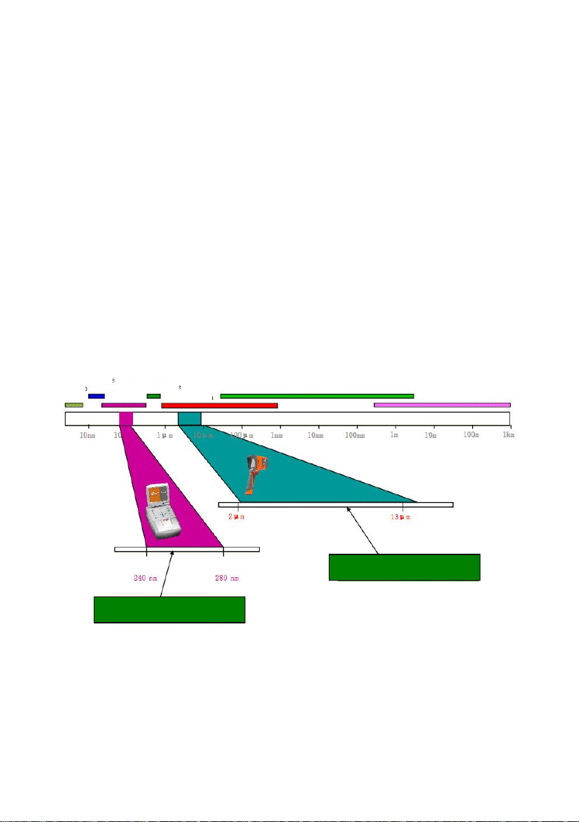
3.1. Electromagnetic radiation: visible, infra-red, ultraviolet
Individual types of electromagnetic radiation have wavelengths as shown in Figure 1.
Figure 1: Electromagnetic waves of different lengths.
Gamma Rays
X-Rays
,
Ultraviolet
Visible radiation
Infrared
Microwaves
Radio waves
Thermal camera
UV camera
,

UV-260 –USER MANUAL
7
3.2. Mechanism of Corona Discharge
Corona discharge is a current flow, usually in a gas such as air, from a discharge electrode under
high voltage conditions that causes ionization of the surrounding gas. Ionization is the separation of
electrons from the gas atoms. If sufficiently ionized the gas can create a plasma; ionized matter
containing electrically charged particles, around the electrode. The ions in the plasma create an
electrical path that carry the electrons to lower potential.
If the discharge electrode has a sharp or pointed shape, a high-voltage potential gradient is
generated around the point. If the potential gradient is high enough to cause ionization a discharge
will occur. At very high voltage it may be a sparking phenomena, or it may be an arc whereby a
plasma is created that establishes a path of continuous electron flow. Corona accompanies plasma
states but also occurs when ionization levels are not at a full plasma state of high volume electron
flow; i.e. corona emissions can also be initiated a lower level of discharge or electron flow provided
ionization is present.
Most corona discharge is invisible in daylight. Even in total darkness it may be barely visible as
a blue-violet afterglow as most of the radiation generated is in the ultraviolet range and invisible to
human eye. Attempting to observe corona at night is virtually impossible since total darkness cannot
be achieved in urban environments. Other methods of detection attempts to use acoustics to detect
the crackling sounds that can accompany discharges but these methods are unreliable and cannot
precisely locate the source of corona generation. Thus, acoustic-based detection methods are being
replaced with UV-based detectors that are far more effective.
Corona discharges are generated in the electromagnetic spectrum wavelengths in the range
between 200 to 405 nm. Solar radiation contains visible light, infra-red, and ultraviolet radiation. By
using an appropriate filter with wavelength between 240 to 280 nm to suppress UV radiation from
the sun the camera is designed to detect corona even in daylight conditions.
Fig. 2: The spectrum of corona discharge
Range filtered by the
camera
Solar radiation spectrum
Visible light
Ultraviolet
Wavelength (nm)

UV-260 –USER MANUAL
8
Depending on the polarity of the discharge electrode, the corona discharge may be positive or
negative. In either case of negative or positive discharges photons are the main source of radiation.
When the gas atoms are ionized their electrons are "excited" and kicked up to a higher energy states.
Photons are released bythe ionized atoms as they return to lower energy states. The corona camera
shows a display scale in "UV photons" to provide an indication of the volume of photons generated.
Positive discharge is said to be homogeneous; the majority of charges are concentrated close to
the electrode so the discharge area is well defined and easily located. Negative discharge at the
same voltage may be weaker and more difficult to locate since the energy is more spread out over a
wider area.
3.3. Why Corona Discharge?
Corona discharges are a loss of energy. Unwanted corona discharge also cause a variety of
problems such as radio interference i.e. poor reception of radio signals due to noise coming from
nearby high voltage power lines. The most adverse effect of corona discharges is the impact on the
condition of insulation elements resulting in "wear and tear" over time; i.e. the gradual deterioration
of the insulator and it's ability of the to provide a dielectric barrier. Even the presence of small
discharges cause adverse effects. The discharge current flow generates corrosive substances that
contribute to the breakdown of insulators creating voids and cracks. These enable the ingress of
moisture to internal components, further accelerating degradation.
If left unchecked bad insulation can bring about the failure of entire power transmissionsystems.
Since high voltage transmission systems are the main arteries of power that serve millions of
consumers, any disruption to the electrical grid's transmission systems is both economically and
socially disastrous. Therefore, it is prudent to detect the early stages of corona discharges to catch
incipient problems before they develop and lead to permanent damage that results in costly repairs
and wide-area blackouts. Locating corona discharges is a sensible cautionary preventative
maintenance measure, similar to infra-red thermal camera inspection methods, to discover potential
problems before they arise.
3.4. Detection of Corona Discharge
The UV-260 detects and locates corona discharges by detecting their UV radiation. The level of
discharge is quantified and the number of discharges in a certain time-frame is represented
graphically by the 'UV image'. The camera operates in both the visible light and the UV spectrums.
By pointing the camera at a desired object and viewing it as a real image, in the same way as any
video camera, any detected UV emissions are precisely overlaid on the visible image. The UV
radiation is represented as a white, blue, or red video image rendered against the visible image. This
provides an accurate method of locating the source of emissions and therefore the point of
degradation that would otherwise be difficult to distinguish in high voltage transmission systems, or
complex substations with multiple conductors and equipment. Inspection for corona with the UV-260
is inherently safe when high voltage systems are live since inspection is performed from a distance.

UV-260 –USER MANUAL
9
Fig. 3, 4. Corona discharge in laboratory conditions.
Fig. 5-8. Corona discharge in real power grids.

UV-260 –USER MANUAL
10
Fig. 9, 10. Corona discharge and its effects.
4. Preparing the Camera for Operation
4.1. External design of the camera
The UV-260 is compact, simple, and ergonomic camera to use. It may be operated on a tripod
or used as a hand-held tool. Its features are illustrated in Figures 11 and 12.
Fig. 11. Parts of Camera UV-260.

UV-260 –USER MANUAL
11
4.2. Mounting on a Tripod
For long periods of observation mounting the camera on a tripod is recommended to eliminate
shake and vibration (Fig. 12). A standard, threaded tripod mount is provided at the bottom of the
camera.
Note. Firmly attach the camera to the tripod to prevent accidental damage.
Fig. 12 UV-260 mounted on a tripod.

UV-260 –USER MANUAL
12
4.3. Moving and Holding the Camera
The UV-260 may be used as a hand-held device, or the operator can use the more convenient
strap to ease fatigue from holding for long periods. The strap also frees the operator's hands during
operation (Fig. 13, 14).
CAUTION!
To prevent dropping and damaging the camera when fastening and unfastening of the strap
place the camera on a table or other surface, and fasten or unfasten the strap in the upright
position (fig. 13). Test the strap is securely fastened before operation.
Fig. 13. Fixing strap to the holders.
The camera when suspended on thestrap allows theoperator to easilyuse the keyboard (Figure 14).
Fig. 14. The camera securely mounted on the strap.

UV-260 –USER MANUAL
13
5. Ports and Buttons
5.1. External Ports
Camera interfaces, charging indicator, power adapter input, SD card slot, and the battery
compartment are located under the cover on the side of the camera (Fig. 15).
Fig. 15. Arrangement of ports under the cover.
Video output may operate in PAL or NTSC system.
The SD card must be formatted in FAT32.
When recording voice notes speak closely into the microphone. Plug the microphone headset
into the audio input located under the cover.
CAUTION!
When inserting the battery pay attention to the correct polarity.
Voltage connected to power input cannot exceed 12V.

UV-260 –USER MANUAL
14
5.2. Layout and functions of buttons
Fig. 16. Arrangement of the control panel buttons.
5.2.1. Navigation buttons
Buttons for menu operation and image functions:
- Up,
- Down,
- Left,
- Right,
- confirm,
- exit without confirmation.
In addition to menu navigation, functions of the buttons are as follows:
- "freezing" the displayed image,
- switching into the focus adjustment mode,
- playing a voice note
- zooming in combined (mixed) image mode (real image +UV).

UV-260 –USER MANUAL
15
5.2.2. Operating mode buttons
- image display mode switch, repeated pressing of the button causes toggling of the
following modes: UV image only - visible image mode - mixed mode (UV plus visible image)
- saving the still image,
- video recording,
and - manual focus adjustment,
and - zoom in/out
5.2.3. Control of power supply / charging and alarm - corona discharge
indicator
- switching on / off,
- power indicator,
- corona discharge indicator.
6. Operation and Battery Charging
The UV-260 is powered by a dedicated lithium-ion rechargeable battery, which should be
charged only with the charger included with the camera.Any other batteries, even of thesame shape,
and other chargers may damage the camera and present a danger to the user.
The battery may be also charged by the camera via an AC adapter or a car adapter (12V) - both
included with the camera.
When battery level is low a message will be displayed on the screen indicating the need for
recharging.
6.1. Inserting the Battery
Insert the battery into the battery compartment located under the cover for inputs and battery
compartment (Fig. 15).

UV-260 –USER MANUAL
16
6.2. Charging the Battery
The batterymay be charged using the external charger or by connecting the AC adapter with the
battery inserted into the camera using the power socket located slot under the battery compartment
cover 4 .
The charging indicator light is red during charging. When charging is completed the charging
indicator light is green.
WARNING.
At high temperatures do not turn on the camera while charging the battery, as it may
decrease battery life, or even cause fire.
6.3. Guidelines for Using the Battery
Charge the batteries in a dry indoor location. Do not charge the batteries outside, especially
during rain, etc.
WARNING.
Do not short-circuit the battery, and avoid accidental short circuits bypreventing the
battery terminals from coming into contact with other metal, or loose objects.
The battery should be stored at a temperature not exceeding 60°C / 140°F.
When charging is finished disconnect the external power supply adapter. When replacing the
battery disconnect the power supply adapterfirst. Insert the battery intothe camera, and thenconnect
the AC adapter. Do not use non-original batteries and chargers.

UV-260 –USER MANUAL
17
7. Working with UV-260 Camera
In order to switch the camera on press and hold button for approx. 2 seconds. The camera
starts by performing auto-tests for about 25 seconds, then it switches on the operating screen (Figure
17).
Fig. 17. Working screen in mixed image mode - detecting corona discharges.
The screen, in addition to the image in the selected mode (UV, visible, mixed), displays the
following information:
- current date and time,
- GPS coordinates of the measurement location
- signal gain level
- battery charge status
- focus adjustment mode (auto or manual),
- image mode indicator: mixed UV+ , visible image VIS , or UV image only: UV
The white frame is the effective area for photon counting, where discharges are recorded and
the amount of UV photons indicated. The operator may select 3 frame sizes - large, medium, and
small.
Date, time
GPS coordinates
Frame - area for
counting discharges
Discharge
Gain
Amount of UV
photons
Focus mode
Battery indicator
Screen Mode (VIS,
UV, UV+)
UV-260 –USER MANUAL
18
7.1. Operation of the buttons
Description of the operations available by pressing buttons in the working screen mode.
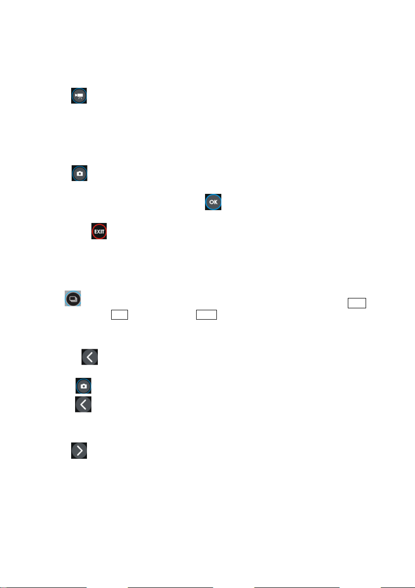
7.1.1. Recording a Video
Press to start recording a video and saving it on a SD card. This allows real-time recording
of images that are displayed on the screen. When recording video you may add a voice note using
the headset connected the audio input. Video files are recorded in "avi" format that can be played in
the camera or on a PC.
7.1.2. Recording a Static image
Press to save the image displayed on the screen into the SD card.
When the image is recorded the screen displays the message "record a voice note". At this point
you can record 20-second voice memo, press to start voice recording (with a microphone
headset connected to the audio input). The image is saved and the camera returns to the real-time
mode. Or press to save the image without recording a voice note.
Note. For the best quality it is recommended to 'freeze' the image on the screen before saving it
- see below.
7.1.3. Switching the Image Mode
Use button to toggle and switch between the following modes: Visual image only VIS , UV
discharge mode only ( UV ) and Mixed mode ( UV+ ).
7.1.4. "Freezing" Displayed Image
Pressing "freezes" the image allowing you to make a decision about saving it into memory.
At this point:
- press to save image to the SD card and return to detection mode in real-time
- press again to return to the detection mode (real-time) without saving the image.
7.1.5. Changing the Focus Mode
Press to change the focus mode from manual to automatic and vice versa. By default, the
camera upon powering on is set to auto focus mode. In case of a complex image with many objects
at different distances the focus may not be set automatically to the desired object. If so the operator
can switch to the manual focus mode.
Other manuals for UV-260 Corona Camera
2
Table of contents
Other Sonel Digital Camera manuals


