Sonic 350 User manual

L10029 REV C ECO1653
Sonic Air Systems, Inc.
Phone: (714) 255-0124
1050 Beacon Street
Fax: (714) 255-8366
Brea, California 92821
www.sonicairsystems.com
Saving Energy Worldwide
...one PSI at a timeTM
©Copyright 2010-Sonic Air Systems Inc.
INSTALLATION AND OPERATION
MANUAL
SONIC 350 BLOWER

www.sonicairsystems.com
©Copyright 2010-Sonic Air Systems Inc. Page 2of 26
Table of Contents
SAFETY PROCEDURES......................................................................................................................3
Electrical...................................................................................................................... 3
Mechanical.................................................................................................................. 3
EQUIPMENT INSPECTION AND INSTALLATION..............................................................................4
Equipment Inspection.................................................................................................. 5
Identification of Blower and Motor............................................................................... 5
Blower Nameplate....................................................................................................... 6
Lifting and Handling..................................................................................................... 8
Blower Location........................................................................................................... 9
BLOWER PERFORMANCE & INTERFACES......................................................................................4
The Blower Features:.................................................................................................. 4
Air Filters..................................................................................................................... 4
Airknife Systems.......................................................................................................... 4
Blower Performance.................................................................................................... 4
Blower Cavitation (Surging)......................................................................................... 5
Blower Interfaces......................................................................................................... 5
MOTOR WIRING AND START-UP ....................................................................................................10
BELT INSTALLATION AND TENSION ADJUSTMENT ....................................................................11
1. Belt and Sprockets Combinations ......................................................................... 11
2. Belt Installation...................................................................................................... 12
3. Sprocket Alignment............................................................................................... 14
4. Belt Tension Adjustment ....................................................................................... 19
SONIC 350 ASSEMBLY – 40&50 HP Motors ...................................................................................22
Table 7 - PARTS LIST AND TORQUE SPECIFICATION ..................................................................23
GENERAL MAINTENANCE...............................................................................................................25
TROUBLE SHOOTING ......................................................................................................................26

www.sonicairsystems.com
©Copyright 2010-Sonic Air Systems Inc. Page 3of 26
1. SAFETY PROCEDURES
1.1. Electrical
Always use qualified electrical and mechanical personnel for installation and maintenance of Sonic Air
Blowers.
No work should be performed on a Sonic Air Blower until the power has been turned off and the isolation
device has been locked. Disconnect the electrical power at the motor starter, fuse box, or circuit breaker
before working on the blower / motor. Double check to be sure that the power is off and that it can not be
turned on while personnel are working on the blower / motor assembly.
Use proper electrical installation wiring and controls consistent with local and national electrical codes. A
lockable isolation switch should be provided.
Note: It is recommended to use a soft starter for the motor to prevent belt teeth premature
deterioration.
Refer to motor nameplate data for the proper power supply requirements. Make sure the
junction box connections are tight and well insulated to prevent shorts and to assure
maximum protection against moisture.
Be sure the motor is electrically grounded and the mounting bolts are secure.
1.2. Mechanical
Never run the Sonic blower without the belt guard installed.
Never run the Sonic blower with the outlet open to atmosphere as this can cause motor overload.
Never run the Sonic blower with the inlet open to atmosphere. Always connect the Sonic Inlet Filter to the
blower inlet to prevent personal injury and damage to the blower.
Keep tools, clothing and hands away from rotating or moving parts while the unit is running.
Use safety glasses when working around the blower/motor and/or air-knife assembly while it is running.
Always use proper lifting techniques and equipment.
Observe good safety habits at all times and use care to avoid personal injury or damage to the equipment.

www.sonicairsystems.com
©Copyright 2010-Sonic Air Systems Inc. Page 4of 26
2. BLOWER PERFORMANCE & INTERFACES
2.1. Sonic 350 Centrifugal Blower
The Sonic 350 is a dual stage centrifugal blower. With speeds of 3500 up to 4200 RPM, the blower requires
a driving power of a 40 to 50 HP motor depending on the amount of airflow demand. The volumetric
airflow of the blower ranges between 650 to 3500 SCFM at a discharge pressure ranging between 15 to 100
in. of water. The blower drive consists of motor sprocket, blower sprocket and belt. The procedure for belt
tension adjustment is described in Section “Belt Installation and Tension Adjustment”.
Of utmost importance in the proper operation of the blower, is the correct face alignment of the blower and
motor sprockets. This alignment was performed at Sonic and should not have to be modified. The procedure
for sprocket alignment is described in Section “Belt Installation and Tension Adjustment”.
Note: The Sonic 350 is not designed for series (two stage) operation; consult Sonic engineering for
high pressure or vacuum requirements.
2.2. The Blower Features:
Belt replacement in less than 10 minutes
Belt tension adjusted with a simple jack
screw mechanism
4 different blower mounting positions
Heat of compression temperature rise up
to 75
°
F assists in airknife drying.
Permanent grease lubricated bearings for
continuous duty
Dual-stage impeller in series
configuration
Steel construction
Bracket interface for 40 and 50 HP
NEMA and IEC frames
At pressures of 3.5 psi, airknife
velocities can reach 35,000 FPM
2.3. Air Filters
For most applications, Sonic filter-silencer assemblies are standard. The filter element is rated to 10 microns
and is offered in paper & polyester elements. Paper is low cost and is best suited where frequent cleaning is not
required. When heavy dirt loads or moisture is present, polyester elements are best, as they can be cleaned and
reused 5-6 times. The vacuum gauge reads normal (green) until the dirt load increases and the red zone reading
indicates that filter cleaning or replacement is required. Consult Sonic for HEPA Filters with 0.3 micron rating.
2.4. Airknife Systems
Sonic XE Airknife Systems are designed for each application and must be properly matched to the appropriate
Sonic Blower. When properly installed and operated, the electrical load on the motor (amp draw) is intended to
be at full load. Any adjustment of the Airknife slots should only be done with the supervision of Sonic Air or
our authorized distributor/representative.
2.5. Blower Performance
The Sonic 350 is a dual stage centrifugal blower whose performance is in accordance with fan engineering
laws. Horsepower demand increases in proportion to increased volumetric airflow (i.e. motor amperage

www.sonicairsystems.com
©Copyright 2010-Sonic Air Systems Inc. Page 5of 26
draw increases). As air volume decreases (valves close, filters clog), the amp draw decreases. Always check
a fully installed system to ensure the motor is not overloaded.
2.6. Blower Cavitation (Surging)
The Sonic 350 blower operates properly in the range of flows between 650 and 3500 SCFM without
overheating or surging. At flows lower than 650 SCFM the surging is mild however if the blower is run
repeatedly at these low settings, the life of the bearings will decrease.
2.7. Blower Interfaces
Blower Inlet – The blower inlet must be coupled to an air inlet filter-silencer or an inlet air safety screen. A
Sonic Air inlet filter-silencer should be used in every application in order to protect the blower internal
components, to provide the level of air filtration imposed by the application and to reduce the inherent noise
which accompanies the flow at the inlet of a turbomachine. Sonic standard filters are rated at 10 microns
and are available with paper or polyester elements. Inlet air temperatures must not exceed 125˚F (52˚C). If
the blower is in an enclosed space and the inlet air is piped from another area, make sure that the ambient
temperature around the blower/motor does not exceed 110˚F (43˚C). When air is re -circulated from an
Airknife zone, In-Line filters and Water Separators must be used.
Blower Outlet – The blower outlet must always be coupled to a discharge silencer or system piping and
directed away from personnel. Discharged air should be silenced to levels required by occupational
safety and health standards. In order to minimize the pressure drop and noise transmission, Sonic
recommends the use of smooth bore tubing (hard plastic or metal)
Flex Hose and Sleeves – Flex hose can have high-pressure drop and should only be used when
absolutely necessary. Flex hose should be able to handle pressures of 10 PSIG at 200ºF (93ºC). Flex
hose can be used for connecting misaligned piping and bend radii that do not match standard elbows. Be
aware that flex hose can collapse inside and should be inspected if flow problems occur. Short rubber
sleeves with T-bolt clamps are standard for blower and piping connections.
Butterfly Valves – Sonic Butterfly Valves are designed to regulate system air flow during normal
operation and to allow air leakage in the closed position to prevent blower surging.
3. EQUIPMENT INSPECTION AND INSTALLATION
3.1. Equipment Inspection
Upon receipt of the Sonic Air Centrifugal Blower, make sure that all components listed on the packing slip
are present. Check to see that the serial number stamped on the blower housing nameplate matches the
packing slip. Inspect the blower to ensure that it is mounted with the correct outlet position and that the
motor has the correct horsepower rating, voltage and enclosure. If the inspection reveals any shortages,
discrepancies or shipping damage, please call the nearest Sonic Distributor or Sonic Air Systems
immediately to have the problems corrected.
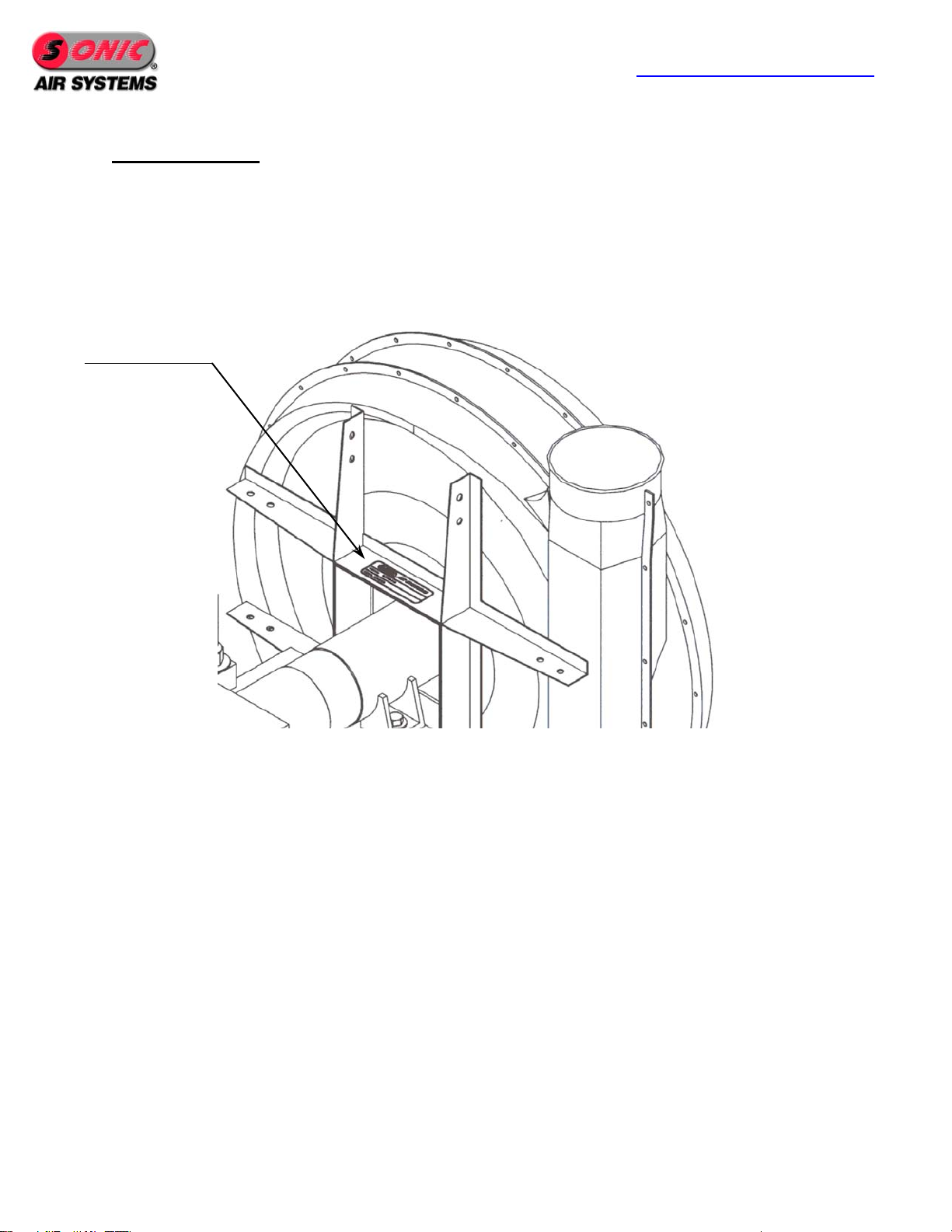
3.2. Identification of Blower and Motor
There are two points of identification:
1) Serial number stamped on the nameplate located on the top horizontal rib on the rear of the blower (see
Fig. 1).

www.sonicairsystems.com
©Copyright 2010-Sonic Air Systems Inc. Page 6of 26
2) Motor manufacturer nameplate on the motor.
Blower Nameplate
Each Sonic Blower has a serial number stamped on the nameplate. Refer to the packing slip and record
blower serial number for future reference, on the line below.
Serial No: _________________________
Fig.1 - Blower Identification
NAMEPLATE

www.sonicairsystems.com
©Copyright 2010-Sonic Air Systems Inc. Page 8of 26
Warning: Blower head position is determined by Sonic Air Systems in agreement with the customer.
Any attempt by the customer to modify the position of the blower head will result in voiding
the factory warranty.
3.3. Lifting and Handling
Due to the weights of the blower / bracket / motor assemblies, they should be lifted with a hoist or forklift.
If lifting the motor independently of the entire assembly it should only be hoisted from the single lifting eye
located on the top-middle of the housing. If the Blower Head Assembly needs replacing it should only be
hoisted using (2) lifting straps placed under the Blower cover and hoisted from above. The Bracket,
Bracket/Motor Assembly or the Bracket/Motor/Blower Assembly should only be lifted with a forklift and
using the specially designed bracket legs (rectangular tubing) (see Fig.5). During the handling process
follow all safety measures in order to prevent personal injury and equipment damage.
Sonic Equipment Weight
Sonic 350 with 40 HP TEFC NEMA Frame 326TS 1050 lb / 521 Kg
Sonic 350 with 50 HP TEFC NEMA Frame 326TS 1150 lb / 521 Kg
Note: Motor weight may vary between different manufacturers
Lifting Leg
Anchor Bolt
Motor Eyelet

www.sonicairsystems.com
©Copyright 2010-Sonic Air Systems Inc. Page 9of 26
3.4. Blower Location
Access Make certain to allow room for proper ventilation and accessibility for belt inspection and
replacement as well as for inlet filter servicing.
Temperature
The blower/motor assembly must be placed in an area that prevents hard freezes or overheating.
Ambient temperature conditions may range from +10˚ F ( -12˚ C) to +110˚ F (43˚ C). The
blower/motor unit is suitable for outdoor locations, but care should be taken to protect the equipment
from temperature extremes, direct exposure to mid day sunshine, rain, snow and dust so as to extend
the service life of the blower and motor.
Moisture and Debris
Sonic 350 Blowers have a high-speed belt drive, close tolerance components and precision bearings.
Do not put the blower in areas where it will be sprayed from a washing / rinsing zone or over-
sprayed by an airknife or where dust, dirt or other debris will attack the drive belt or clog the filter. If
the filter needs cleaning or replacing more than one time each month, the blower or filter should be
moved to a cleaner, drier area. A Sonic acoustical blower enclosure will also provide additional
protection from external influences safe operation. Contact Sonic for additional information.
Wash Down
In factory locations subject to high-pressure water or caustic wash-down cycles, the blower must be
protected or relocated in order to prevent damaging it. Raising the blower 1-2 feet above the wash
zone is generally enough. Wash-down duty motors and corrosive resistant blower coatings are
available to allow full exposure should it be needed.
Vibration
The Sonic 350 blower has a low vibration level and can be bolted to any type of foundation or
framework without transmitting any significant vibration. Sonic Air Systems tests have indicated a
maximum velocity of .400 in/sec, a value much smaller than the maximum allowable velocity of
0.708 in/sec imposed by ISO Standard 10816-I, class II-D for rotating equipment in this blower
category.
Motor Eyelet

www.sonicairsystems.com
©Copyright 2010-Sonic Air Systems Inc. Page 10 of 26
MOTOR WIRING AND START-UP
Note: It is strongly recommended to use a soft starter connected in series with the motor
power supply. Using a soft starter has the benefit of preventing drive belt damage
(destruction of belt teeth in shear) and of eliminating the electric load bursts that can
damage the plant power system.
● Only qualified personnel should perform motor wiring.
● Never run a Sonic centrifugal blower with the discharge open to atmosphere – such a situation leads to
motor overloading and motor damaging.
● The Sonic 350 blower must rotate counter clockwise (CCW) when viewed from the sprocket end or
clockwise (CW) when viewed from the cooling fan end of the motor – see Fig.6 below.
Fig.6 Blower Rotation

www.sonicairsystems.com
©Copyright 2010-Sonic Air Systems Inc. Page 11 of 26
BELT INSTALLATION AND TENSION ADJUSTMENT
1. Belt and Sprockets Combinations
The Sonic 350 blowers are designed to cover the range of rotational speeds from 3500 RPM through 4200
RPM by using a single size sprocket on the blower shaft and 4 different sprocket sizes on the motor shaft.
For any sprocket combination there is only one belt size. To accommodate the different motor shaft sizes
specific to the 30, 40 and 50 HP in the NEMA or IEC specifications, it is necessary to use the proper QD
bushing (tapered bushing). The tables below give all the part number information applicable to the motor
and blower sprockets and QD bushings as well as the drive belt.
Table 1- Drive Belt
Drive Belt Part
Number
Drive Belt Length
[MM]
12708
1750
Table 2 - Blower Sprocket and QD Bushing
Sprocket Part
Number
Sprocket Outside
Diameter [IN]
Sprocket Number of
Teeth
QD Bushing Part
Number
12772
5.2
30
12678
Table 3 - Motor Sprockets and QD Bushings for use with NEMA motors
50HP motor
40HP motor
Sprocket Part
Number
Sprocket
Outside
Diameter [IN]
Sprocket
Number
of Teeth
QD Bushing
Part Number
QD Bushing
Part Number
12775
6.2
36
12674
12674
12774
5.9
34
12673
12673
12773
5.5
32
12673
12673
12772
5.2
30
12673
12673

www.sonicairsystems.com
©Copyright 2010-Sonic Air Systems Inc. Page 12 of 26
2. Belt Removal and Installation
Note: this procedure describes belt installation when motor and blower sprockets are
aligned; for alignment procedure see paragraph 3 below
2.1 Tools required:
1-1/8 in. open wrench (used at jack-screw hex nut)
15/16 in. socket wrench with 6 in. extension (used at sliding bracket hex nuts)
Cross Recessed (Phillips Head) Screwdriver (used at belt guard screws)
Belt Tension Tester Sonic P/N 12817
2.2 Read all safety procedures before starting any of the following steps.
2.3 Remove belt guard by loosening the six cross-recessed head screws holding it to the
structure. Slide the belt guard up and away from the structure (see Fig.7).
2.4 Loosen 1-1/2 turns (do not remove) the four 5/8" hex nuts that are holding the blower
support bracket to the motor (see Fig.8). Due to the various motor sprocket sizes that are used
for any particular application, the center distance of motor / blower sprockets will vary.
There is only one belt size used for all applications and, as a consequence, there will be
various height positions of the blower relative to the motor.
2.5 Loosen the 3/4" hex lock-nut of the jack-screw mechanism (see Fig.9); turn the jack screw
counterclockwise to lower the blower to the proper height that will allow for the belt to easily
wrap around motor and blower sprockets. Make sure there is a good meshing between belt
teeth and sprocket teeth (see Fig.10).
2.6 In order to raise the blower bracket support and tension the belt, rotate the jackscrew
clockwise. Following the procedure described in section 4 below, measure and adjust the belt
tensioning force.
2.7 Tighten the four 5/8” hex nuts, that are holding the blower support bracket to the main
bracket to 88 +/- 12 ft-lbs. Recheck sprocket alignment as described in section 3 and correct
as necessary.
2.8 Tighten the jackscrew locknut.
2.9 Reinstall the belt guard and tighten the six cross-recessed head screws holding it to the
structure. Torque to 53 +/- 7 in-lbs.

www.sonicairsystems.com
©Copyright 2010-Sonic Air Systems Inc. Page 14 of 26
3. Sprocket Alignment
Notes 1.The typical sprocket misalignments encountered with the motor / blower assembly are shown in
Fig.11.
2.No alignment adjustment is necessary at the time of blower commissioning.
3.No alignment adjustment is necessary after belt replacement.
4.No alignment adjustment is necessary after blower sprocket replacement.
5.Offset alignment adjustment is necessary after motor sprocket replacement.
6.Full alignment adjustment is necessary after either motor or blower replacement.
7.Keeping sprockets in good alignment provides good meshing between belt and sprockets, reduces
vibrations and increases belt life.
Fig.11
Typical
Sprocket
Misalignm
ent
Condition

www.sonicairsystems.com
©Copyright 2010-Sonic Air Systems Inc. Page 15 of 26
3.1 Tools required
- 1-1/8 in. open wrench (used at jackscrew hex nut)
- 3/4 in. open wrench (used at blower pad hex screws)
- 15/16 in. socket wrench (used at bracket to motor hex nuts)
- 3/4 in. socket wrench (used at blower pad hex nuts)
- cross-recessed (Phillips) screwdriver (used at belt guard screws)
- 1/4 in. allen wrench (used at blower sprocket/bushing assembly)
- 5/16 in. allen wrench (used at motor sprocket/bushing assembly)
- 5/32, 1/8 and 3/16 in. allen wrenches (for bushings)
- 0.025 or 0.050 in. thk. Stainless steel slotted shim with slot for 5/8” bolt
- Straight Edge 3 ft. long (used at sprocket alignment and belt tension check)
- Sprocket Installation Tool (Sonic P/N 12816)
- 9/16 in. socket wrench (blower and motor sprocket screws)
3.2 Read all safety procedures (see page 3) before starting any of the following steps.
3.3 Remove belt guard by loosening the six cross-recessed head screws holding it to the structure. Slide
the belt guard away from the structure – see Fig.7.
3.4 The alignment verification is done with the 3’ straight edge on the left and right side of sprocket
faces relative to shafts. Perfect alignment is the situation achieved when good contact exists between
straight edge and the faces of the sprockets on each side of the shafts (see Fig.12).
Adjustment for misalignment should be done either by modifying motor sprocket position along
motor shaft (when sprocket face planes are offset relative to one another) or by modifying blower
position (when sprocket face planes are rotated relative to one another). All alignment adjustments
are done with the belt removed.
Offset misalignment (see Fig.11)
– the straight edge either interferes equally with blower sprocket on both sides of blower shaft or
there is an equal gap between straight edge and the face of the blower sprocket on both sides of
blower shaft.
-To correct offset misalignment, the motor sprocket / QD bushing assembly must be slid on
the motor shaft to the correct position. To slide the QD bushing, it is first necessary to
disassemble the sprocket by removing the 3 hex head cap screws that hold it to the hub (see
Fig.13); afterwards, install the screws into the three threaded holes of the sprocket and by
turning the screws, the sprocket will be jacked away from hub. Use the sprocket installation
tool for the above operations to prevent sprocket from rotating. Have the tool located into
two of the three holes available on the sprocket (see Fig.13). Slide the QD bushing to the
proper position by aligning the sprocket faces using the straight edge (see Fig.14). Tighten
bushing set screw to 5-7 ft-lbs. After QD bushing relocation, proceed with sprocket
reinstallation. Recheck misalignment and correct as necessary following the same procedure.
Tighten motor sprocket screws to bushing to 30 ft-lbs.

www.sonicairsystems.com
©Copyright 2010-Sonic Air Systems Inc. Page 16 of 26
Angular misalignment (see Fig.11)
–along a vertical axis: the straight edge interferes with blower sprocket face on one side of
the shaft and there is a uniform gap between straight edge and sprocket on the opposite
side of blower shaft
–along a horizontal axis: there is a non-uniform gap between straight edge and blower
sprocket on either side of blower shaft.
-To correct angular misalignment along a vertical axis, loosen the four hex screws (use
a 3/4 in. open wrench on bolt head and a 3/4 in. socket on the nut) which hold the
blower to the bracket support (see Fig.15), reposition the blower to correct the
misalignment, tighten the hex nuts to 48 +/- 7 ft-lbs and check misalignment.
-To correct angular misalignment along a horizontal axis, loosen the four hex screws
(use a 3/4 in. open wrench on bolt head and a 3/4 in. socket on the nut) holding the
blower to the bracket support (see Fig.15) and shim the blower base (see Fig.16) using
stainless steel slotted shims with tab. Shims must have a slot 5/8 in. wide. Finally, once
alignment is achieved, tighten the four hex screws to 35-38 ft-lbs and recheck
misalignment.
Fig.12 – Checking Sprockets Alignment
Contact
Points
Straight
Edge

www.sonicairsystems.com
©Copyright 2010-Sonic Air Systems Inc. Page 19 of 26
4. Belt Tension Adjustment
Notes: 1.Always adjust the tension on a brand new belt to the values prescribed in tables 4 and 5 under the column
“New Belt Tensioning Force”
2.Subsequent to an operating time of 2500 hours, the belt is considered used and it is necessary to readjust the
tension using the values prescribed in tables 4 and 5 under the column “Used Belt Tensioning Force”.
3.Always check and adjust belt tension when sprocket alignment correction was necessary.
4.Always check and adjust belt tension when the belt is fluttering and excessive vibration is detected at a
frequency equal to belt RPM. For the belt P/N 12708 used with the Sonic 350 and which is 1750 mm long,
the speed of rotation is calculated as follows:
RPMbelt=.046 x DiameterMotor Sprocket x RPMMotor
Motor sprocket diameter must be accounted in inches.
4.1 Tools required
- 1-1/8 in. open wrench (used at jack-screw hex nut)
- 15/16 in. socket wrench (used at sliding bracket hex bolts)
- cross-recessed (Phillips) screwdriver (used at belt guard button head screws)
- Straight Edge 3 ft. long (used at sprocket alignment)
- Belt Tension Tester (Sonic P/N 12817)
4.2 Read all safety procedures (see page 3) before starting any of the following steps.
4.3 Remove belt guard by loosening the six cross-recessed head screws holding it to the structure. Slide
the belt guard away from the structure (see Fig.7).
4.4 Loosen the four hex bolts 1-1/2 turns (do not remove) that are locking the blower support bracket to
the motor (see Fig.8) so that it will easily slide guided by the 4 bolts that are holding it to the motor.
Also loosen the 3/4 in. hex lock nut of the jackscrew.
4.5 Rotate the jackscrew hex nut clockwise in order to raise the blower bracket support and to tension the
belt.
4.6 The Goodyear Tension Tester includes (2) orings to measure inches of span and pounds of force. Set
the inches of span to 26" and set the pounds of force oring to "0 lbf". By placing a straight edge
along the belt face, take the force measurement at the midpoint of the belt span: Place the tester at the
midpoint of the belt span and press on the plunger of the tester until the "deflection" of the belt
reaches the 26" inches of span oring. Now read the oring on the force scale to determine belt tension.
A new belt (0-2500 hrs of use) requires 22-24 lbf, a used belt (2500+ hrs of use) requries 16-17 lbf.
Use the jack screw mechanism to increase or decrease the tensioning force as required.
4.7 Once proper tension is achieved, tighten the 3/4" hex nut of the jack screw and tighten the four (4)
hex bolts that hold the blower support bracket to 100 +/- 10 ft-lbs.
Table of contents