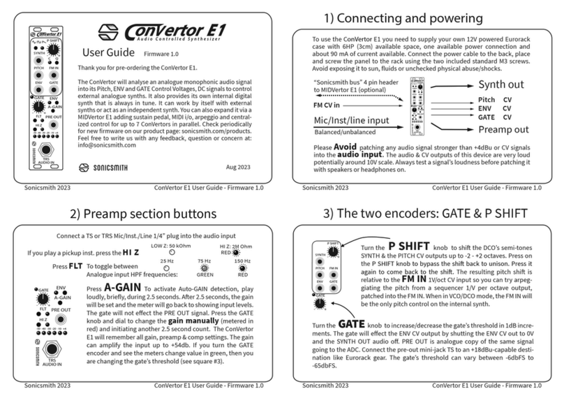
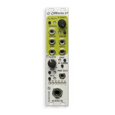
Sonicsmith ConVertor User manual

A udio Controlled Synthesizer
Owner’s manual
Semi-modular
audio controlled
analog synthesizer
21.7.2017 - Sonicsmith

-3--2-
The ConVertor general input and output map
Hello and thank you for purchasing a ConVertor synthesizer!
The ConVertor is a semi-modular, audio controlled, analog synthesizer. This
means,that it’s fully equipped to play a palette of sounds using a mono
audio signal alone, while still being able to communicate with modular synths
via CV signals. It generates its sound using a proprietary custom analog chip
called the Audio Controlled Oscillator (ACO100). The ACO chip has an analog
audio input at line level and is able to identify the fundamental frequency
(pitch) of a monophonic input audio. It then plays a square wave and a
sawtooth wave simultaneously at the pitch of the input audio (or optionally
at one of several discrete harmony intervals offset from the input audio) while
generating Con-trol Voltages (CV) representing pitch and gate. The gate’s
threshold is fixed at -48 dBu (post preamp). That means that as long as the
audio input is louder than -48dBu the gate will remain “open” (+9V) and let
the synthesized sound through to the output. When the input audio drops
below -48dBu the gate will be “closed” (0V) and the ACO’s output will be
silent. The pitch CV output of the ConVertor synth varies between 0V and 8V
at 1V per octave like other Eurorack compatible synths. The ACO is only one
part of this ACS (Audio Controlled Synth) and the following manual will
describe the rest of the parts and how they work with each other to create
musical sounds.
In the ConVertor all the audio inputs are accommodated via mono
instrument jacks (TS) at the back panel and all the CV inputs and outputsare
accommodated via mono mini jacks on the front panel. The only stereo
mini jack is the gate/trigger output which sharesa stereo mini jack. Plug a
mono mini jack to have the gate output, or use a stereo Y cable to split the
Gate CV from the L channel and the trigger CV output from the R channel.
Pitch tracking / The ACS
The ACO chip is powered from 4.5V and its inputs and outputs are scaled
to 9V (to achieve 1V/oct pitch CV) inside the ACS. Using the ACO, the
ConVertor completes the full blood stream of all modular synth essentials:
Pitch, ENV, gate and trigger CVs. The ACO can detect frequencies between
25Hz and 6kHz and will lock to the fundamental frequency as long as it’s
the strongest frequency in the audio. Some recommendations for better
pitch tracking include:
1. Switching to the neck pickup, as the bridge pickup generally contains
much more treble (more energy in higher harmonics).
2. Turning down the treble tone knob, if you have one.
3. Picking with your fingers instead of a pick if you can.
4. Playing as “cleanly” as possible - muting adjacent strings etc. The
ACO sometimes does some interesting things with polyphonic input but
make sure that's what you are going for.
2 examples of Audio Controlled Synths usage

Patching & Routing
1) 9V PSU input - Standard (minus inside) pedal power supply input. Note that
the ConVertor will not turn on until a TS jack is inserted into the main input (3)
2) POWER LED- When a power source (9V PSU / battery) is supplied and the
main input is plugged in, this red LED indicates that the synth is powered on.
3) Main INPUT - Mono (TS) instrument jack that can accept analog audio from
line level (tapes, CD’s…), instrument pickup levels (electric guitar and bass) or
down to microphone level sources (from dynamic mics). The input impedance
looking into this input is 100k ohms.
4) Main THRU out - Unbuered through connection to the main input.
5) PITCH CV out - 1V/octave 0-8V CV corresponding to the pitch detected by
the ACO from the main input.
6) ENV CV out - CV representation of the input’s level generated by an enve-
lope follower. The decay time constant of this envelope follower is about 43ms.
17) GATE / TRIG CV out - Stereo output with 9V gate CV out (from ACO) on
the left channel and 9V trigger CV out (15ms pulse width) on the right
channel. 17) Gate CV in - Secondary gate input (post-VCA). Gate threshold
voltage is 3.5v. Use a Y cable to split the gate (L) and thetrigger (R).
20) VCA CV in - Secondary VCA input. Plugging a cable into this input
bypasses the internal VCA.
21) OCTAVE CV in - Shifts the ACO output frequency by -2 to +2 octaves.
22) HARMONY CV in - CV input to shift ACO output frequency by -7 to +5
-4-
mix the dry signal into the output via the SRC/Synth mix knob.
6) Input HPF switch (high pass filter) - A 12dB/oct filter used to cut unwanted
low frequencies below the fundamental pitch. For example,if the user plays
regular electric guitar, he can benefit from filtering the input at 80Hz (down).
The minimum setting is 16Hz (up) and should be used if no filtering is desired.
8) LPF knob - Controls the input filter which can be used to emphasize the
lower frequencies and thus help with pitch detection. In general,it should be
set to fully counterclockwise unless you don’t like its effect. In that case you can
bypass it by turning this knob fully clockwise.
9) LPF TO switch - Sets the input filter to either the input where it can help
with pitch tracking or to the output where it’s audible.
13) ENV amount knob - The envelope (ENV) of an audio signal is the audio’s
amplitude behavior over time. The ENV CV in the ConVertor synth is
generated by an envelope follower (pre filters) and flows to the internal
VCA (affecting the synth’s volume) by default. The ENV follower detects the
level of the audio input and generates CV (control voltage) analogous to
the audio’s level between 0V and 8V. The ENV AMT knob can change the ENV
shape from 1:1 in its full clockwise position, through infinity:1 in the middle
position all the way to -1:1 (negative ENV) in the full counterclockwise
position, which is the complete opposite of the audio’s original envelope (ie.
instead of the ENV of a picked string decay down gradually, it will rise up
-5-
WARNING! Risk of permanent hearing damage!
Before the synth is patched to any guitar level device (ie. preamps/
amps/effects) turn down the OUTPUT level knob to around 9 o’clock!
DO NOT keep your head close to any amp speaker while you or
(especially) anyone else is changing the controls of the synth.
semitones in a just intonation scale (see table 1).
The proper voltage range for all CV inputs is 0-9v but they are protected
against signals with higher voltages than 9V so such signals won’t damage the
ConVertor synth.
The input section / ENV
5) InPut GAIN - Use this knob to amplify
the main input level. This preamp is
transparent and rangesfrom minimum 0dB
(no change) to +40dB.
7) Main input meter - This 4 character LED
meter will show you the audio input level.
The bottom LED illuminates when the gate
(-48dBu) is on, and the top LED will indicate
approximately when the input is too loud and
may be distorting. Clipping the input should
be avoided if possible as it can result in worse
frequency tracking and will be audible if you

-7--6-
HPF
16/80/
160Hz
LPF
80-6000Hz
IN
ENV
DET
THRU
ACO
PITCH
CV OUT
0-40dB
LFP to Input/Output
ENV
DET
SC
THRU
0/15dB
-1
ENV
AMT VCA
IN
VCA
OCT HRM
+ +
SQUARE
SAW GATE
TRIG
EXT
GATE
ENV
CV OUT
GATE/TRIG
CV OUT
SRC
SYNTH
OUT
Block diagram

-9--8-
gradually). Note that this control doesn’t affect the ENV which VCA isfed
internally. The VCA is always driven by the natural input signal envelope.
11) Side chain switch - While pitch detection will always be controlled by
the main input, the ConVertor has an additional ENV follower on the side
chain-audio input (#). The idea is to provide an optional alternative envelope
source with its own ENV follower with the decay time constant of about
9ms for fast response. At its bottom position,the S. C. ENV won’t have any
effect. In the middle position,the S. C. ENV will be engaged at unity gain and
its top position the input will be amplified +15 dBu to help adjust the audio
level of weaker sources. Using the ENV AMT knob but you cannot increase the
maximum ENV value detected by the ENV follower. So make sure you set the
input level high enough.
The oscillator of the ConVertor synthesizer is the ACO 100 chip. Unlike
other analog oscillators, it locks to an audio’s
frequency without needing to be tuned.
23) WAVE mix knob - This control is used to mix be-
tween the ACO’s 2 audio outputs: the square wave
and the sawtooth wave. You can smoothly mix be-
tween them to create any combination of the two
sounds. A square wave has only odd harmonics and
sounds “hollow” while the sawtooth wave has both
even and odd harmonics and thus sounds “sharper”.
24) OCTAVE knob - Use this control to shift the oscillator’s octave from -2 to
+2. The 12 o’clock position (indicated with U) will keep the oscillator play-ing
in unison with the audio input. This OCTAVE control can be simultaneously
controlled from the “octave” CV input (#).
25) HARMONY knob - Use this control to shift the oscillator’s pitch from -7
to +5 semitones on a just intonation scale. This scale does not adhere to the
familiar western equal-tempered scale and should be experimented with to
find your favorite settings. The table below shows a comparison between
the western scale and the ACO’s just intonation scale. This HARMONY
control can be simultaneously controlled from the “harmony” CV input (#).
The oscillator section
The output section
SRC MIX knob - Mixes between the source coming from the main input (count-
er clockwise) and the synth sound.
OUTPUT knob - Attenuates the main output from its line level output all the
way down to mute (counter clockwise). If you connect the main output to any
guitar oriented gear like preamps, amps or effects pedals, make sure to set
this knob to around 9 o’clock.
No sound
1) Make sure you have input signal and the level meter shows it’s loud enough
2) Make sure the output knob is not set too low
3) Make sure the side-chain switch is not engaged, and if it is,make sure you
have a healthy signal into the S. Chain input.
4) Make sure the filter is not set too low
Noisy output
1) Disconnect the main input. If the noise stops, try using a new cable or
troubleshoot the source instrument.
2) Make sure the LPF TO switch (#9) is set to the left (input) and set the
input filter (#8) to fully counter clockwise.
3) Turn the OUTPUT knob all the way counterclockwise. If you still hear the
noise,continue troubleshooting at the destination of the output/cable.
Troubleshooting
Outro
This audio controlled synth is a brand new technology and should be
experimented with.
Feel free to send us content you may create to our email:
media channels) what one can do with it.
We hope you have fun with your ConVertor and let us know your feedback!
Table of contents
Other Sonicsmith Synthesizer manuals
