Sonnen sonnenProtect-Plus User manual

Installation Guide
Page 1of 26
Installation Guide | for authorised electricians
sonnenProtect-Plus
Backup option for sonnenBatterie Hybrid 9.53
fdsfsf

Installation Guide
Page 2of 26
IMPORTANT
Read this document carefully before installation/ operation.
Retain this document for reference purposes.
Publisher
sonnen Australia
Lower Ground Floor, 61 Dunning Ave, Rosebery
NSW 2018, Australia
Service number
137 666
Email
[email protected]om.au
Document
Document number
10052021
Version
01
Valid for
AU, NZ
Publication date
10/05/2021

Installation Guide
Page 3of 26
Table of Contents
1Information about this document ..............................................................................4
1.1 Target group of this document....................................................................................................4
2Safety........................................................................................................................5
2.1 Intended Use............................................................................................................................5
2.2 Product modifications or changes to the product environment.............................................5
2.3 Voltage inside the sonnenProtect-Plus ...................................................................................6
3Product Description ...................................................................................................7
3.1 Technical Data..........................................................................................................................7
3.2 System components of the sonnenProtect-Plus .....................................................................8
4Operation..................................................................................................................9
4.1 Function ...................................................................................................................................9
4.1.1 Grid operation (grid available).............................................................................................9
4.1.2 Emergency operation (grid not available) ...........................................................................9
5Mounting.................................................................................................................11
5.1 Scope of delivery....................................................................................................................11
5.2 Mounting the sonnenProtect-Plus ........................................................................................12
6Electrical installation................................................................................................13
6.1 Installing the emergency circuit(s) ........................................................................................13
6.1.1 Electrical consumers in emergency operation ..................................................................13
6.1.2 Implementing the emergency circuit(s) ............................................................................15
6.2 Wiring procedure for the electrical installation ....................................................................15
7Commissioning ........................................................................................................22
7.1 Switching on the sonnenProtect-Plus and the storage system.............................................22
7.2 Setting up the sonnenProtect-Plus........................................................................................22
7.3 Changing the backup buffer using the Web Interface of the storage system ......................23
8sonnenBatterie Protect-Plus Configurations .............................................................24

Installation Guide
Page 4of 26
1Information about this document
This document describes the installation of the sonnenProtect-Plus in connection with
the sonnenBatterie Hybrid 9.53 storage system.
Read this document in its entirety.
Keep this document in the vicinity of the sonnenProtect-Plus.
1.1 Target group of this document
This document is intended for authorised electricians. The actions described here must only
be performed by authorised electricians.

Installation Guide
Page 5of 26
2Safety
2.1 Intended Use
The sonnenProtect-Plus is an emergency power unit designed to supplement the
sonnenBatterie Hybrid 9.53 to supply single-phase backup power in the event of a power
failure. Any other use is considered improper use.
Improper use poses a risk of death or injury to the user or third parties as well as damage to
the product and other items of value. The following points must therefore be observed in
order to comply with the intended use of the product:
•Only operate the sonnenProtect-Plus together with sonnenBatterie Hybrid 9.53.
•The minimum capacity of the storage system required for the operation of the
sonnenProtect is 5 kWh (2 battery modules).
•The sonnenProtect-Plus must be installed by an authorised licensed electrician.
•The sonnenProtect-Plus must only be connected to the storage system as described
here.
•Intended use includes observing the diagrams and schematics contained within this
document as well as all accompanying product documentation of sonnenBatterie
Hybrid 9.53, and not modifying any of the pre-wired/ installed connections and/ or
components supplied with the device.
•The sonnenProtect-Plus must only be used at suitable installation location.
•Sensible transport and storage conditions must be observed.
The following uses are not permissible:
•Operation in flammable environments or areas at risk of explosion.
•Operation in locations at risk of flooding.
•Operation in an outdoor location whereby the supplied IP rating of the enclosure has
not remained intact.
Failure to comply with the conditions detailed here invalidates any warranty
claims.
2.2 Product modifications or changes to the product environment

Installation Guide
Page 6of 26
•The sonnenProtect-Plus must only be used in its original state without any user
modifications and only when in perfect working order.
•Safety devices must never be overridden, blocked, or tampered with.
•The interfaces of the sonnenProtect-Plus and the storage system must be wired in
accordance with the product documentation.
•All repairs on the sonnenProtect-Plus must be performed by authorised sonnen
service technicians only.
2.3 Voltage inside the sonnenProtect-Plus
The sonnenProtect-Plus contains live electrical parts, which poses a risk of
electrical shock. The storage system inverter also contains capacitors which
carry voltage even after the storage system is switched off. As the
sonnenProtect-Plus is connected to the inverter of the storage system, this
means that the voltage from the inverter also flows into the sonnenProtect-
Plus. Therefore:
Disconnect the sonnenProtect-Plus and the storage system from the power supply.
Only then can the sonnenProtect-Plus be opened.

Installation Guide
Page 7of 26
3Product Description
3.1 Technical Data
We reserve the right to update or modify any information. All values, information, images and illustrations in this data sheet,
brochures and all other publications are exemplary and are subject to on-going changes and updates. Unless expressly designated
as binding all this information is provided with no assurances. Only the specifications in the binding order acceptance or the
purchase contract are valid.
* The switch to emergency operation takes place automatically through the storage system.

Installation Guide
Page 8of 26
3.2 System components of the sonnenProtect-Plus
Figure 1: System components of sonnenProtect-Plus with covers
Figure 2: System components of sonnenProtect-plus with covers removed.
1
Miniature circuit breakers
2
Power Meter
3
Switches
4
Cover
5
Cover notches
6
Transformer interfaces
7
Current transformers
8
Snap connectors
9
RJ-45 coupling for Modbus line

Installation Guide
Page 9of 26
4Operation
4.1 Function
The sonnenProtect-Plus is simple and universal in its design. The product comes completely
pre-wired and requires the installer to connect the grid supply, normal loads, essential loads
and optionally an AC-coupled PV system. Another benefit is also the sonnen Power Meter
that is already an integral part of the sonnenProtect-Plus. sonnenBatterie Hybrid 9.53 with
sonnenProtect-Plus automatically switches from grid to backup operation and vice versa.
The two operating modes are described in the following.
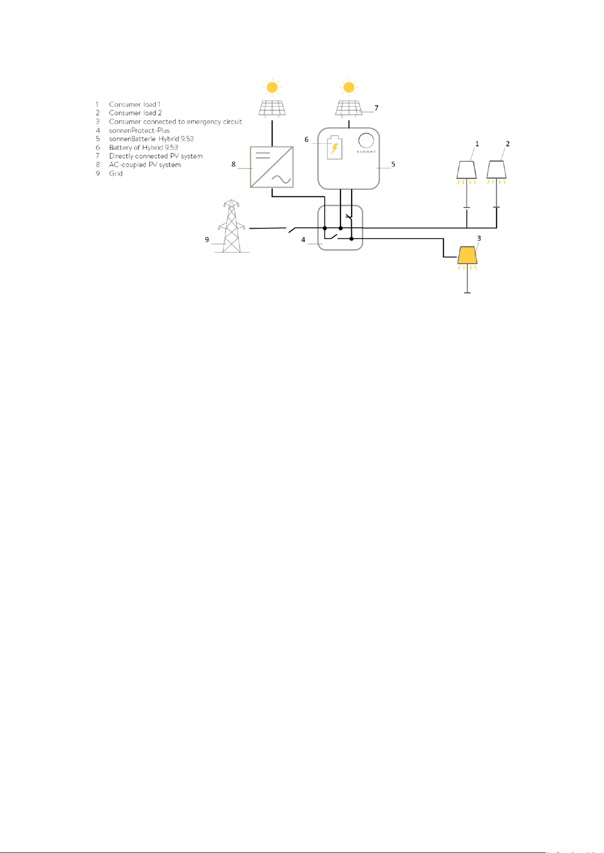
4.1.1 Grid operation (grid available)
In normal grid operation, the normal loads (1-2) and the essential loads which are
connected to the emergency circuit (3) are supplied with power. In this scenario, the grid
(9), sonnenBatterie Hybrid9.53 (5) and the optional AC-coupled PV system (8) all supply
power to the loads. The storage system controls –as described in the product
documentation of the storage system - the energy flow of the installation.
Figure 3: Grid operation- no grid outage
4.1.2 Emergency operation (grid not available)
The sonnenProtect-Plus (4) automatically detects a grid outage and therefore the
connection to the grid (9) is disconnected. Both normal and essential loads (1-3) in the
building as well as any AC-coupled PV system (8) will disconnect due to the grid outage.
Emergency power is generated after max. 15 seconds. The essential loads connected to the
emergency circuit (3) in the building are thereby supplied with electrical power. However,
the normal loads (1-2) will not be supplied with electrical power. The switchover from grid
to emergency operation is signalled by the Eclipse on the storage system. The colour of the
Eclipse changes from white (normal operation) to green (emergency operation).
Installation Guide
Page 10 of 26
Figure 4: Emergency operation- grid outage
Electrical power generated by the PV system connected directly to sonnenBatterie
Hybrid9.53 (7) continues to be used by the storage system to supply power to the essential
loads (3) and to charge the battery (6).
sonnenBatterie Hybrid 9.53 with sonnenProtect-Plus switches from emergency to grid
operation as soon as the grid starts to deliver electrical power again.
Automatic stop and resumption of the emergency operation
The storage system with sonnenProtect-Plus generates power until a minimum state of
charge of the battery is reached. Thereafter, no further discharge is allowed.
If the discharge has stopped due to the minimum state of charge, the storage system
remains in this state until the directly connected PV system starts to produce power again.
Then, the batteries of the storage system are charged and as soon as the state of charge
exceeds the minimum limit, the surplus power is used to supply power to the essential
loads.

Installation Guide
Page 11 of 26
5Mounting
5.1 Scope of delivery
Check the following scope of delivery to ensure it is complete.
Figure 5: Scope of delivery
The pre-wired sonnenProtect-Plus has simplified the installation of the sonnenBatterie
Hybrid 9.53 with backup functionality and integrability with an optional AC-coupled PV
system. It comes with all the AC MCBs, RCBO and sonnen Power Meter with CTs enclosed
within an IP66 outdoor enclosure. The sonnenProtect-Plus includes full pre-installed
labelling as prescribed within the application AS/NZS Standards.
Within the enclosure, you will find the wiring assembly for the backup circuit and some of
the other accessories that normally come with the Hybrid 9.53 main unit, installation
manuals, fixings and the battery cables. The sonnenProtect-Plus comes supplied with the
backup cable to run between the sonnenProtect-Plus and the sonnenBatterie. There is also
included the enclosure mounting kit and keys for opening / locking it.

Installation Guide
Page 12 of 26
5.2 Mounting the sonnenProtect-Plus
Locate the mounting brackets and place them on the rear of the enclosure. It is
recommended to install these brackets facing out at 45 degrees to ensure even distribution
of the weight of the enclosure. Then, place the enclosure on the wall and fix it as required.
Figure 8: sonnenProtect-Plus mounted on the wall.
Figure 6: Mounting brackets facing out at 45 degrees at
the ear of the enclosure.
Figure 7: Mounting bracket

Installation Guide
Page 13 of 26
6Electrical installation
The pre-wired sonnenProtect-Plus has simplified the installation of the sonnenBatterie
Hybrid 9.53 with backup functionality and integrability with an optional AC-coupled PV
system. It comes with all the AC MCBs, RCBO and sonnen Power Meter with CTs enclosed
within an IP66 outdoor enclosure. The sonnenProtect-Plus includes full pre-installed
labelling as prescribed within the application AS/NZS Standards.
Electrical work on the storage system, the backup product, and electrical distributor
Danger to life due to electrocution!
Switch off the storage system to electrically isolate it.
Disconnect the relevant electrical circuits.
Secure against anyone switching on the device again.
Wait five minutes so the capacitors can discharge.
Check that the device is disconnected from the power supply.
Only authorised electricians are permitted to carry out electrical work.
Observe maximum line lengths.
The lines connected to the storage system (mains line, Ethernet line, other data lines) are
NOT allowed to exceed a maximum length of 30 meters.
6.1 Installing the emergency circuit(s)
6.1.1 Electrical consumers in emergency operation
Before installation, the installer must explain or clarify with the operator the following
points:
•Emergency operation does not offer the same output as grid operation.
•Three-phase supply is not available during emergency operation (as only one phase
is supplied with power).
•The minimum capacity of the storage system required for the operation of the
sonnenProtect is 5 kWh (2 battery modules).
•Which electrical consumers should be supplied with power in emergency
operation? The current paths in the building network must be installed in such a way
that the consumers which are relevant in the event of a grid outage are connected to
an independent circuit (emergency circuit). The electrical consumers which are
crucial for the operator in emergency operation are relevant here. Different

Installation Guide
Page 14 of 26
consumers which may be important during a grid outage are specified in the sample
calculation presented below.
•How much capacity of the storage system should be reserved as backup buffer?
The following example, in which a utility room and other important functions within
a single-family home are to be supplied with power, can be used to determine this.
This example is based on a grid outage lasting one hour (the individual power
consumption values are estimated values).
In this example the total power requirement for a grid outage lasting one hour is approx. 1.1
kWh, in order to maintain the function of all the listed consumers.
Use this calculation to determine with the operator which backup buffer should be
set, taking the total capacity of the storage system and other requirements (e.g.,
from sonnenFlat tariff) into account (see Section 7.2 Setting up the sonnenProtect-
Plus and Section 7.3 Changing the backup buffer using the Web Interface of the
storage system).

Installation Guide
Page 15 of 26
6.1.2 Implementing the emergency circuit(s)
Basics for the formation of the emergency circuits:
•For systems with emergency power capability, the power distribution must be
separated into emergency power authorised and not emergency power authorised
parts.
•All components within the emergency power authorised part must be clearly
identified by lettering (or graphic symbols).
At any time observe further local and national requirements and guidelines
regarding emergency power supply!
When undertaking electrical work on the distributor in the building, the following must be
taken into account, among other things:
1- How is the wiring set up to the desired backup consumers?
-Is independent wiring already in place?
-Do the existing circuits include electrical consumers that should not be supplied
with power in backup operation?
-Can the existing wiring be split?
-If the circuits cannot be split, the connected wattage of the consumers which
should not be supplied with backup power needs to be taken into account. If
loads are too high, the circuit breaker for the sonnenProtect-Plus will trip, and
then none of the electrical consumers in the backup circuit will be supplied with
power.
6.2 Wiring procedure for the electrical installation
Important: The mains grid supply must be connected directly to the sonnenProtect-Plus,
and from there, to connect to two sub-circuits: one for normal domestic loads and one for
the essential loads. Note that the essential loads which were previously part of the normal
loads, must now be isolated as a sub-circuit. This sub-circuit as the essential loads are wired
in a way so they will be specifically powered from the sonnenProtect-Plus during emergency
operation.
Carry out the steps in the following order to ensure the correct electrical installation of the
sonnenProtect-Plus:

Installation Guide
Page 16 of 26
Opening the enclosure of the sonnenProtect-Plus
Use the lever provided in the accessories kit to open the enclosure door. Insert a small
screwdriver into the notches to unclick and remove the covers.
Before starting the wiring process of the sonnenProtect-Plus, switch off all the circuits to the
property.
Drilling through the enclosure must be performed at high speed with low pressure applied.
1- Drill through the enclosure to insert gland entries. Drilling holes must be performed
at high speed while applying low pressure to ensure that the IP rating of the
enclosure (IP66) is retained.
•It is recommended to remove the frame prior drilling through the enclosure
to avoid contamination of the electrical equipment.
•Cable glands must be provided by the installer.
2- Locate the incoming main AC supply from the grid and connect it directly into the
“Grid Supply” labelled snap connectors in the sonnenProtect-Plus. These connectors
can take up to 16 mm CSA cables.
3- Connect the normal loads into the “Normal Loads” labelled snap connectors in the
sonnenProtect-Plus. These connectors can take up to 16 mm CSA cables.
4- Connect the essential loads into the “Backup Loads” labelled snap connectors in the
sonnenProtect-Plus. These connectors can take up to 10 mm CSA cables.

Installation Guide
Page 17 of 26
Figure 9: Snap connectors in the sonnenProtect-Plus
5- Connect the AC-coupled PV system (if any) into the “Solar Supply” labelled snap
connectors in the sonnenProtect-Plus. These connectors can take up to 10 mm CSA
cables.
6- Connect the sonnenBatterie main unit to the sonnenProtect-Plus using the provided
AC mains cable of the main unit. Connect the AC mains cable to the
“sonnenBatterie” labelled snap connectors in the sonnenProtect-Plus as illustrated in
Figure 10. These connectors can take up to 10 mm CSA cables.
Figure 10: The AC mains line provided with Hybrid 9.53.

Installation Guide
Page 18 of 26
Connecting the Backup Supply
Important: The provided backup supply cable carries the power supply lines as well as the
24VDC supply (Grey, White and Black) for the contactors.
1- Strip the backup supply cable sheath to approximately 200mm; then shorten the
24VDC conductors (Grey, White and Black) to 100mm.
2- Using the provided backup supply cable, connect the emergency power output of
the sonnenBatterie unit to the “Backup Supply” labelled snap connectors in the
sonnenProtect-Plus. These connectors can take up to 10 mm CSA cables.
3- Connect the 24VDC supply to the “Contactors” labelled snap connectors on the
bottom DIN rail of the sonnenProtect-Plus enclosure, as illustrated in Figure 11.
Figure 11: Connecting the Backup Supply and the 24VDC for contactors.


Installation Guide
Page 20 of 26
Connecting the sonnen Power Meter
Important: The RJ-45 coupling for Modbus line is located on the bottom DIN rail of the
sonnenProtect-Plus enclosure, as demonstrated in Figure 13.
Figure 13: RJ-45 coupling of the Modbus line for connecting the sonnen power Meter.
1- As the sonnen Power Meter is pre-wired, plug a suitable data cable such as shielded
Cat 6 into the RJ-45 coupling socket in the sonnenProtect-Plus.
2- Plug in the Modbus cable for the metering to the XSO2 Modbus port on Hybrid 9.53
as illustrated in Figure 14.
Figure 14: Connecting the Modbus line to Hybrid 9.53.
Table of contents
Other Sonnen Portable Generator manuals


Popular Portable Generator manuals by other brands


Champion Power Equipment
Champion Power Equipment 71330 Owner's manual & operating instructions

Zipper Mowers
Zipper Mowers ZI-STE2000IV user manual

Yamaha
Yamaha EF1000 Service manual

Yamaha
Yamaha EF1000iS owner's manual

National Instruments
National Instruments NI PXIe-5673E CALIBRATION PROCEDURE

Southwest Windpower
Southwest Windpower Whisper 100 owner's manual

Briggs & Stratton
Briggs & Stratton 30554 Operator's manual

MAXPhotonics
MAXPhotonics MFSC CW Fiber Laser Series user guide

Westerbeke
Westerbeke 3.0 BPMG Operator's manual

Yuchai
Yuchai YC4D60-D21 Maintenance manual

Generac Power Systems
Generac Power Systems MLG8 operating manual

A-iPower
A-iPower POWER SUA5000 quick start guide