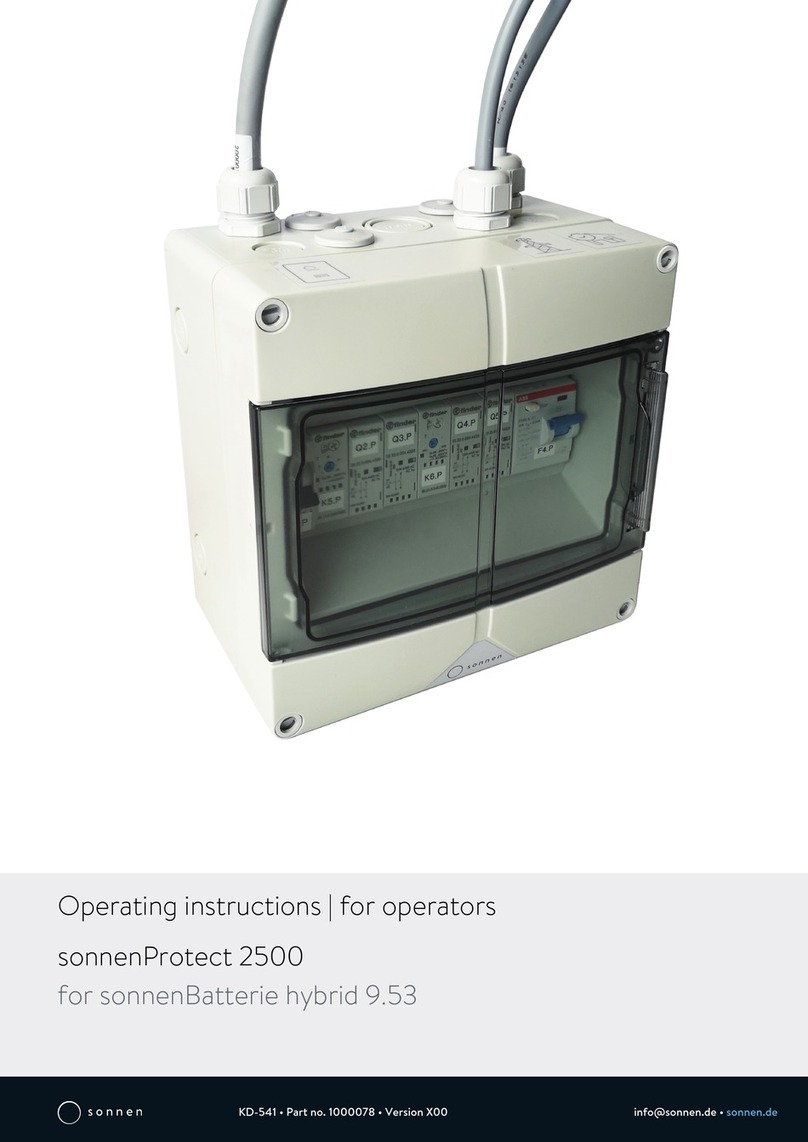
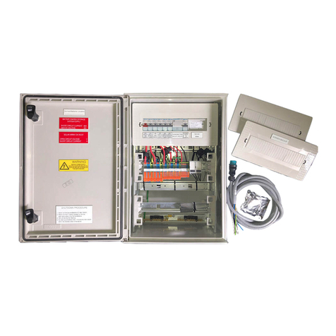
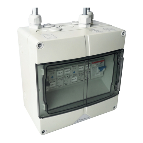
Sonnen Protect 1300 User manual

Installation instructions | for authorised electricians
sonnenProtect 1300
for sonnenBatterie eco 8.2 or eco 9.43
KD-345 • Part no. 22041 • Version X02 [email protected] • sonnenbatterie.de

Publisher
sonnen GmbH
Am Riedbach 1
D-87499 Wildpoldsried
Service number
Email
Document
Document number 345
Part number 22041
Version X02
Valid for UK
Publication date 19/02/2018
IMPORTANT
Read this documentation carefully before installation / operation.
Retain this document for reference purposes.
EN
Installation instructions sonnenProtect 1300

Table of contents
KD-345 | 22041 | EN | X02 iii
Table of contents
1 Information about this document ..................................................................................................5
1.1 Target group of this document ..............................................................................................5
1.2 Designations in this document ..............................................................................................5
1.3 Explanation of symbols...........................................................................................................5
2 Safety................................................................................................................................................ 7
2.1 Intended use ............................................................................................................................ 7
2.2 Requirements for the electrician .......................................................................................... 7
2.3 Operating the sonnenProtect ............................................................................................... 7
2.4 Product modifications or changes to the product environment ........................................8
2.5 Voltage inside the sonnenProtect.........................................................................................8
3 Product description ......................................................................................................................... 9
3.1 Technical data..........................................................................................................................9
3.2 System components .............................................................................................................10
3.2.1 System components of the sonnenProtect...........................................................10
3.2.2 Control and display elements..................................................................................10
3.3 Function.................................................................................................................................. 11
3.4 Type plate............................................................................................................................... 12
3.5 Symbols on the outside of the sonnenProtect................................................................... 13
4 Transport and storage.................................................................................................................... 14
5 Mounting .........................................................................................................................................15
5.1 Scope of delivery................................................................................................................... 15
5.2 Selecting the installation location ....................................................................................... 15
5.2.1 Requirements for the installation location............................................................. 15
5.2.2 Observe minimum distances ................................................................................... 16
5.3 Mounting the sonnenProtect .............................................................................................. 16
6 Installation with sonnenBatterie eco 8.2......................................................................................17
6.1 Removing the inverter cover ................................................................................................17
6.2 Installing the mains filter.......................................................................................................17
6.2.1 Case 1: Sufficient free space on mounting rail ......................................................18
6.2.2 Case 2: Not enough free space on mounting rail..................................................18
6.3 Connecting the cable and strands....................................................................................... 19
6.3.1 Removing the dummy plug ..................................................................................... 19
6.3.2 Installing the cable gland.......................................................................................... 19
6.3.3 Wiring the cable.......................................................................................................20
6.3.4 Connecting the cables and strands........................................................................20
6.4 Completing installation ........................................................................................................ 21
7 Installation with sonnenBatterie eco 9.43 ..................................................................................22
7.1 Changes to the storage system ...........................................................................................22
7.1.1 Storage system fuse protection ..............................................................................22
7.1.2 Measurement concept used ....................................................................................22

Table of contents
iv Installation instructions sonnenProtect 1300
7.2 Installing the mains filter................................................................................................23
7.3 Connecting the cable and strands.................................................................................24
7.3.1 Removing the dummy plug ...............................................................................24
7.3.2 Installing the cable gland....................................................................................24
7.3.3 Wiring the cable..................................................................................................25
7.3.4 Connecting the cables and strands...................................................................25
8 Commissioning......................................................................................................................... 27
8.1 Commissioning the storage system ..............................................................................27
8.1.1 Switching on the miniature circuit breaker......................................................27
8.1.2 Switching on the storage system ......................................................................27
8.1.3 Switching on the grid voltage ............................................................................27
8.2 Testing function .............................................................................................................. 27
8.3 Setting up the sonnenProtect .......................................................................................28
8.3.1 Generating a commissioning code....................................................................28
8.3.2 Establishing connection to the storage system...............................................28
8.3.3 Setting the backup buffer..................................................................................29
9 Troubleshooting.........................................................................................................................31
10 Decommissioning..................................................................................................................... 32
10.1 Switching off the plug outlet .........................................................................................32
10.2 Disconnecting the sonnenProtect from the power supply.........................................32
11 Uninstallation and disposal......................................................................................................33
11.1 Uninstallation ..................................................................................................................33
11.2 Disposal............................................................................................................................33

Information about this document | 1
KD-345 | 22041 | EN | X02 5 / 36
1 Information about this document
This document describes the installation of the sonnenProtect 1300 in connection
with the sonnenBatterie eco 8.2 or eco 9.43 storage system.
Read this document in its entirety.
Keep this document in the vicinity of the sonnenBatterie.
1.1 Target group of this document
This document is intended for authorised electricians. The actions described here must
only be performed by authorised electricians.
1.2 Designations in this document
The following designations are used in this document:
Complete designation Designation in this document
sonnenBatterie eco 8.2 Storage system
sonnenBatterie eco 9.43
sonnenProtect 1300 sonnenProtect
1.3 Explanation of symbols
DANGER Extremely dangerous situation leading to certain death or serious injury if the
safety information is not observed.
WARNING Dangerous situation leading to potential death or serious injury if the safety in-
formation is not observed.
CAUTION Dangerous situation leading to potential injury if the safety information is not ob-
served.
NOTICE Indicates actions that may cause material damage.
Important information not associated with any risks to people or property.
Symbol Meaning
►Work step
1. 2. 3. … Work steps in a defined order
üCondition

1 | Information about this document
6 / 36 Installation instructions sonnenProtect 1300
Symbol Meaning
●List
Table1: Additional symbols

Safety | 2
KD-345 | 22041 | EN | X02 7 / 36
2 Safety
2.1 Intended use
The sonnenProtect 1300 is an emergency power unit designed to supplement the
sonnenBatterie eco 8.2 or eco 9.43. The sonnenProtect provides power to the con-
nected consumer even if a grid outage occurs. It can only be operated together with
the right storage system from sonnen GmbH. Any other use is considered improper
use.
Improper use poses a risk of death or injury to the user or third parties as well as dam-
age to the product and other items of value. The following points must therefore be
observed in order to comply with the intended use of the product:
• Only operate the sonnenProtect together with the right storage system.
• The sonnenProtect must be installed by an authorised electrician.
• The sonnenProtect must only be connected to the storage system as described
here. The output of the sonnenProtect must not be connected to the building
mains.
• Only connect an electrical consumer that does not exceed the nominal power (in
continuous operation) and maximum power (when switched on) of the
sonnenProtect.
• The sonnenProtect must only be used at suitable installation location.
• The transport and storage conditions must be observed.
Failure to comply with the conditions of the warranty and the information spe-
cified in this document invalidates any warranty claims.
2.2 Requirements for the electrician
Improper installation can result in personal injury and/or damage to components. For
this reason, the sonnenProtect must only be installed and commissioned by authorised
electricians. Authorised electricians must meet the following criteria:
• The electrician must be a person with a technical knowledge or sufficient experience
to enable him/her to avoid dangers which electricity may create.
• The company for which the electrician works must be certified by sonnen GmbH.
• The electrician must have successfully complete sonnen GmbH certification train-
ing for the product.
2.3 Operating the sonnenProtect
Incorrect operation can lead to injury to yourself or others and cause damage to prop-
erty.
• The sonnenProtect must only be operated as described in the product documenta-
tion.

2 | Safety
8 / 36 Installation instructions sonnenProtect 1300
• This device can be used by children from the age of eight (8) years old and individu-
als impaired physical, sensory or mental capabilities or individuals with limited know-
ledge and/or experience of working with the device, as long as they are supervised or
have been trained to safely use the device and understand the resulting risks of do-
ing so. Children must not play with the device. Cleaning and user maintenance must
not be carried out by children without supervision.
2.4 Product modifications or changes to the product
environment
• The sonnenProtect must only be used in its original state without any user
modifications and only when in perfect working order.
• Safety devices must never be overridden, blocked or tampered with.
• The interfaces of the sonnenProtect and the storage system must be wired in
accordance with the product documentation.
• The number of plug outputs on the sonnenProtect must not be changed.
• All repairs on the sonnenProtect must be performed by authorised service techni-
cians only.
2.5 Voltage inside the sonnenProtect
5 min
The sonnenProtect contains live electrical parts, which poses a risk of electrical shock.
The storage system inverter also contains capacitors which carry voltage even after the
storage system is switched off. As the sonnenProtect is connected to the inverter of
the storage system, this means that the voltage from the inverter also flows into the
sonnenProtect. Therefore:
Disconnect the sonnenProtect from the power (see Disconnecting the sonnen-
Protect from the power supply [P.32]).
Only then can the sonnenProtect be opened.

Product description | 3
KD-345 | 22041 | EN | X02 9 / 36
3 Product description
3.1 Technical data
sonnenProtect 1300
System data
Maximum power (2 sec.) 2,200W
Nominal power 1,300W
Output voltage (AC) 230V +/- 10%
Nominal frequency 50Hz
Network configuration in emergency opera-
tion
IT
Operating concept Single-phase power supply via plug outlet. The
switch to emergency operation takes place
automatically through the storage system.
Switchover time to emergency operation approx. 5 seconds
Dimension/Weight
Dimensions (H/W/D) in mm 235/150/124
Weight in kg approx. 2kg
Safety
Protection class I (PE conductor)
Degree of protection IP21
Overvoltage category III
Protective functions Overcurrent protection, insulation monitor
(as per IEC 61557-8)
Ambient conditions
Environment indoor (conditional)
Ambient temperature range 5 °C ... 30 °C
Storage temperature range 0 °C ... 40 °C
Transport temperature range -15°C ... 30 °C
Max. rel. humidity 90 %, non-condensing
Permissible installation altitude 2,000 m above sea level
Pollution degree 2
Additional ambient conditions The ambient conditions prescribed for the
storage system apply.
Table2: Technical data

3 | Product description
10 / 36 Installation instructions sonnenProtect 1300
3.2 System components
3.2.1 System components of the sonnenProtect
1
2
520
40
60
80
100
ON AL
Test
Reset
3 4
Illustration1: System components sonnenProtect
1 sonnenProtect 2 Plug outlet
3 F1.P (Z6) miniature circuit breaker 4 K2.P insulation monitor
3.2.2 Control and display elements
520
40
60
80
100
ON AL
Test
Reset
4
6
3
5
2
RAL
kΩ
F1.P
K2.P
1
Illustration2: Control and display elements
No. Designation Function
1 Miniature circuit
breaker
Reversing the switch activates/deactivates the plug outlet of
the sonnenProtect.

Product description | 3
KD-345 | 22041 | EN | X02 11 / 36
No. Designation Function
2 ‘ON” LED Lights up when power supply is on (indicates emergency opera-
tion).
3 ‘AL’ LED Lights up when an insulation fault occurs, i.e. when the insula-
tion resistance drops below the set alarm value (RE < RAL) (in
emergency operation).
4 Test key Pressing the test key simulates an insulation fault, thereby
testing the function of the device. The ‘AL’ LED lights up and
the connection to the plug outlet of the sonnenProtect is in-
terrupted for as long as the test key is held.
5 Reset key No function.
6 RAL setting Turning sets the RAL alarm value (recommended setting:
100kΩ/V).
Table3: Description of the control and display elements
3.3 Function
The plug outlet oft the sonnenProtect supplies electrical power both in grid and emer-
gency operation. The switchover time between grid and emergency operation is stated
in the section Technical data [P.9].
520
40
60
80
100
ON AL
Test
Reset
RAL
kΩ
RCD
1
2 3 4
56
7
8
Illustration3: Grid operation
The insulation monitor (5) deactivates in
grid operation
(‘ON’ LED off). Protection
against indirect contact is ensured by the residual current device(RCD) at the feed to
the storage system.

3 | Product description
12 / 36 Installation instructions sonnenProtect 1300
520
40
60
80
100
ON AL
Test
Reset
RAL
kΩ
RCD
1
2 3 4
56
7
8
Illustration4: Emergency operation
1 Plug outlet of the sonnenProtect
2 sonnenProtect
3 F1.P miniature circuit breaker
4 Storage system
5 Insulation monitor
6 AC miniature circuit breaker
7 Residual current device (RCD) - 30mA
8 Public grid (electrical mains)
If a
grid outage
occurs, the connection to the public grid is disconnected in the storage
system. The plug outlet (1) is supplied with electrical power from the storage system
until the battery’s minimum charging status is achieved. The insulation monitor is ac-
tivated (‘ON’ LED lights up). This protects against indirect contact.
If an insulation fault occurs (RE < RAL), the insulation monitor terminates the connec-
tion to the plug outlet. The ‘AL’ LED lights up. When the insulation fault no longer ex-
ists, the connection to the plug outlet is automatically reestablished. The ‘AL’ LED
goes out.
The storage system switches back to grid operation with a delay after a grid outage.
This can take a few minutes. During this time the plug outlet is supplied with power in
emergency operation.
3.4 Type plate
The type plate is located on the outer surface of the sonnenProtect. The type plate
can be used to uniquely identify the sonnenProtect. The information on the type plate
is required for the safe use of the system and for service matters.
The following information is specified on the type plate:
• Item designation
• Item number

Product description | 3
KD-345 | 22041 | EN | X02 13 / 36
• Technical data
3.5 Symbols on the outside of the sonnenProtect
Symbol Meaning
Warning: electrical voltage.
5 min
Warning: electrical voltage. Wait five minutes after switching off
(capacitor de-energising time).
CE mark. The product meets the requirements of the applicable
EU Directives.
WEEE mark. The product must not be disposed of in household
waste, dispose of it through environmentally friendly collection
centres.
Observe the documentation. The documentation contains safety
information.

4 | Transport and storage
14 / 36 Installation instructions sonnenProtect 1300
4 Transport and storage
Transport and storage conditions are defined in the product documentation of the
storage system.
Observe the same transport and storage conditions for the sonnenProtect.

Mounting | 5
KD-345 | 22041 | EN | X02 15 / 36
5 Mounting
5.1 Scope of delivery
Check the following scope of delivery to ensure it is complete.
520
40
60
80
100
ON AL
Test
Reset
1
2
6 5 4
9
10
7
3
8
LINE
LOAD
N L
N' L'
Illustration5: Scope of delivery
1 sonnenProtect including connection cable
2 M20 cable gland
3 Mains filter
4 Pre-assembled strand - PE
5 Pre-assembled strand - N
6 Pre-assembled strand - L
7 Locking nut
8 Wire end ferrule (only for installation with eco 9.43)
9 Cable lug (only for installation with eco 9.43)
10 Connector X3 (only for installation with eco 9.43)
5.2 Selecting the installation location
5.2.1 Requirements for the installation location
Observe the required ambient conditions (see Technical data [P.9]).

5 | Mounting
16 / 36 Installation instructions sonnenProtect 1300
5.2.2 Observe minimum distances
30 cm
15 cm
Illustration6: Minimum distances
Observe the specified minimum dis-
tances between the device and the stor-
age system and neighbouring objects.
Install the sonnenProtect at the same
level as the top edge of the storage sys-
tem, if possible. This keeps the cable
length as short as possible.
The minimum distances ensure that
• the sonnenProtect can be easily reached and
• there is sufficient space for installation and maintenance work.
5.3 Mounting the sonnenProtect
1610
1532
838,5
50
110
15
95
50 38
Illustration7: Drill template for sonnenProtect (fig-
ure is not to scale - all specifications are in milli-
metres)
Drill the holes shown in red in the il-
lustration on the left.
Secure the sonnenProtect using ap-
propriate fastening material.

Installation with sonnenBatterie eco 8.2 | 6
KD-345 | 22041 | EN | X02 17 / 36
6 Installation with sonnenBatterie eco 8.2
DANGER Electrical work on the storage system
Danger to life due to electrocution!
Switch off the storage system to electrically isolate it.
Disconnect the relevant electrical circuits.
Secure against anyone switching on the device again.
Wait five minutes so the capacitors can discharge.
Check that the device is disconnected from the power supply.
Only authorised electricians are permitted to carry out electrical work.
6.1 Removing the inverter cover
NOTICE Contact with the components inside the inverter
Damage to components due to electrostatic discharge (ESD)!
Use ESD-compliant equipment.
Do not touch any conductive components inside the inverter.
1
2
Illustration8: Inverter cover and touch guard in-
side the storage system
Tools:
• Allen screw | 5mm
• Spanner | 10mm
Open the storage system.
Remove the touch guard (2) and the
cover (1) for the inverter.
6.2 Installing the mains filter
The components inside the storage system can be arranged differently. This
means that the installation of the main filter may vary.
In the following, select the appropriate case and install the mains filter accordingly.

6 | Installation with sonnenBatterie eco 8.2
18 / 36 Installation instructions sonnenProtect 1300
6.2.1 Case 1: Sufficient free space on mounting rail
LINE
LOAD
N L
N' L'
Illustration9: Installation on mounting rail
Remove the end stop on the left side
of the relay K1 on the mounting rail.
Install the mains filter on the mount-
ing rail.
6.2.2 Case 2: Not enough free space on mounting rail
LINE
LOAD
N L
N' L'
Illustration10: Installation on bolts
Remove the mounting plate with DIN
rail adapter which is mounted on the
mains filter.
Mount the mains filter on the two free
bolts using the two supplied locking
nuts, as shown in the left figure.

Installation with sonnenBatterie eco 8.2 | 6
KD-345 | 22041 | EN | X02 19 / 36
6.3 Connecting the cable and strands
6.3.1 Removing the dummy plug
B+
B
-
ON
12 34
1
Illustration11: Dummy plugs on the top of the
storage system
Tools:
• Screwdriver with a thin blade (0.4mm)
Remove the dummy plug (1).
A screwdriver with a thin blade can be
used for this purpose.
6.3.2 Installing the cable gland
B+
B
-
ON
12 34
Illustration12: Installing the cable gland on the top
of the storage system
Tools:
• Spanner | 25mm
Install the cable gland as shown in the
left illustration.

6 | Installation with sonnenBatterie eco 8.2
20 / 36 Installation instructions sonnenProtect 1300
6.3.3 Wiring the cable
Illustration13: Connection cable of the
sonnenProtect
Wire the connection cable of the
sonnenProtect through the cable
gland to the inside of the storage sys-
tem.
6.3.4 Connecting the cables and strands
Tools:
• Spanner | 10mm | 5Nm
• Stripping pliers
Strip approx. 1cm from the end of the black and grey cable.
Connect the cable and pre-assembled strands as shown in the following illustra-
tions. Run the strands through the cable gland (3) to the inside of the inverter (1).
Tighten the self-locking nut (6) with a torque of 5Nm.
Table of contents
Other Sonnen Portable Generator manuals
Popular Portable Generator manuals by other brands

Lincoln Electric
Lincoln Electric INVERTEC 165S Operator's manual

Powermate
Powermate Black Max PM0676800 user manual
DINKING
DINKING DK3300i user manual

Westerbeke
Westerbeke BTD 7.5 KW 50H Operator's manual
Dometic
Dometic T4000 H/HG-LP Installation and operating manual
A-iPower
A-iPower SUA12000ED quick start guide
DINKING
DINKING DK4000i user manual

FG Wilson
FG Wilson OLYMPIAN 1001 Series manual
Star Industrial Supply Chain
Star Industrial Supply Chain E-300 Operating instruction
Caviblaster
Caviblaster 3040-E Operation & maintenance manual

Generac Mobile
Generac Mobile MDE570 owner's manual

Del ozone
Del ozone MCD Series quick start guide
