Sonnen sonnenProtect 2500 User manual
Installation instructions | for electricians
sonnenProtect 2500
for sonnenBatterie hybrid 9.53

Publisher
sonnen GmbH
Am Riedbach 1
D-87499 Wildpoldsried
Service number +61 13 7666
Email [email protected]
Document
Document number 535
Part number 1000050
Version 02
Valid for AU, NZ
Publication date 05/02/2021
9007199366578187
IMPORTANT
Read this documentation carefully before installation / operation.
Retain this document for reference purposes.
EN
Installation instructions sonnenProtect 2500

Table of contents
KD-535 | 1000050 | EN | 02 iii
Table of contents
1 Information about this document...............................................................................................................5
1.1 Target group of this document ......................................................................................................... 5
1.2 Designations in this document .......................................................................................................... 5
1.3 Explanation of symbols......................................................................................................................... 5
2 Safety.................................................................................................................................................................... 6
2.1 Intended use............................................................................................................................................. 6
2.2 Requirements for the electrician...................................................................................................... 6
2.3 Operating the product ......................................................................................................................... 6
2.4 Product modifications or changes to the product environment...........................................7
2.5 Voltage inside the sonnenProtect.....................................................................................................7
3 Product description......................................................................................................................................... 8
3.1 Technical data.......................................................................................................................................... 8
3.2 System components of the sonnenProtect.................................................................................. 9
3.3 Type plate.................................................................................................................................................. 9
3.4 Symbols on the outside of the sonnenProtect...........................................................................10
3.5 Storage and transport..........................................................................................................................10
4 Mounting .............................................................................................................................................................11
4.1 Scope of delivery....................................................................................................................................11
4.2 Additional parts required .....................................................................................................................11
4.3 Selecting the installation location....................................................................................................12
4.3.1 Requirements for the installation location..................................................................... 12
4.3.2 Observe minimum distances............................................................................................... 12
4.4 Mounting the sonnenProtect............................................................................................................12
5 Electrical installation......................................................................................................................................13
5.1 Installing the backup circuit(s)..........................................................................................................14
5.1.1 Electrical consumers in backup operation .....................................................................14
5.1.2 Implementing the backup circuit(s)..................................................................................14
5.2 Positioning components in the electrical distributor ...............................................................15
5.3 Wiring components in the electrical distributor.........................................................................15
5.4 Connecting earthing cable to storage system............................................................................18
5.5 Connecting sonnenProtect to storage system ..........................................................................18
5.6 Attaching safety label to the distributor .......................................................................................19
5.7 Attaching type label to storage system.........................................................................................19
6 Commissioning.................................................................................................................................................21
6.1 Commissioning checklist ....................................................................................................................21
6.2 Switching on the sonnenProtect and the storage system......................................................21
6.3 Setting up the sonnenProtect ..........................................................................................................21
6.4 Setting the backup buffer ..................................................................................................................21
6.5 Testing backup operation ..................................................................................................................22
7 Decommissioning...........................................................................................................................................23
7.1 Switching off the sonnenProtect ...................................................................................................23
7.2 Disconnecting the sonnenProtect from the power supply ..................................................23

Table of contents
iv Installation instructions sonnenProtect 2500
8 Uninstallation and disposal .........................................................................................................................24
8.1 Uninstallation..........................................................................................................................................24
8.2 Disposal....................................................................................................................................................24
9 Troubleshooting..............................................................................................................................................25

Information about this document | 1
KD-535 | 1000050 | EN | 02 5 / 28
1 Information about this document
This document describes the installation of the sonnenProtect 2500 in connection with
the sonnenBatterie hybrid 9.53 storage system.
Read this document in its entirety.
Keep this document in the vicinity of the sonnenBatterie.
1.1 Target group of this document
This document is intended for licensed electricians. The actions described here must only
be performed by licensed electricians.
1.2 Designations in this document
The following designations are used in this document:
Complete designation Designation in this document
sonnenProtect 2500 sonnenProtect
sonnenBatterie hybrid 9.53 Storage system
1.3 Explanation of symbols
DANGER Extremely dangerous situation leading to certain death or serious injury if the
safety information is not observed.
WARNING Dangerous situation leading to potential death or serious injury if the safety
information is not observed.
CAUTION Dangerous situation leading to potential injury if the safety information is not
observed.
NOTICE Indicates actions that may cause material damage.
Important information not associated with any risks to people or property.
Symbol Meaning
►
Work step
1. 2. 3. … Work steps in a defined order
üCondition
• List
Table1: Additional symbols

2 | Safety
6 / 28 Installation instructions sonnenProtect 2500
2 Safety
2.1 Intended use
The sonnenProtect 2500 is an backup power unit designed to supplement the
sonnenBatterie hybrid 9.53. The sonnenProtect- in conjunction with the appropriate stor-
age system of the sonnen GmbH - serves to supply power in the event of a power failure.
Any other use is considered improper use.
Improper use poses a risk of death or injury to the user or third parties as well as damage to
the product and other items of value. The following points must therefore be observed in
order to comply with the intended use of the product:
• Only operate the sonnenProtect together with the right storage system.
• The minimum capacity of the storage system required for the operation of the
sonnenProtect is 5kWh (2battery modules).
• The sonnenProtect must be installed by a licensed electrician.
• The sonnenProtect must only be connected to the storage system as described here.
• Generators (e.g. a PV system) must never be connected after the output of the
sonnenProtect.
• Intended use includes observing this document as well as all accompanying product doc-
umentation of the appropriate storage system.
• The sonnenProtect must only be installed and used at suitable installation location.
• The transport and storage conditions must be observed.
Especially the following uses are not permissible:
• Operation in flammable environments or areas at risk of explosion.
• Operation in locations at risk of flooding.
• Operation outdoors.
Failure to comply with the conditions of the warranty and the information spe-
cified in this document invalidates any warranty claims.
2.2 Requirements for the electrician
Improper installation can result in personal injury and/or damage to components. For this
reason, the sonnenProtect must only be installed and commissioned by licensed electri-
cians. Licensed electricians must meet the following criteria:
• The electrician must be a person with a technical knowledge or sufficient experience to
enable him/her to avoid dangers which electricity may create.
• The electrician must has successfully completed the sonnen Australia installer training
and have valid installer accreditation at the time of installation.
2.3 Operating the product
Incorrect operation can lead to injury to yourself or others and cause damage to property.
• The sonnenProtect must only be operated as described in the product documentation.
Safety | 2
KD-535 | 1000050 | EN | 02 7 / 28
• This device can be used by children from the age of eight (8) years old and individuals
with impaired physical, sensory or mental capabilities or individuals with limited know-
ledge and/or experience of working with the device, as long as they are supervised or
have been trained to safely use the device and understand the resulting risks of doing so.
Children must not play with the device.
2.4 Product modifications or changes to the product environment
• The sonnenProtect must only be used in its original state without any user modifications
and only when in perfect working order.
• Safety devices must never be overridden, blocked or tampered with.
• The interfaces of the sonnenProtect and the storage system must be connected in ac-
cordance with the product documentation.
• All repairs on the sonnenProtect must be performed by authorised service technicians
only.
2.5 Voltage inside the sonnenProtect
5 min
The sonnenProtect contains live electrical parts, which poses a risk of electrical shock. The
storage system inverter also contains capacitors which carry voltage even after the stor-
age system is switched off. As the sonnenProtect is connected to the inverter of the stor-
age system, this means that the voltage from the inverter also flows into the
sonnenProtect.
Therefore:
Disconnect the sonnenProtect and the storage system from the power supply (see
Disconnecting the sonnenProtect from the power supply [P.23]).
Only then can the sonnenProtect be opened.

3 | Product description
8 / 28 Installation instructions sonnenProtect 2500
3 Product description
3.1 Technical data
sonnenProtect 2500
System data
Nominal power 2,500 W
Maximum power (30 sec.) 3,000 W
Output voltage 230 VAC +/- 10 %
Nominal frequency 50 Hz
Power factor range 0 capacitive ... 0 inductive
Max. input current 20 A
Max. output current 13 A
Short-circuit current 19.5 A
Network configuration
in emergency operation
TN
Mains connection single-phase, L / N / PE
Mains connection fuse Miniature circuit breaker | Type B | 20 A
Operating concept Single-phase power supply via emergency cir-
cuit(s). The switch to emergency operation takes
place automatically through the storage system.
Switchover time max. 15 seconds
Threshold power none (starting from 0 W)
Dimension/Weight
Dimension (H/W/D) in mm 230/200/122
Weight in kg 4.3
Safety / Protective devices
Protection class I / PE conductor
Degree of Protection IP30
Overvoltage category III
Protective functions Overcurrent protection, fault current protection
Residal current device (RCD) integrated (Type A | 30 mA)
Ambient conditions
Environment Indoor (conditional)
Pollution degree 2
Operating temperature range -5 °C ... 45 °C
Max. rel. humidity 90%, non-condensing
Permissible installation altitude 2,000 m above sea level
Additional ambient conditions The ambient conditions prescribed for the stor-
age system apply.
Table2: Technical data

Product description | 3
KD-535 | 1000050 | EN | 02 9 / 28
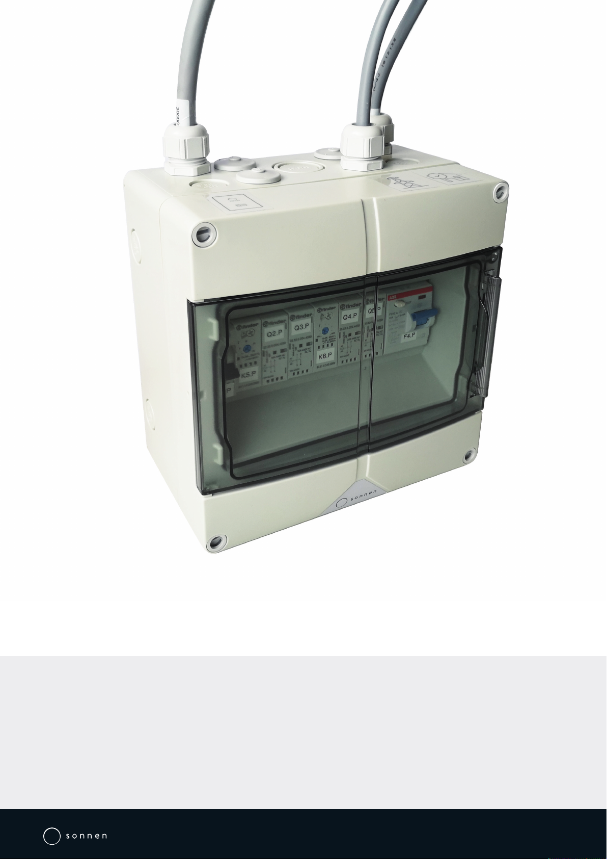
3.2 System components of the sonnenProtect
Test
Test
Illustration1: System components of the sonnenProtect
1 sonnenProtect 4 Line to backup circuit
2 Line from storage system 5 Residual current device (F4.P)
3 Line from electrical distributor 6 Miniature circuit breaker (F3.P)
3.3 Type plate
The type plate is located on the outer surface of the sonnenProtect. The type plate can be
used to uniquely identify the sonnenProtect. The information on the type plate is required
for the safe use of the system and for service matters.
The following information is specified on the type plate:
• Item designation
• Item number
• Technical data
A duplicate of the type plate for the sonnenProtect 2500 must be affixed by the installer
to the storage system (see Attaching type label to storage system [P.19]).

3 | Product description
10 / 28 Installation instructions sonnenProtect 2500
3.4 Symbols on the outside of the sonnenProtect
Symbol Meaning
Warning: electrical voltage.
5 min
Warning: electrical voltage. Wait five minutes after switching off (ca-
pacitor de-energising time).
CE mark. The product meets the requirements of the applicable EU
Directives.
WEEE mark. The product must not be disposed of in household waste,
dispose of it through environmentally friendly collection centres.
Observe the documentation. The documentation contains safety in-
formation.
3.5 Storage and transport
Storage and transport conditions are defined in the product documentation of the storage
system.
Observe the same storage and transport conditions for the sonnenProtect.

Mounting | 4
KD-535 | 1000050 | EN | 02 11 / 28
4 Mounting
4.1 Scope of delivery
Check the following scope of delivery to ensure it is complete.
Test
3
21
4
1 sonnenProtect incl. connection cables (each about 4.75 m)
2 Safety label
3 Installation and operating instructions
4 Type plate sonnenProtect 2500
5 Miniature circuit breaker B20
4.2 Additional parts required
The following components are not included in delivery and must be selected and
ordered by the qualified electrician accordingly:
•Earthing cable (for ‘Connecting earthing cable to storage system [P.18]’)
– Cable cross-section: 10mm² (CU cross-section)
•Miniature circuit breaker (for ‘Positioning components in the electrical distributor
[P.15]’)
– Tripping characteristics: B
– Nominal current: 20A
•Components for forming the backup circuit(s) (for ‘Installing the backup circuit(s)
[P.14]’)
– This includes all electrical lines, necessary circuit breakers and any possibly neces-
sary components such as distributor housings.
4 | Mounting
12 / 28 Installation instructions sonnenProtect 2500
4.3 Selecting the installation location
4.3.1 Requirements for the installation location
Observe the required ambient conditions (see Technical data [P.8]).
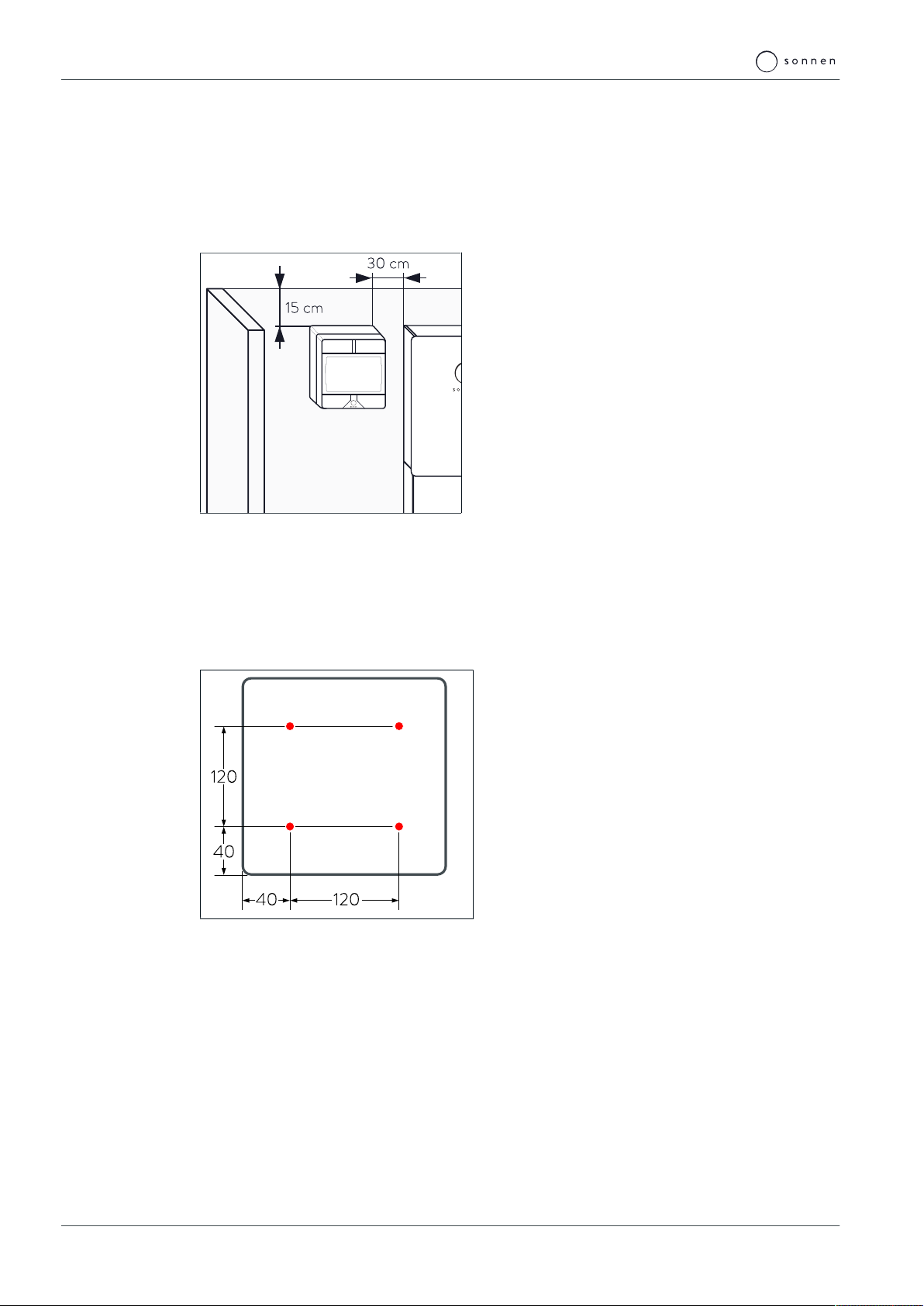
4.3.2 Observe minimum distances
Illustration2: Minimum distances
Observe the specified minimum distances
between the device and the storage system and
neighbouring objects.
Install the sonnenProtect at the same level as
the top edge of the storage system, if possible.
This keeps the cable length as short as possible.
The minimum distances ensure that
• the sonnenProtect can be easily reached and
• there is sufficient space for installation and maintenance work.
4.4 Mounting the sonnenProtect
1610
1532
838,5
Illustration3: Drill template for sonnenProtect
(figure is not to scale - all specifications are in
millimetres)
Drill the holes shown in red in the illustration
on the left.
Secure the sonnenProtect using appropriate
fastening material.

Electrical installation | 5
KD-535 | 1000050 | EN | 02 13 / 28
5 Electrical installation
DANGER Electrical work on the storage system and electrical distributor
Danger to life due to electrocution!
Switch off the storage system to electrically isolate it.
Disconnect the relevant electrical circuits.
Secure against anyone switching on the device again.
Wait five minutes so the capacitors can discharge.
Check that the device is disconnected from the power supply.
Only licensed electricians are permitted to carry out electrical work.
Due to the extension of the storage system hybrid 9.53 by a sonnenProtect
2500, the system is ready for emergency power as well as operation in island-
ing mode. These are functionalities that may need to be specified when regis-
tering a storage system with the distribution system operator (DSO).
This means that under certain circumstances it may be necessary to change in-
formation on the storage system at the DSO or to re-register it.
Recommended procedure for the electrical installation
Carry out the steps in the following order to ensure the smooth electrical installation of
the sonnenProtect:
1. Read sections ‘Electrical consumers in backup operation [P.14]’ and ‘Implementing
the backup circuit(s) [P.14]’ and, together with the operator of the storage system
and the sonnenProtect, define how the backup circuit or circuits are to be set up. The
on-site circumstances must always be taken into account during this process, because
with electrical installations where there are few separate circuits, it can be difficult to
integrate all of the desired electrical consumers in the backup circuit or to integrate
only the consumers which should be supplied with backup power.
2. Carry out the necessary revision work on the distributor in the building. It is essential to
ensure that all electrical cables meet local and national regulations in terms of their di-
mensioning.
3. If the backup circuit or circuits are installed accordingly, the sonnenProtect can be
connected and the necessary additions can be made to the storage system (see the
following sections).
4. When all steps have been implemented and the electrical installation is complete, con-
tinue with section ‘Commissioning [P.21]’.

5 | Electrical installation
14 / 28 Installation instructions sonnenProtect 2500
5.1 Installing the backup circuit(s)
5.1.1 Electrical consumers in backup operation
Before installation, the installer must explain or clarify with the operator the following
points:
• Backup operation does not offer the same output as grid operation.
• Three-phase current is not available during backup operation (as only one phase is sup-
plied with power).
•Which electrical consumers should be supplied with power in backup operation? The
current paths in the building network must be installed in such a way that the consumers
which are relevant in the event of a grid outage are connected to an independent circuit
(backup circuit). The electrical consumers which are crucial for the operator in backup
operation are relevant here. Different consumers which may be important during a grid
outage are specified in the sample calculation presented below.
•How much capacity of the storage system should be reserved as an backup buffer? The
following example, in which a utility room and other important functions within a single-
family home are to be supplied with power, can be used to determine this. This example
is based on a grid outage lasting one hour (the individual power consumption values are
estimated values).
Electrical consumer Power consumption
[kW]
Active during grid
outage
[h]
Electrical work
[kWh]
Lighting 0.5 1 0.5
Freezer 0.6 0.25 0.15
Heating 0.7 0.25 0.175
Router, telephone 0.01 1 0.01
Refrigerator 0.6 0.25 0.15
Alarm system, grid-connected
smoke detector
0.05 1 0.05
Total 1.04
In this example, the total power requirement for a grid outage lasting one hour is approx.
1.1kWh, which must be covered in order to maintain the function of all of the listed con-
sumers.
Use this calculation to determine with the operator which backup buffer should be set,
taking the total capacity of the storage system and other requirements (e.g. from
sonnenFlat tariff) into account (see Setting the backup buffer [P.21]).
5.1.2 Implementing the backup circuit(s)
Basics for the formation of the backup circuits:
• For systems with backup power capability, the power distribution must be separated into
backup power authorised and not backup power authorised parts.
• All components within the backup power authorised part must be clearly identified by
lettering (or graphic symbols).
At any time observe further local and national requirements and guidelines regarding
backup power supply!

Electrical installation | 5
KD-535 | 1000050 | EN | 02 15 / 28
When undertaking electrical work on the distributor in the building, the following must be
taken into account, among other things:
1. How is the wiring set up to the desired backup consumers?
– Is independent wiring already in place?
– Do the existing circuits include electrical consumers that should not be supplied
with power in backup operation?
– Can the existing wiring be split?
– If the circuits cannot be split, the connected wattage of the consumers which
should not be supplied with backup power needs to be taken into account. If loads
are too high, the circuit breaker for the sonnenProtect will trip, and then none of
the electrical consumers in the backup circuit will be supplied with power.
2. Can the electrical distributor in the building be adapted to suit the new circumstances?
– Is there enough space to install the necessary circuit breakers and other compon-
ents in the distributor?
5.2 Positioning components in the electrical distributor
The following components must be installed in the electrical distributor for the
sonnenProtect:
•Miniature circuit breaker (MCB) | typeB | 20A
A miniature circuit breaker with typeB tripping characteristics and a nominal current of
20A must be installed upstream of the input for the sonnenProtect.
5.3 Wiring components in the electrical distributor
Prerequisite:
üThe backup circuit has been properly installed. The information in section Installing the
backup circuit(s) [P.14] was observed at all times.
Connect the sonnenProtect and the other components in the electrical distributor as
shown in the following figure.
Note:
• The figures ‘Circuit diagram overview - electrical connection at single-phase mains
[P.16]‘ and ‘Circuit diagram overview - electrical connection at three-phase mains
[P.17]’ show the installation of a sonnenBatterie hybrid 9.53 as an example, which has
been installed in a single- or three-phase network in accordance with the specifications
in the product documentation and to which a sonnenProtect has been added (grey
marked area).
5 | Electrical installation
16 / 28 Installation instructions sonnenProtect 2500
kWh
NL1 L2 L3
A1 A2
3
1
2
1 2 3
4
L1
L2
L3
N
PE
3
PE'
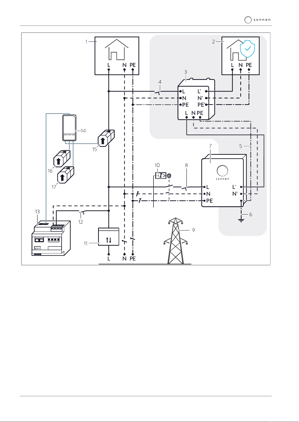
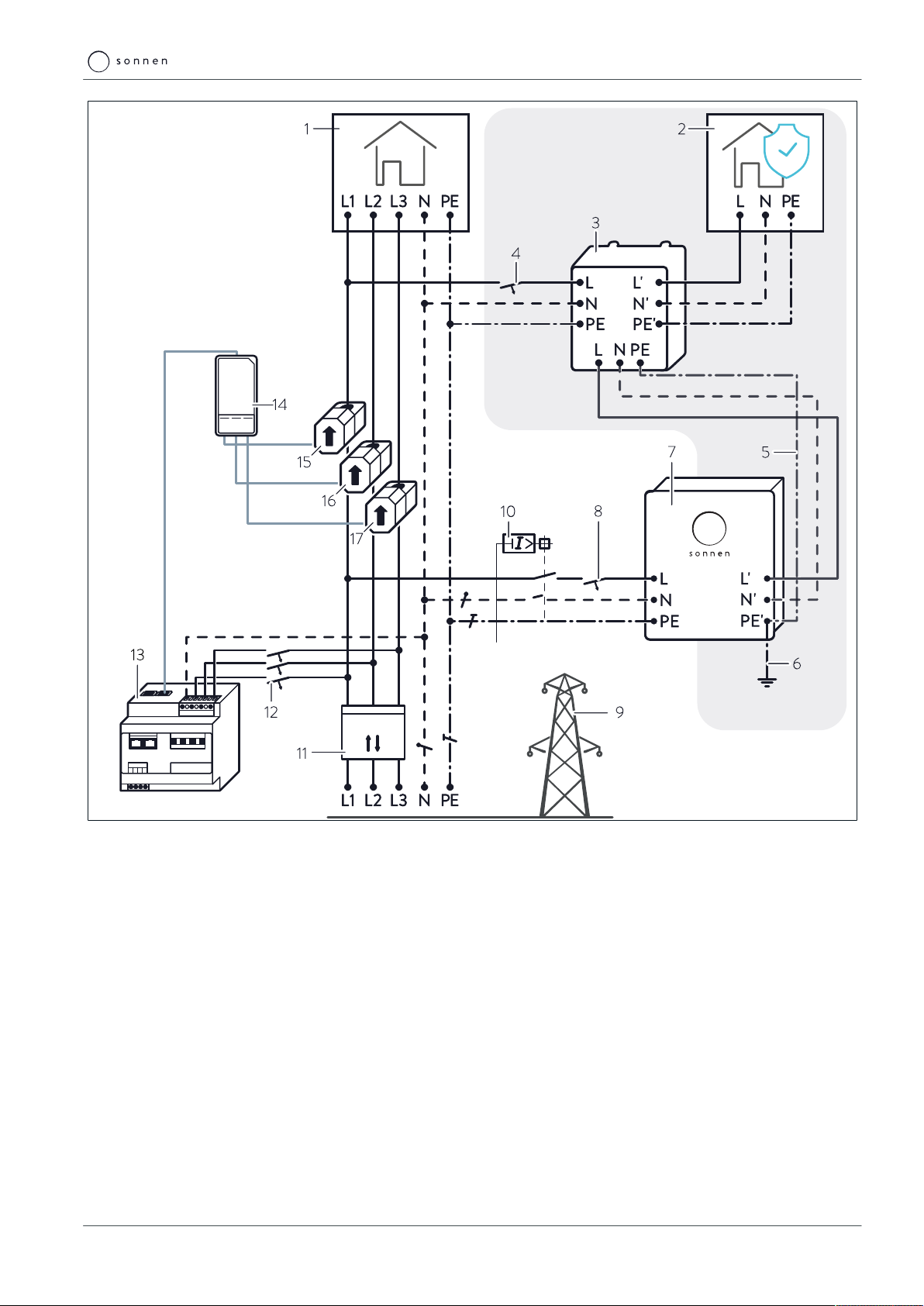
Illustration4: Circuit diagram overview - electrical connection at single-phase mains
1 Consumers in building 10 RCD | Type B | 30 mA
2 Consumers in backup circuit 11 Bidirectional counter
3 sonnenProtect with integrated RCD 12 Power meter Miniature circuit breaker
4 Miniature circuit breaker | Type B | 20A 13 Power meter
5 Line from storage system 14 Transformer interface consumption (A2)
6 Earth connection 15 Current transformer for consumption - L1
7 Storage system 16 Current transformer for consumption - L2
8 Storage system Miniature circuit breaker 17 Current transformer for consumption - L3
9 Public electrical mains
Electrical installation | 5
KD-535 | 1000050 | EN | 02 17 / 28
kWh 3~
NL1 L2 L3
A1 A2
3
1
2
1 2 3
4
L1
L2
L3
N
PE
3
Illustration5: Circuit diagram overview - electrical connection at three-phase mains
1 Consumers in building 10 RCD | Type B | 30 mA
2 Consumers in backup circuit 11 Bidirectional counter
3 sonnenProtect with integrated RCD 12 Power meter Miniature circuit breaker
4 Miniature circuit breaker | Type B | 20A 13 Power meter
5 Line from storage system 14 Transformer interface consumption (A2)
6 Earth connection 15 Current transformer for consumption - L1
7 Storage system 16 Current transformer for consumption - L2
8 Storage system Miniature circuit breaker 17 Current transformer for consumption - L3
9 Public electrical mains

5 | Electrical installation
18 / 28 Installation instructions sonnenProtect 2500
5.4 Connecting earthing cable to storage system
The output circuit of the storage system inverter is floating.
• An earthing conductor with a cross-section of 10mm² (CU cross-section) must be in-
stalled between the storage system and the main earthing terminal.
60°C
Illustration6: Connecting earthing line to storage system
Direct a corresponding earthing cable through the designated cable gland(1) into the
storage system.
Connect the earthing cable(2) to terminal5 of terminal stripX1.
Connect the earthing cable to the main earthing terminal of the building.
5.5 Connecting sonnenProtect to storage system
Connect the line of the sonnenProtect to the socket of the storage system (2) using
the pre-mounted plug (1).
Illustration7: Connecting sonnneProtect and storage system

Electrical installation | 5
KD-535 | 1000050 | EN | 02 19 / 28
5.6 Attaching safety label to the distributor
DANGER Electrical installation remains live in event of grid outage
Danger to life due to electrocution!
To warn electricians:
Attach the safety label shown below (included in scope of delivery) to the
relevant electrical distributor.
Illustration8: Label for attachment to the electrical distributor
5.7 Attaching type label to storage system
As the sonnenProtect 2500 constitutes an add-on to the storage system, a du-
plicate of the type plate for the sonnenProtect must be affixed to the storage
system.

5 | Electrical installation
20 / 28 Installation instructions sonnenProtect 2500
Illustration9: Affixing an additional type plate
to the storage system
Affix the type plate for the sonnenProtect
2500, which is included in delivery, to the out-
side of the storage system next to the type
plate for the storage system itself.
Other manuals for sonnenProtect 2500
3
This manual suits for next models
1
Table of contents
Other Sonnen Power Distribution Unit manuals


Popular Power Distribution Unit manuals by other brands

Synergy Global Technology
Synergy Global Technology RA5014-515-15A-515 installation manual

ATEN
ATEN ALTUSEN PE6108 user manual

eltherm
eltherm ELAK-Ex-R Installation and operations

POINT POD
POINT POD Compact V1 user manual

S&C
S&C VacuFuse Installation and operation

CyberPower
CyberPower PDU20BHVT8R user manual


