Synergy RA5204-L520-30A-L143 User manual

Rack Power Distribution Unit
28-foot NEMA L14-30 power cord
Four 20-amp circuit breakers
AP7580: Four NEMA L5-20 outlets
AP7581: Four NEMA L6-20 outlets
28-foot NEMA L14-30 power cord
Two 20-amp circuit breakers
Twelve NEMA 5-20 outlets
RA5204-L520-30A-L143 RA5204-L620-30A-L143
RA5212-520-30A-L143

2 Rack Power Distribution Unit
28-foot NEMA L14-30 power cord
AP7583: Four NEMA L5-30 outlets
AP7584: Four NEMA L6-30 outlets
RA5204-L530-30A-L143 RA5204-L630-30A-L143

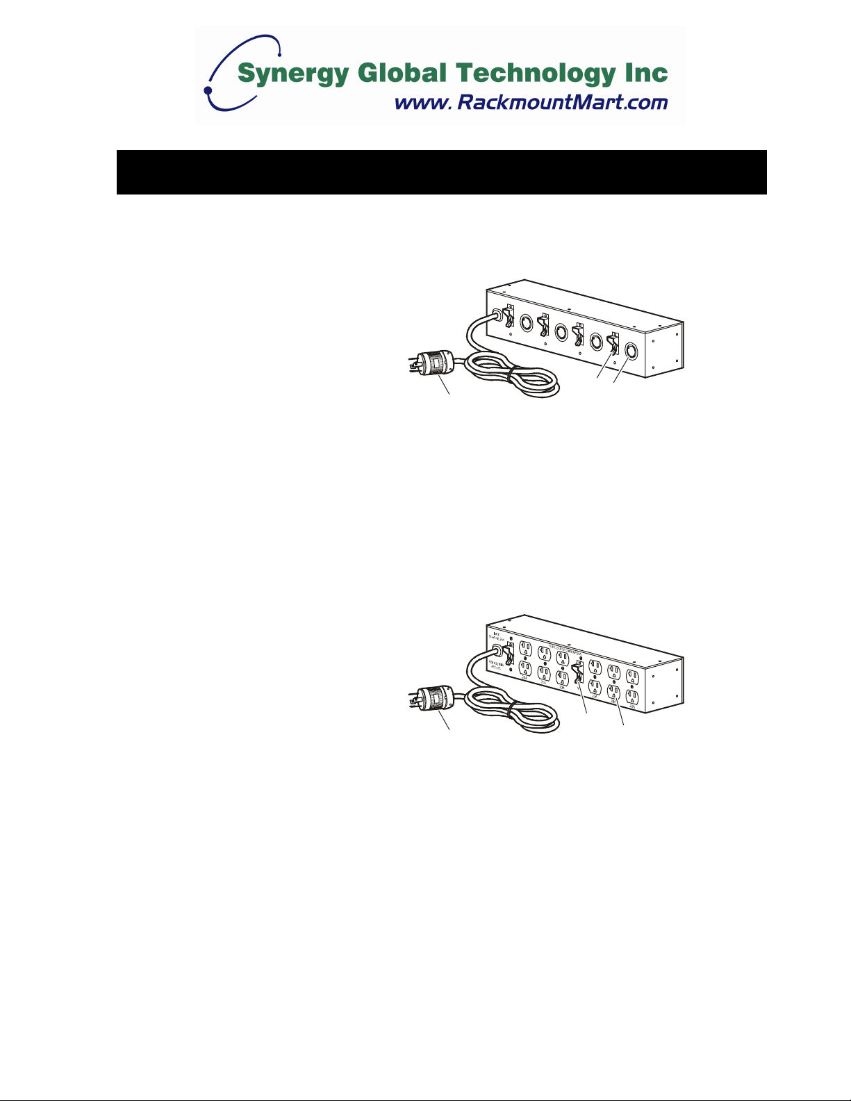
Rack Power Distribution Unit 3
Safety and Grounding
Read the following information before installing or operating your
Power Distribution Unit (PDU):
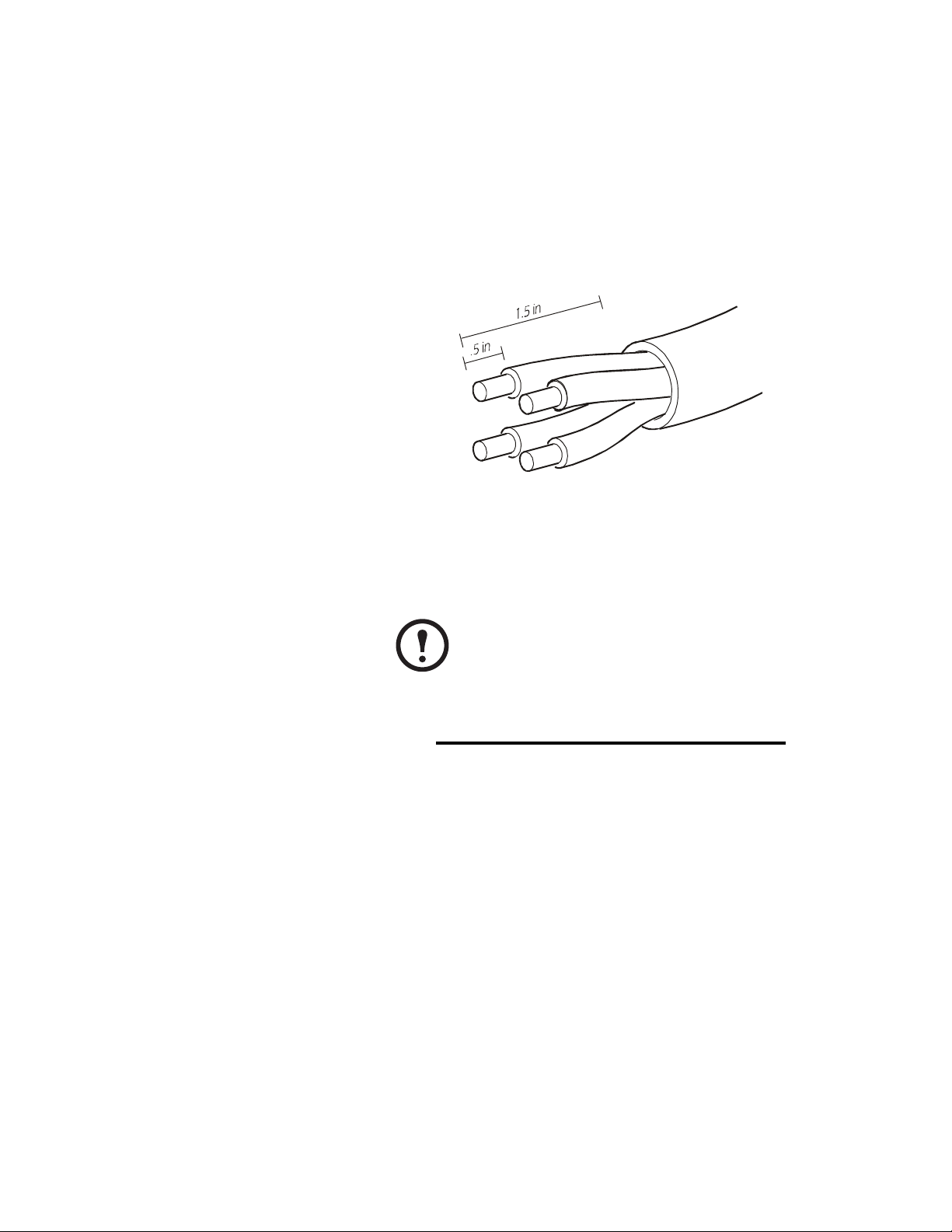
• The PDU is intended only for use with four-wire grounded
connections on APC Uninterruptible Power Supplies (UPSs). Do
not plug the PDU into an electrical outlet or other device.
• This PDU is intended for indoor use only.
• Do not install this PDU where excessive moisture or heat is
present.
• Never install any wiring, equipment, or PDUs during a lightning
storm.
• Do not use extension cords or adapters with this PDU.
• Do not work alone under hazardous conditions.
• Check that the power cord, plug, and socket are in good condition.
• Disconnect the PDU from the power outlet before you install or
connect equipment to reduce the risk of electric shock when you
cannot verify grounding. Reconnect the PDU to the power outlet
only after you make all connections.
• Install the PDU so that the power plug may be disconnected for
service.
• Install the PDU so that there is not an uneven mechanical load.
• Follow the nameplate ratings when connecting equipment to the
supply circuit. Do not overload the circuits. An overload condition
could put your over-current protection at risk or cause problems
with your supply wiring.
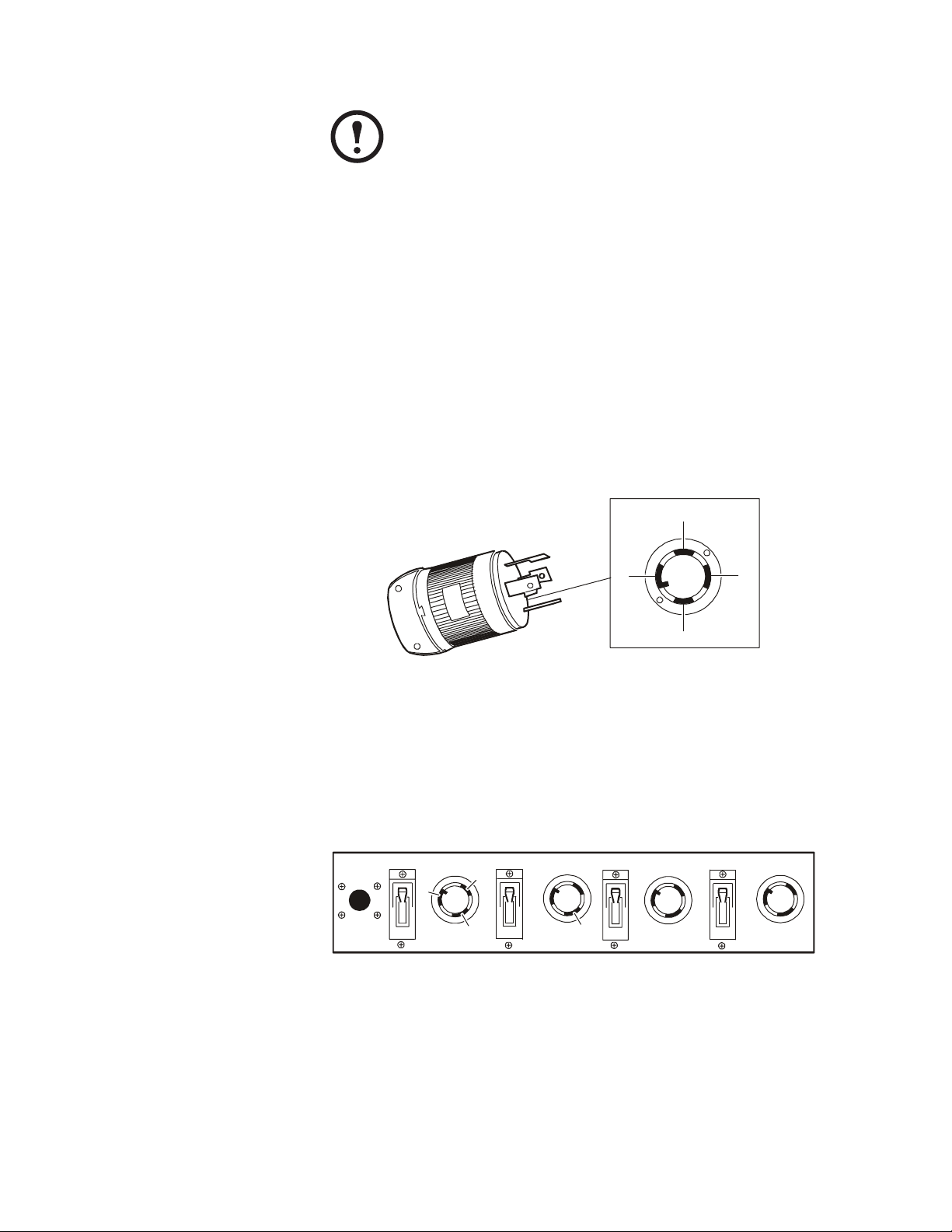
C
aut
i
on
Risk of electrical shock. Use only the supplied hardware to
attach the mounting brackets.
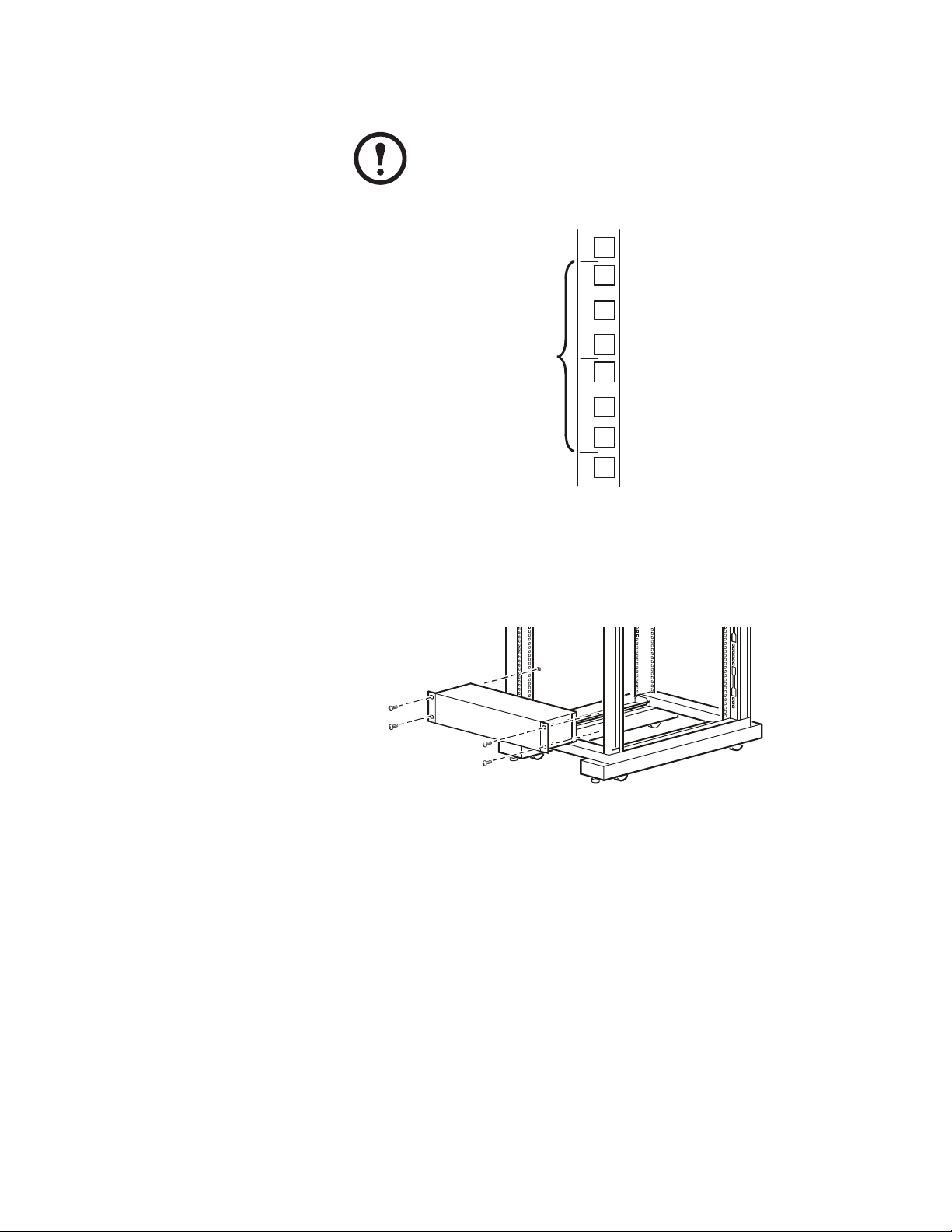
Note
The Rack PDUs are to be used only with InfraStruXure
Type A systems.

4 Rack Power Distribution Unit
How to Shorten the Power Cord
Plug layout
Remove the plug 1. Loosen, but do not remove, the four captive screws from the plug
face until it is detatched from the plug.
2. Loosen, but do not remove, the four screws from the sides of the
plug until the cord easily slides in and out.
3. Slide the plug case down the cord to your desired length.
4. Loosen, but do not remove, all four terminal screws until you can
remove all four wires from the plug. Set the plug face aside for
later use.
Warn
i
ng
Only certified electricians can perform the following
procedure.
Cord sleeve
Strain relief
Plug case
Plug face
Note
The cord must remain at least 4.9 feet (58.8 inches) long.

How to Shorten the Power Cord
Rack Power Distribution Unit 5
Cut the cord 1. Cut the outer cord sleeve to the desired length. Be careful not to cut
through the four wire bundles. The cord must remain at least
4.9 feet (58.8 inches) long from unit to end. Remove the cut sleeve
from the wire bundles.
2. Cut each wire bundle, making sure each is approximately 1.5
inches from the end of the cord sleeve.
3. Strip approximately 0.5 inches of insulation from each wire
bundle.
Reassemble the plug 1. Twist together any loose wires.
2. Fully insert each wire into its coordinating terminal on the plug
face before you tighten the terminal screw.
3. Tighten the terminal screws to a minimum torque of 18 inch-
pounds.
4. Slide the plastic plug case back around the face of the plug. Align
the tab on the case with the corresponding opening on the plug
face. Secure the case by tightening two of the screws in the side of
the case to a minimum torque of 10 inch-pounds.
5. Reattach the strain relief to the plug, using the remaining two
screws. Tighten the screws to a torque of 16 to 20 inch-pounds.
Note
Insert only the bare copper wires into the terminals.
Do not tin the wires that hold the strands together.
Wire color Terminal
Red Terminal marked “Y”
Black Terminal marked “X”
Green Ground pin, has a green screw
White No markings, has a silver prong

How to Shorten the Power Cord
6 Rack Power Distribution Unit
Test the plug for
Use a multimeter and the following graphics to verify continuity
between the test points .
Continuity is achieved with a measurement of less than or equal to 1 Ohm.
Use the probes of the multimeter to verify continuity between the
following points on the plug prongs and the slots on the outlets:
• Ground (J) on the plug and Ground (J) on the outlet
• Neutral (Q) on the plug and Neutral (Q) on the outlet
•X(
[) on the plug and X ([) on the outlet
•Y(
\) on the plug and Y (\) on the outlet
Verify that there is no continuity among any of the four prongs on the
plug.
View of the plug face:
View of the outlets:
Note
verify that all circuit breakers are in the ON position.
JGround terminal
\Y terminal
QNeutral terminal (Silver)
[X terminal
JGround connection
QNeutral connection
[X connection
\Y connection
J
[
Q
\
ON ON
ON ON
J
Q
\
[
RA5204-L520-30A-L143
RA5204-L530-30A-L143
For RA5204-L520-30A-L143

How to Shorten the Power Cord
Rack Power Distribution Unit 7
Test the plug for
Use a multimeter and the following graphics to verify continuity
between the test points.
Continuity is achieved with a measurement of less than or equal to 1 Ohm.
Use the probes of the multimeter to verify continuity between the
following points on the plug prongs and the slots on the outlets:
•X(
[) on the plug and X ([) on the outlet
•Y(
\) on the plug and Y (\) on the outlet
• Ground (J) on the plug and Ground (J) on the outlet
Verify that there is no continuity among any of the four prongs on the
plug.
View of the plug face:
View of the outlets:
Note
verify that all circuit breakers are in the ON position.
JGround terminal
\Y terminal
QNeutral terminal (Silver)
[X terminal
JGround connection
\Y connection
[X connection
J
[
Q
\
ON ON
ON ON
J
[
\
RA5204-L620-30A-L143
RA5204-L630-30A-L143
For RA5204-L620-30A-L143

How to Shorten the Power Cord
8 Rack Power Distribution Unit
Test the plug for
Use a multimeter and the following graphics to verify continuity
between the test points. Continuity is achieved with a
measurement of less than or equal to 1 Ohm.
Use the probes of the multimeter to verify continuity between the
following points on the plug prongs and the slots on the outlets:
• Ground (J) on the plug and Ground (J) on the outlet
• Neutral (Q) on the plug and Neutral (Q) on the outlet
•X(
[) on the plug and X ([) on the outlet
•Y(
\) on the plug and Y (\) on the outlet
Verify that there is no continuity among any of the four prongs on the
plug.
View of the plug face:
View of the outlets:
Note
Verify that all circuit breakers are in the ON position.
JGround terminal
\Y terminal
QNeutral terminal (Silver)
[X terminal
JGround connection
QNeutral connection
[X connection
\Y connection
J
[
Q
\
ON ON
[QJ
\
RA5212-520-30A-L143

Rack Power Distribution Unit 9
How to Install the PDU
Mounting options Install the PDU in the bottom 2U of a NetShelter®or any standard
19-inch EIA-310-D rack or enclosure, using the mounting brackets
(provided).
Bracket-mounting 1. Attach the mounting brackets to the PDU, using four flat-head
screws per bracket (provided).
- To mount the PDU with the outlets facing out of the rack:
- To mount the PDU with the outlets facing the top of the rack:
Note
The PDU can be installed in one of two ways, with the outlets
facing out of the rack or toward the roof of the rack.
Note
The PDU is intended only for use with an APC UPS. Do not
plug it into an electrical outlet or another device.

How to Install the PDU
10 Rack Power Distribution Unit
2. Choose a location for the PDU.
a. Insert a caged nut (provided with the enclosure) above and
below a notched hole on each vertical mounting rail in your
chosen location.
b. Align the mounting holes of the brackets with the installed
caged nuts. Insert and tighten the screws.
Connect to an APC UPS 1. Route the power cord through one of the slots on the roof of the
enclosure.
2. If necessary, route the PDU cord across a ladder connected to the
enclosure to connect to an UPS.
3. Plug the PDU into the L14 outlet on the rear of the UPS.
Note
The PDU occupies two U-spaces. The numbers on the
enclosure’s vertical rail denote the middle of a U-space.
2U

Rack Power Distribution Unit 11
Specifications
Electrical
Nominal input voltage 120 or 208 V
Input frequency 50 or 60 Hz
Input connectors NEMA L14-30 plug
Output connectors RA5204-L520-30A-L143: Four NEMA L5-20 outlets
RA5204-L620-30A-L143: Four NEMA L6-20 outlets
RA5212-520-30A-L143: Twelve NEMA 5-20 outlets
RA5204-L530-30A-L143: Four NEMA L5-30 outlets
RA5204-L630-30A-L143: Four NEMA L6-30 outlets
Maximum total current draw 24 A
Physical
Size (H × W × D) 3.50 ×17.20×3.50 in
(8.89×43.69×8.89 cm)
Weight 14.0 lb (6.4 kg)
Environmental
Elevation (above MSL)
Operating
Storage
0–10,000 ft (0–3000 m)
0–50,000 ft (0–15 000 m)
Temperature
Operating
Storage
0 to 45° C (32 to 115° F)
–25 to 65° C (–13 to 149° F)
Humidity
Operating
Storage
0–95% RH Non-condensing
Compliance
Safety verification UL, cUL
This manual suits for next models
1
Table of contents
Popular Power Distribution Unit manuals by other brands

Walther Systemtechnik
Walther Systemtechnik WMV-03-K-14-14-01 installation manual

Tripp Lite
Tripp Lite SUPDM Series owner's manual

Securitytronix
Securitytronix ST-PBX9/10A-PTC installation manual

Tripp Lite
Tripp Lite PDUMNH15 owner's manual

Sel
Sel TPS 12kv manual

Tripp Lite
Tripp Lite SUPDMB710 Specification sheet