10 S&C Instruction Sheet 465-500
Installation
Installing a VacuFuse Self-Resetting
Interrupter into the Cutout Mounting
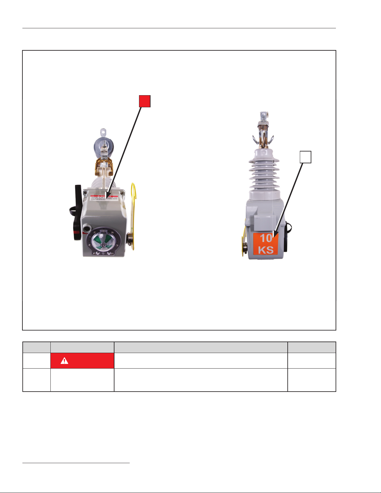
WARNING
Provide training to line crews on the use of both a
hotstick and an extendostick before installing or
operating the VacuFuse Self-Resetting Interrupter.
The VacuFuse interrupter is different from other
cutout-mounted devices. Failure to properly handle
a VacuFuse interrupter with a hotstick and/or an
extendostick may lead to serious injury or death.
STEP 1. If using an existing S&C cutout mounting
or other approved cutout mounting:Visually
inspect the cutout mounting for damage or
excessive wear, particularly in the upper and
lower contact areas. If ANY damage is visible,
replace the cutout mounting before proceeding.
DO NOT install and/or energize a VacuFuse
Self-Resetting Interrupter into a damaged
cutout mounting.
If installing in a new S&C cutout mount-
ing: For overhead pole-top style VacuFuse Self-
Resetting Interrupters, attach the mounting to
its mounting bracket, as illustrated in Figure 4.
A mounting bracket, suitable for crossarm, pole,
or wall mounting, is furnished only if specified
through the addition of catalog number suffix
“-B” or “-C” to the VacuFuse interrupter catalog
number.
Note the placement of the external-tooth
lockwasher between the mounting bracket and
the center insert of the mounting. Pivot the
mounting bracket to a position that will provide
maximum ease of operation, and then securely
tighten the carriage-bolt nut.
STEP 2. Make the electrical connections to the cutout
mounting. If aluminum conductors are used, be
sure to wire-brush them and apply a coating of
oxidation inhibitor before inserting them into
the connectors.
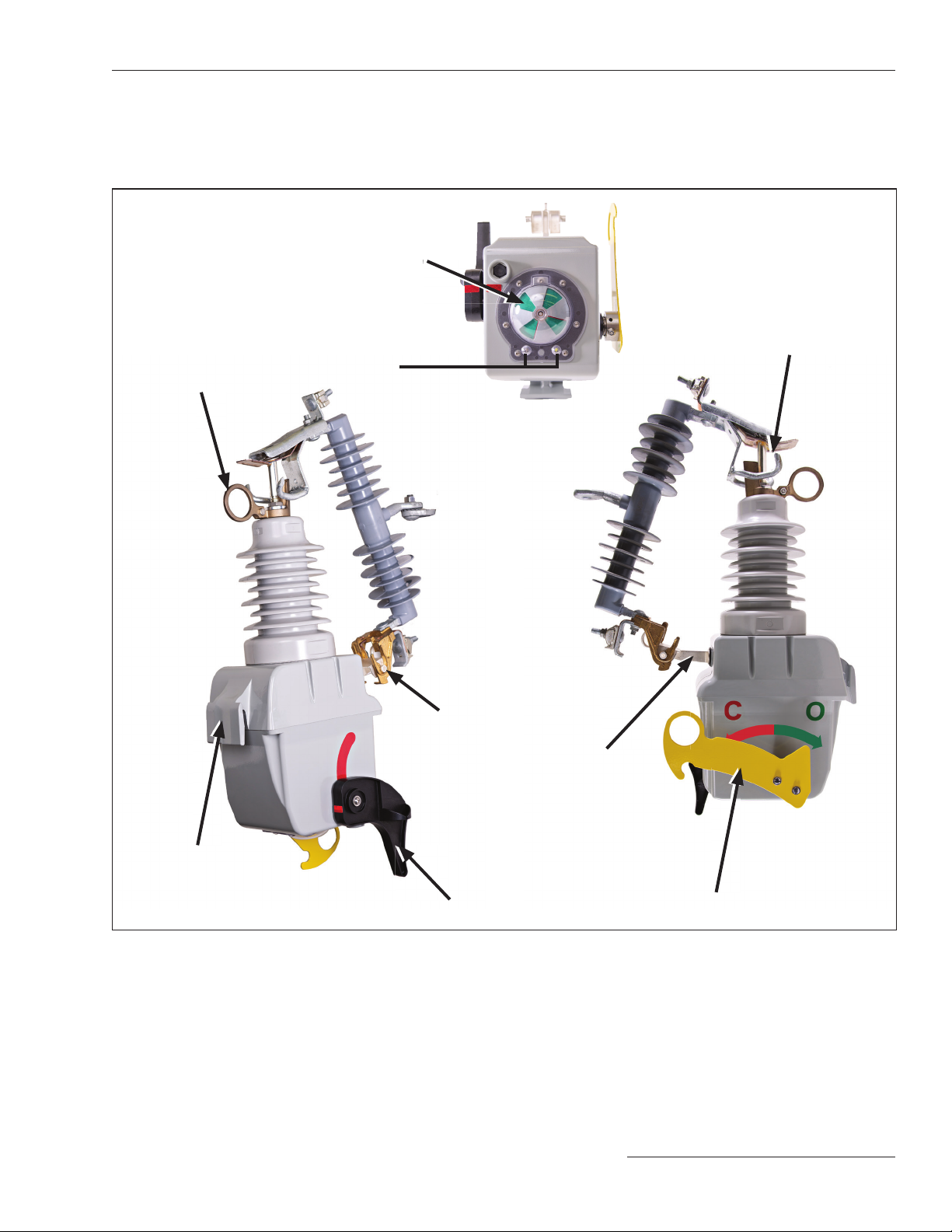
STEP 3. Installation Using Insulated Gloves: With
the OPEN/CLOSE lever in the Open position,
insert the VacuFuse Self-Resetting Interrupter
into a 125-kV BIL- or a 150-kV BIL-rated
mounting with gloved hands, as shown in
Figures 5 and 6. Guide the trunnion into the
hinge of the cutout mounting, as shown in
Figure 6.
Figure 6. Guiding the trunnion into the hinge of the cutout
mounting using gloved hands.
Figure 5. Bringing the trunnion close to the hinge of the
cutout mounting.
Carriage-bolt
Carriage bolt nut
Lockwasher
Mounting
bracket Overhead pole-
top mounting
center insert
External
tooth
lockwasher
Figure 4. Attaching an overhead pole-top style VacuFuse
interrupter cutout mounting to the mounting bracket.
Trunnion