Sonosax SX-ST User manual

PROFESSIONAL
MIXING CONSOLE
SONOSAX
SX-ST / SX-VT
User Manual
Audio equipements manufacturer
SONOSAX SAS S.A.
Ch. de la Naz 38
1052 Le Mont s/Lausanne
SUISSE
Tél: +41 21 651 0101
Fax: +41 21 651 0109
Web: www.sonosax.ch
Version: June 2010

Mode d’emploi SONOSAX SX-ST / SX-VT Page 2 de 73
TABLE OF CONTENT
1. INTRODUCTION .................................................................................................................................................. 5
1.1 Safety Instructions ............................................................................................................................................. 5
2. FIELDS OF APPLICATIONS .............................................................................................................................. 6
2.1 MAIN FEATURES ................................................................................................................................................ 6
2.2 Versions, options and accessories................................................................................................................... 7
2.2.1 SONOSAX SX-ST ................................................................................................................................................ 7
2.2.2 SONOSAX SX-VT ................................................................................................................................................ 7
2.2.3 VCA Mic/Line Input: version with Compressor and optional VCA groups .............................................................8
2.2.4 Stereo Line Input: available with or w/o VCA groups ............................................................................................ 8
2.2.5 Digital Module: Analogue to Digital Converter ( Option ) ...................................................................................... 8
2.2.6 Digital Module: 8 track Internal Recorder ( Option ).............................................................................................. 8
2.2.7 Boom Box ( accessory )........................................................................................................................................ 8
3. POWERING.......................................................................................................................................................... 9
3.1 Powering from batteries..................................................................................................................................... 9
3.1.1 Removing the battery compartment...................................................................................................................... 9
3.1.2 Opening the battery compartment ...................................................................................................................... 10
3.1.3 Closing the battery compartment........................................................................................................................ 10
3.1.4 Battery Test ........................................................................................................................................................ 11
3.1.5 Low Battery alarm [LO BATT]............................................................................................................................. 11
3.1.6 Battery charger (option for SX-ST Series only)................................................................................................... 11
3.2 External DC supply ( SX-ST only ) .................................................................................................................. 11
3.2.1 Automatic changeover of the DC power source ................................................................................................. 11
3.3 Main power supply ( SX-VT only )................................................................................................................... 12
4. MIC/LINE INPUT MODULE................................................................................................................................ 13
4.1.1 Input selector [ XLR – IN B ] ............................................................................................................................... 14
4.1.2 Direct channel Output [ LINE OUT ] ................................................................................................................... 14
4.1.3 Phantom power [ DYN - 48V ] ........................................................................................................................... 14
4.1.4 Phase reversal [ Ø]............................................................................................................................................ 14
4.1.5 Input GAIN setting [ GAIN ] ................................................................................................................................ 15
4.1.6 Limiter (non-VCA version) ................................................................................................................................. 15
4.2 Filtrer and Equalizer ......................................................................................................................................... 15
4.2.1 Sweep Low Frequencies Cut [ LF CUT ] ............................................................................................................ 15
4.2.2 3 bands semi-parametric Equalizer [ EQ ] .......................................................................................................... 16
4.3 Mix busses assignments [ 1 to 8 ]................................................................................................................... 17
4.3.1 Panoramic Potentiometer [ PAN ]....................................................................................................................... 17
4.4 Auxiliary Sends [AUX 1 to 4] ........................................................................................................................... 18
4.4.1 AUX busses assignment [ PRE–OFF–POST ] ................................................................................................... 18
4.4.2 Channel fader ..................................................................................................................................................... 18
4.4.3 Level switch [12 - 24] .......................................................................................................................................... 18
4.4.4 Dual Peak Level Meters...................................................................................................................................... 18
4.4.5 On / Mute Key [ ON ] .......................................................................................................................................... 19
4.4.6 PFL/AFL Pre-Listening [ P/A ]............................................................................................................................ 19
4.4.7 Channel power on switch [PWR –ON])............................................................................................................... 19
4.5 VCA groups selector (modules with VCA only) ............................................................................................. 20
4.6 Compressor (modules with VCA only) ........................................................................................................... 20
4.6.1 Threshold............................................................................................................................................................ 20
4.6.2 Ratio ................................................................................................................................................................... 20
4.7 On Air Signalling (SX-VT only) ........................................................................................................................ 20
4.8 Fonction MUTE ................................................................................................................................................. 20

Mode d’emploi SONOSAX SX-ST / SX-VT Page 3 de 73
5. STEREO LINE INPUT MODULE ....................................................................................................................... 21
5.1 Left & Right gain controls................................................................................................................................ 22
5.2 Selector [ MONO ]............................................................................................................................................. 22
5.3 Stereo Equalizer [ EQ ]..................................................................................................................................... 22
5.4 Auxiliary Sends [AUX 1] to [AUX 4] ................................................................................................................ 22
5.4.1 Auxiliary routing switches [PRE-OFF-POST]...................................................................................................... 22
5.5 Dual Peak level meter....................................................................................................................................... 23
5.6 Assignment to mix busses 1/2 to 7/8............................................................................................................. 23
5.6.1 Channel Fader.................................................................................................................................................... 23
5.6.2 Left – Right Balance [ BAL ]................................................................................................................................ 23
5.6.3 On / Mute Key [ ON ] .......................................................................................................................................... 24
5.7 Fader Start [ REMOTE ]................................................................................................................................... 24
5.8 PFL/AFL Pre-Listening [ P/A ]......................................................................................................................... 24
5.9 VCA groups selector (optional on SX-VT Series only).................................................................................. 24
6. MASTER AND MONITORING MODULE........................................................................................................... 25
6.1.1 METERING......................................................................................................................................................... 26
6.1.2 Meter's operating mode [ ST-M-Low Batt ] ......................................................................................................... 26
6.1.3 Meter's backlight [ BACK ] .................................................................................................................................. 26
6.1.4 Led's operating mode [ LEDS ] ........................................................................................................................... 26
6.1.5 Signalling Leds [ ON AIR ] and [ MUTE ] (SX-VT only) .................................................................................... 26
6.2 Talkback/SLATE and Oscillator....................................................................................................................... 27
6.2.1 Source Selector [ MIC-OSC-FIX ]...................................................................................................................... 27
6.3 Pre listening Selector [ PFL-AFL-SOLO ] ....................................................................................................... 27
6.3.1 P/A operating mode [ Normal-Reset ]................................................................................................................. 27
6.4 Powering ON/OFF............................................................................................................................................. 27
6.5 Return lines 1 to 8 [ RETURN ] ........................................................................................................................ 28
6.5.1 Return's Master Level......................................................................................................................................... 28
6.5.2 Return's Pre-Listening [ P/A RET ] ..................................................................................................................... 28
6.6 MONITORING .................................................................................................................................................... 28
6.6.1 Monitor Source Selector ..................................................................................................................................... 28
6.6.2 Monitor Mode selector ........................................................................................................................................ 28
6.6.3 Headphone volume [ PHONE 1 ] to [ PHONE 3 ] ............................................................................................... 29
6.7 Communication and Private Lines [ COM – PL1 – PL2 ] .............................................................................. 29
6.7.1 Comm. Monitor Attenuation ................................................................................................................................ 29
6.7.2 [ Mic 1 ] to [ Mic 3 ] ............................................................................................................................................. 29
6.7.3 Side Tone ........................................................................................................................................................... 29
6.8 MASTER SECTION ........................................................................................................................................... 30
6.8.1 GROUP Masters................................................................................................................................................. 30
6.8.2 AUX Masters ...................................................................................................................................................... 30
6.8.3 Modulomètre à 5 Leds ........................................................................................................................................ 30
6.8.4 Key [ P/A ] .......................................................................................................................................................... 31
6.8.5 Commutateurs [ Talkback-Off-Return ]............................................................................................................... 31

Mode d’emploi SONOSAX SX-ST / SX-VT Page 4 de 73
7. DIGITAL MODULE: A/D CONVERTER & INTERNAL 8 TRACKS RECORDER ............................................ 32
7.1 A/D Converter ................................................................................................................................................... 33
7.1.1 Sourcing selector [IN 1 MIX] to [IN 8 MIX] .......................................................................................................... 33
7.1.2 Red led indicator [ L/O ]...................................................................................................................................... 33
7.1.3 Protection Limiter's [ LIMITERS ]........................................................................................................................ 33
7.1.4 Sampling frequencies ......................................................................................................................................... 33
7.1.5 Clocking and Sync.............................................................................................................................................. 34
8. INTERNAL RECORDER.................................................................................................................................... 35
8.1 CONNECTIONS ................................................................................................................................................. 35
8.1.1 Port USB 2.0....................................................................................................................................................... 35
8.1.2 Remote Connector [ REMOTE ] ......................................................................................................................... 35
8.1.3 Time Code Connector [ TC ]............................................................................................................................... 35
8.1.4 Sync Connector [ VIDEO IN ] ............................................................................................................................. 35
8.2 PRINCIPLE OF OPERATION ............................................................................................................................ 36
8.2.1 User Interfaces ................................................................................................................................................... 36
8.2.2 ARCHITECTURE - Audio path ........................................................................................................................... 38
8.3 TRACKS MONITORING .................................................................................................................................... 39
8.3.1 Monitoring Level ................................................................................................................................................. 39
8.3.2 Solo Monitoring................................................................................................................................................... 40
8.4 MENUS CONTEXTUELS................................................................................................................................... 41
8.5 MONITORING .................................................................................................................................................... 42
8.6 LAST TAKE ....................................................................................................................................................... 43
8.6.1 PLAYER Mode ................................................................................................................................................... 44
8.6.2 SEARCH mode................................................................................................................................................... 45
8.6.3 Contextual menu in mode [PLAYER].................................................................................................................. 46
8.7 Unit STATUS ..................................................................................................................................................... 46
8.8 SETUP (Configuration's Menus)...................................................................................................................... 48
8.8.1 Tree structure of the "SETUP" menus ................................................................................................................ 49
8.8.2 ROUTING SETTING .......................................................................................................................................... 50
8.8.3 RECORD SETTINGS ......................................................................................................................................... 51
8.8.4 TIME CODE SETTINGS..................................................................................................................................... 54
8.8.5 MODULOMETERS............................................................................................................................................. 55
8.8.6 USER SETTINGS............................................................................................................................................... 55
8.8.7 SYSTEM SETTINGS.......................................................................................................................................... 56
8.8.8 MISC (Miscellaneous)........................................................................................................................................ 57
8.9 BROWSE FILES ................................................................................................................................................ 58
9. MANAGING THE RECORDER .......................................................................................................................... 60
9.1.1 Formatting the HardDisk and CompactFlash card.............................................................................................. 60
9.1.2 Fragmentation de l'espace libre du disque dur ................................................................................................... 60
9.1.3 USB 2.0 connection............................................................................................................................................ 61
9.1.4 Alarmes .............................................................................................................................................................. 62
9.1.5 Traitement des erreurs ....................................................................................................................................... 62
9.1.6 Up-date procedure.............................................................................................................................................. 63
9.1.7 Recommendations.............................................................................................................................................. 63
10. ANNEXES .......................................................................................................................................................... 64
11. SPECIFICATIONS ............................................................................................................................................. 68

Mode d’emploi SONOSAX SX-ST / SX-VT Page 5 de 73
1. INTRODUCTION
Congratulations, by choosing the professional mixing console SONOSAX SX-ST or SONOSAX SX-VT, you
have acquired a high quality product, designed and built to last for many years with outstanding performances
The SONOSAX SX-ST and SONOSAX SX-VT are modular audio mixing consoles among the most compact
of the market. Although small in size, they offer many features and a wide choice of configurations to suit the
needs of each user.
As for any SONOSAX products, the SX-ST and SX-VT mixing console are built without any compromise in
quality. Our 30 years of experience have helped us to develop and build this console which is designed to
have a lifespan of at least 12 to 15 years. The reliability of SONOSAX product is the result of a high
technology design, a selection of the best available components, a meticulous hand assembly and a severe
quality control
Each of the circuits has been intensively studied to reach a very high level of performance with the lowest
possible power consumption. The result of this research and development is an ergonomic mixer, very reliable
and offering unsurpassed performances to date.
1.1 Safety Instructions
•Read all the safety and operation instructions before operating the SX-ST / SX-VT console and its
power supply.
•Keep the instructions for further reference.
•Please pay attention to all warnings, notes and instructions in this operation manual.
•Keep the SX-ST / SX-VT console and its power supply away from heat sources such as radiators or
other devices that produce heat.
•Connect the SX-ST / SX-VT mixing console only to the optional external power supply delivered by
SONOSAX. Route power supply cords so that they are not likely to be walked on or pinched by items
placed on or against them, paying particular WARNING to cords at plugs, inlets and the point where
they exit the console. Keep power cords away from audio cords.
•Do not drop objects or spill liquids onto the audio mixer and its power supply.
•The audio mixing console and its external power supply should be serviced only by qualified service
personnel as your nearest SONOSAX authorized reseller.
•Do not change the polarity of the DC power supply of the SX-ST
•Line voltage selectors should only be resettled and equipped with a proper plug for alternate voltage
by a qualified service technician.
•To reduce the risk of fire or electric shock, do not expose this appliance to rain or moisture.
•Internal settings and adjustments must be solely executed by an authorized SONOSAX distributor or
at factory.
•Any damage caused by inappropriate manipulations inside the unit immediately cancels the
SONOSAX limited warranty.

Mode d’emploi SONOSAX SX-ST / SX-VT Page 6 de 73
2. FIELDS OF APPLICATIONS
The SONOSAX SX-ST and SONOSAX SX-VT are a line of compact, easily transportable, self-contained
mixing consoles, providing all features required to meet the needs of professionals in mobile and studio
applications.
Built in a strong, rugged and anodised aluminium chassis, the SONOSAX SX-ST and SX-VT series provide
the best choice whenever top performances, small size, light weight and low power consumption are
important.
Thanks to their modularity, the numbers of functionalities and the wide range of possible configurations, the
SONOSAX SX-ST and SX-VT mixing console are ideal for many applications, such as:
•Video, Television and cinematography productions.
•High quality analogue or digital recording of acoustical music.
•OB Vans, Live Broadcasting, sports or any live events.
•Mobiles or stationary recording facilities or post production systems.
•High end installations for concert halls, theatres, cinemas.
2.1 MAIN FEATURES
•Compact and modular construction.
•Choices of housing and configurations to meet the each user's needs and requirements.
•Choice of components without compromise, switches, knobs and faders linear conductive plastic high
quality.
•Electronically balanced, transformer less inputs and outputs.
•Very wide bandwidth ranging from 10Hz to over 200kHz, and high overall dynamic perfectly suitable
for SACD and A/D converters of the latest generation.
•Extremely low noise microphone preamplifiers with large gain range, using "semi discrete" technology.
•48V Phantom power, polarity reversal and individual Limiter on each input module.
•Progressive LF Cut and 3 band semi-parametric equalizer.
•Direct channels outputs internally configurable Pre-EQ, Post-EQ or Post-Fader.
•8 mix busses individually assignable Pre-Fader / Post-Pan or Post-Fader / Post-Pan.
•4 Auxiliaries busses individually assignable Pre-Fader or Post-Fader.
•Double 5 Led's peak meters showing both Pre and Post fader level.
•8 Master groups with Slate and return's re-injection facilities.
•Triple Monitoring section with 2 Private Line for communication.
•Large scale level-meter switch able as level meter and phase correlation meter
•Optional high resolution Analogue to Digital converter.
•Optional internal 8 track recorder on Hard disk and CF Card.
•Powering by internal batteries or any external DC supply from 11 to 18VDC ( SX-ST only).
•Low power consumption, light weight and small foot print.

Mode d’emploi SONOSAX SX-ST / SX-VT Page 7 de 73
2.2 Versions, options and accessories
The SONOSAX SX-ST and SX-VT SONOSAX mixing consoles are based on a modular concept, offering a
wide variety of configurations to fit closer to the demands and needs of each user. Thus each model of the
SX-ST or SX-VT series is available in choice of predefined sizes and formats and can be fitted with different
modules available in this range.
The frames are always fully pre-wired for the maximum possible number of input modules, so it is possible to
configure a console with a small number of modules and add further input channels or additional available
options at a later date.
Whatever the model chosen, the Master & Monitoring module are the same for each version. This module
always contains the 8 Master outputs, 4 Auxiliary outputs, and the triple monitoring section with two lines of
private communication. The SX-ST also contains the DC/DC converter that provide all the internal supply
voltages.
2.2.1 SONOSAX SX-ST
The SONOSAX SX-ST series is available in three different size of housing:
- SX-ST8D: up to 8 input modules and one additional slot for the optional Digital module ( A/D Converter and
Internal Recorder.
- SX-ST10: up to 10 input modules, or 9 input modules and one digital module.
- SX-ST12: up to 12 input modules, or 11 input modules and one digital module.
The SX-ST8D and SX-ST10 are available either as "Standard" version or as "Compact" version:
- "Standard" version: is built with a removable battery compartment on the front, the console can be
powered from this battery compartment and from an external DC supply. Extra battery
compartment can be ordered separately for a quick exchange when a production is in
progress.
- "Compact" version: does not hold the battery compartment, thus it is reduced in depth offering a smaller
foot print. The console can only be powered from an external DC supply.
NOTE: The SX-ST12 is only available as "Compact" version.
Given the limits of electrical loads of the internal DC/DC converter, installing input module with
VCA in the SX-ST12 may not be possible. Please check with your local distributor or directly
from SONOSAX to check if the desired configuration is technically possible.
2.2.2 SONOSAX SX-VT
The SONOSAX SX-VT series is based on the same technologies as the SX-ST, but is available in larger
configurations with numbers of inputs ranging from 12 to 48. Because of its larger size and for reasons of
mechanical stability, the SX-VT series is built on a frame made of different profiles from those of the SX-ST
series, which also allows greater flexibility in configuring the rear connector panel.
The input modules and the Master & Monitoring module are identical, but the greater number of input modules
requires a dedicated external power supply. The SX-VT mixers can only be powered by their own power
supply.
The external power supply has a voltage selector to adapt to the different global networks 110/120VAC or
220/240VAC, 47-64Hz, allowing use of the console in the world without any other change.
For OB Van applications or mobile set up, we can provide a special DC/AC converter (UPS) to power the
console from the vehicle battery (12V or 24V).
In general, each SONOSAX SX-VT mixer is built to specifications provided by the future user. Thus the size,
type of terminal and connector are defined in accordance with the user to adapt as closely as possible to its
specific needs.

Mode d’emploi SONOSAX SX-ST / SX-VT Page 8 de 73
2.2.3 VCA Mic/Line Input: version with Compressor and optional VCA groups
The SX-ST and SX-VT mixing consoles can be equipped with a VCA Mic/Line input (Voltage Controlled
Amplifier) featuring Compressor instead of the usual Limiter. This Compressor is a particular type which
avoids the so called "pumping" effect which is frequently found on this type of circuit. The user is thus assured
at all times, especially when working with digital systems that no saturation will occur.
On SONOSAX SX-VT only, this version can be completed by VCA grouping system comprising a VCA Group
selector and Master modules for the VCA group. An optional Sub-D25 can connector can be installed to allow
controlling the VCA by an external voltage (such as an editing or automation system) to externally the level of
each input module individually.
- see also detailed descriptions at chapter xxx
2.2.4 Stereo Line Input: available with or w/o VCA groups
A Stereo Line Input module is also available for SX-ST and SX-VT.
This module allows connection to any stereo or dual-channel input at line level. Volume controls and panning
are also based on a technology VCA. Thus, this option may not be available on all models of the SX-ST series
due to its power consumption.
- see also detailed descriptions at chapter xxx
2.2.5 Digital Module: Analogue to Digital Converter ( Option )
An high quality 8-channels Analogue/Digital is available as an option, providing with 4x AES/EBU digital
outputs corresponding to these 8-channel. It offers all the sampling frequencies from 44.1 kHz to 192 kHz with
a resolution of 24 bits.
A switching system allows the conversion of either direct outputs of the channels or the Group master outputs.
- see also detailed descriptions at chapter xxx
2.2.6 Digital Module: 8 track Internal Recorder ( Option )
An 8-track recorder on hard disk and CompactFlash card is also available as an option. It is integrated directly
into the Digital Module allows digital recording in BWF format of the 8 channels available at the output of A/D
converter. It provides with all the features expected on modern recorder such as TimeCode management,
meta data tags etc.
It comes with a remote control to configure all the parameters and the recorder
- see also detailed descriptions at chapter xxx
2.2.7 Boom Box ( accessory )
A small box with belt clip used for monitoring and communication, is available under reference SX 022260.
This box is commonly called "Boom Box is used to provide a return monitoring and a communication line to
the boom operator. It may also be useful in other cases such as communication with a speaker cabin or a
video control room in a small mobile unit for example.
A special cable of 25 meters is also available as an accessory, other length on request.

Mode d’emploi SONOSAX SX-ST / SX-VT Page 9 de 73
3. POWERING
The SONOSAX SX-ST mixer can be powered either by an external stabilized DC power source 11 to 18VDC
or by the battery compartment located on the front. (SX-ST8D & SX-ST10 only).
3.1 Powering from batteries
The standard version of SX-ST8D and SX-ST10 can be powered by the removable battery compartment
attached to the front. It contains 12 batteries of type LR20 (type D) Nickel Metal Hydride (NiMH) or Nickel
Cadmium (NiCd), and possibly with alkaline or lithium batteries
The power switch is located on the Master module on the right side of the lowest modulometer. Place the
switch to [POWER] to turn on the mixer. The green LED located above the switch lights up in 2 or 3 seconds.
If the console does not light up:
¾Check if the batteries are properly installed and that the polarity is correct.
¾Check that the battery compartment door is closed and the compartment properly locked in place.
¾Make sure the batteries are properly charged (batteries, even new, may have a manufacturing
defect)
The theoretical running time with 12x 10Ah NiMH rechargeable batteries will be around 4-6 hours, it depends
on the number of input channel being switched On, the type and number of microphones used, the presence
of the integrated recorder and of course the quality of batteries.
Because of their chemical composition, the internal resistance of NiMH rechargeable batteries does not vary
upon the current drawn, thus allowing harness of their full capacity (which is not the case with Alkaline
batteries) therefore it is recommended to use rechargeable NiMH rather than alkaline batteries.
The use of rechargeable batteries is also more environmentally friendly than the use of disposable batteries.
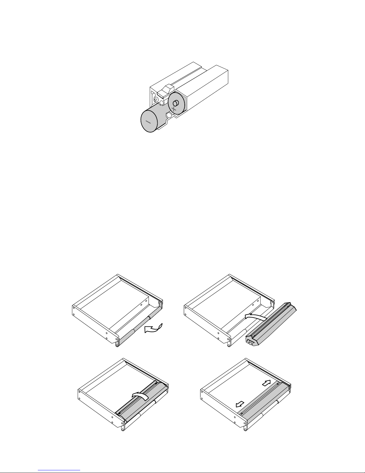
3.1.1 Removing the battery compartment
Remove the battery pack by releasing the two slide-locks, tilting the compartment diagonally towards you and
lifting it out.
IMPORTANT: Keep the slide-locks pressed towards the centre till the battery compartment is completely lifted
out of the mixer.
Mode d’emploi SONOSAX SX-ST / SX-VT Page 10 de 73
3.1.2 Opening the battery compartment
The battery compartment may now be opened by un-tightening the screw on the left side. Remove the plastic
side cover and insert 12 rechargeable Nickel-Metal-Hydride (NiMH) batteries or eventually alkaline batteries.
NOTE: On the left side of the battery compartment, you will find the hexagonal wrench (2 mm) which
enable you to completely disassemble the SX-ST without using any other tool.
WARNING: Never leave discharged batteries in your SX-ST. Make sure that your SX-ST only contains
rechargeable NiCd or NiMH batteries before charging. When using dry cells use only
professional alkaline batteries to ensure optimal running time. Also check the manufacturing
date.
3.1.3 Closing the battery compartment
Replace the plastic side cover and tighten the screw. ( Do not over tighten )
NOTE: Some rechargeable D-Cells are longer than standard dry D-Cell and slight difficulty may be found
in closing the compartment if such batteries are used. Your nearest SONOSAX agent or the
manufacturer in Switzerland can provide assistance if a problem arise due to this difference in
length.
Replace the battery compartment while holding in the slide-locks and make sure the power contacts are
correctly positioned. The battery compartment is in place when the slide-locks return easily to their original
position.

Mode d’emploi SONOSAX SX-ST / SX-VT Page 11 de 73
3.1.4 Battery Test
The switch [Lo Batt - M - T] located below the level meters lets control the charge of the batteries. When
depressed toward its momentary position, the lower level meter will indicate the average voltage per cell
between 0.9 V and 1.6 V
3.1.5 Low Battery alarm [LO BATT]
When the average voltage per cell reaches 1.05V, the [Low Batt] Led will automatically start blinking. This
alarm means that about 10 to 20 minutes of use remain available before the mixer automatically turns off. This
auto-shut down protects the accumulators from excessive discharge
3.1.6 Battery charger (option for SX-ST Series only)
An external NiCd or NiMH battery charger is available for the SX-ST Series. (part nr SX 008415 )
You do not need to remove the cells from the battery compartment to individually recharge the batteries.
A connector located at the right side of the battery compartment is provided to recharge all 12 cells at once.
Simply remove the battery compartment as described at section 2.2.1 and connect appropriate charger to the
battery pack
WARNING: - Never attempt to charge alkaline D-Cell batteries ( high risk of explosion !!)
- Charger must be suitable for 14,4 V batteries.
- Make sure that your NiCd or NiMh batteries accept high current charge when using a fast
charger
3.2 External DC supply ( SX-ST only )
The SONOSAX SX.ST can be powered from any regulated DC power supply or from an external battery bank
ranging from 11 to 18 Volts and capable of delivering at least 2.5Amp. The average power consumption is
approximately 16 to 24Watts depending of its configuration, which represents approx 2Amp under 12V.
The mixer is delivered with a universal AC/DC main adapter accepting a voltage range from 100 to 260V AC,
50Hz to 60Hz. Thus it can be used worldwide without any modification or adjustment. A spare power is
available from your dealer or SONOSAX under reference number: SX-008450.
The DC connector [DC IN] is located on the rear panel.
The mating cable connector is a XLR4-F
Pin 1 = GND or negative / Pin 4 = +11 to +18VDC or positive
Connect the external power supply to the [DC IN] located on the rear panel. Turn the switch to [POWER] to
turn on the mixer. The green LED should light. If it does not light:
¾Check that the external voltage is between 11 et 18V DC.
¾Check that your power supply can sustain at least. 40 watts
¾Check that the DC plug is correctly wired.
3.2.1 Automatic changeover of the DC power source
The internal DC/DC converter circuitry is designed to automatically changeover between the internal batteries
and the external DC power supply. Turning OFF the console to change the power source is not necessary.
While turning on the mixer, when an external DC power supply is connected and the batteries are installed,
the internal DC/DC converter will automatically switch on the external DC. If the external DC supply fails or if
the voltage drops below 10.5 VDC then the DC/DC converter will automatically switch over to the internal
batteries.
When the battery voltage drops below 1.00V per cell, the DC/DC converter will switch automatically to the
external DC power supply, providing that the external DC source was connected after powering On the
console.
NOTE: the switch over is absolutely silent, no noise, pops or clicks during will be heard

Mode d’emploi SONOSAX SX-ST / SX-VT Page 12 de 73
3.3 Main power supply ( SX-VT only )
The SONOSAX SX-VT mixing consoles are comes with their dedicated external main power supply and
should not be used with a power supply other than that supplied with the original mixer
The external power supply is designed to accept line voltages between 100 and 260V, 47-64 Hz. A voltage
switch located on the rear of the housing allows selection of different voltages 110/120VAC or 220/240VAC.
WARNING: Make sure the voltage selector matches the local voltage BEFORE connecting the main cable
to the power supply
The power supply is connected to the network by mean of a standard IEC socket that meets all international
safety standards. Make sure the cord is properly grounded. For your own safety, it is recommended not to
remove the ground connection or fail to make this connection.
Mode d’emploi SONOSAX SX-ST / SX-VT Page 13 de 73
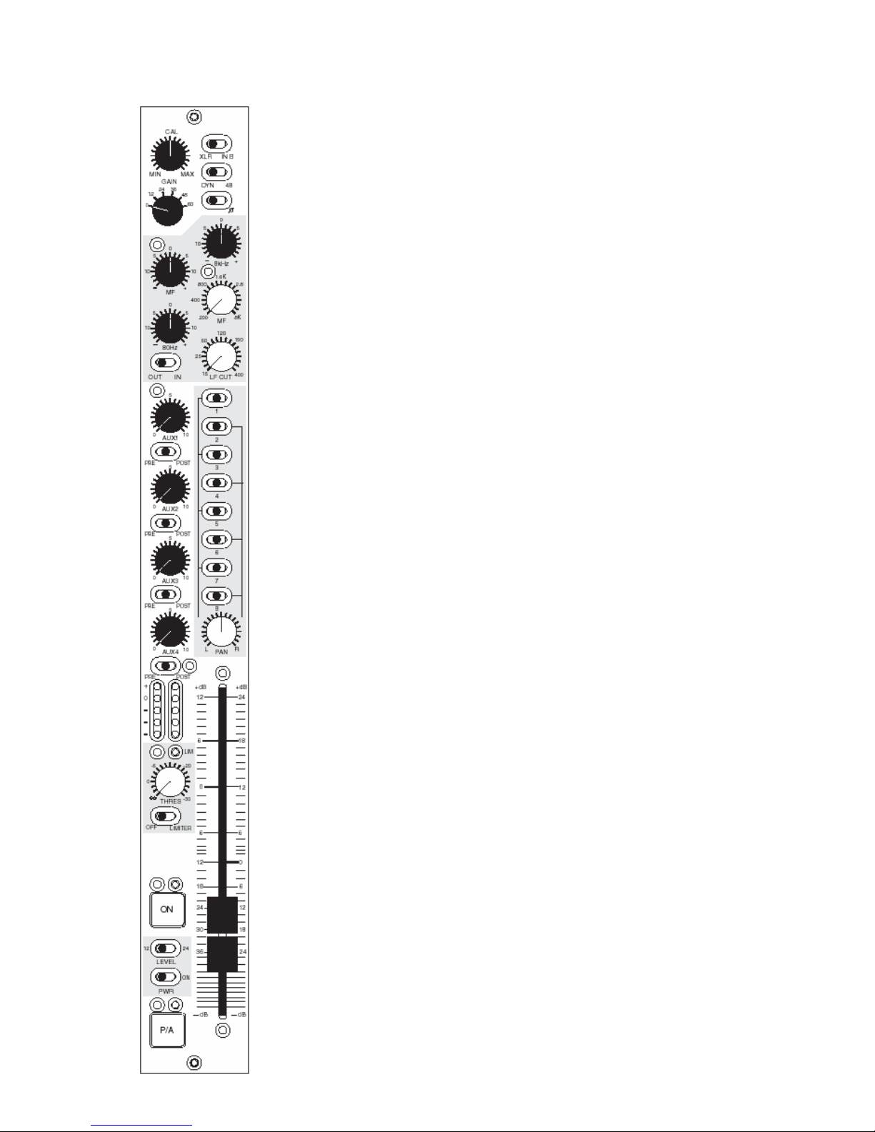
4. MIC/LINE INPUT MODULE
Les consoles de mixage professionnelles traditionnelles sont en général
basées sur la même structure d’entrée. Le signal provenant du microphone
passe par un inverseur de phase puis par un atténuateur (ou PAD) pour
atténuer le signal avant que celui-ci n’atteigne l’étage d’amplification. Certaines
consoles utilisent même un transformateur avant le premier étage afin de
simplifier le circuit. Réduire le signal avant de l’amplifier augmente le bruit de
fond. Cela limite aussi l’amplitude du signal d’entrée qui peut être autorisé
avant qu’une saturation n’intervienne. Certaines consoles ajoutent même un
coupe-bas avant le transformateur pour l’empêcher de saturer en présence de
basses fréquences de forte amplitude. Cette méthode bien que salvatrice dans
certains cas, comme par exemple dans des conditions de vent violent,
provoque de la distorsion de phase. Pendant des années cette topologie de
circuit a été utilisée pour l’enregistrement analogique et perdure encore
aujourd’hui.
Les nouveaux étages d’entrée des SONOSAX SX-ST & SX-VT n’atténuent pas le
niveau micro avant son amplification. A la place, nous contrôlons le gain de
l’amplification et de ce fait aucun bruit de fond ne vient s’ajouter à cause de
cette méthode. Utiliser des circuits sans transformateur évite d’introduire de la
rotation de phase inutile, élimine les risques de saturation du transformateur
aux basses fréquences, offre un meilleur temps d’attaque et permet d’avoir une
très large bande passante avec une réponse en fréquence la plus plate
possible, comme requis par le SACD.
Grâce à une conception soignée des étages d’entrée amplificateurs et au choix
des meilleurs composants disponibles à ce jour, il est désormais possible
d’accepter un niveau d’entrée plus important avant saturation. Les étages
d’entrée conventionnels demandent à l’opérateur d’effectuer un dosage délicat
entre le gain d’entrée et le fader de la voie afin d’éviter une éventuelle
saturation de l’étage d’entrée ou une remontée du niveau du bruit de fond.
Ainsi, avoir en même temps un bruit d’entrée très faible et une grande réserve
de dynamique est désormais une réalité.
.

Mode d’emploi SONOSAX SX-ST / SX-VT Page 14 de 73
4.1.1 Input selector [ XLR – IN B ]
The mono Mic/Line input accepts connection of any type of dynamic or condenser microphone or any external
analogue source at line level. The inputs are electronically balanced type without transformer.
Each input provides with two different type of connections: a conventional XLR-3F receptacle and the “B” input
on a multi-ways 25pin Sub-D connector [IN B 1-8]. This is useful when different sources are frequently
swapped (e.g. a set of microphones and a multi-track recorder/player) or when a set of microphones are
connected using a stage box and a multi-ways cable.
Position XLR: XLR-3F connector is selected
Pin1 = Gnd / Pin2 = High (+) / Pin3 = Low (-).
Position IN B: the 25pin Sub-D connector is selected
(please refer to the wiring diagram)
To connect an unbalanced source such as CD Player, Minidisk or else, pin 3 must be bridged to pin 1 (Gnd)
and wired to the Gnd of the source. Then use pin 2 for the unbalanced input signal.
WARNING: Never use the [48V] Phantom in case of unbalanced connection or you could severely
damage the source!
NOTE: The 25pin Sub-D connector is NOT a Line level input only, it provides with the same facilities
as on the XLR’s like phantom power and phase reverse. The wiring conforms to most popular
equipments to allow the use of “standard” ready made multi-ways cables.
4.1.2 Direct channel Output [ LINE OUT ]
Each input channel has a direct output whose source can be taken either EQ Pre or Post EQ or Post Fader.
The selection is done through an internal switch on the circuit board.
The direct channel outputs are at line level, electronically balanced transformer-less. They are available on the
connector 25-pin D-Sub [LINE OUT] on the rear panel. Please refer to the wiring diagram in the addendum for
the pin out of this connector.
4.1.3 Phantom power [ DYN - 48V ]
This switch enables or disables the 48Volts phantom power on the corresponding channel.
Position DYN: 48V phantom power is OFF – for use with dynamic microphones or line input.
Position 48: 48V phantom power is ON – for use with condenser microphones.
WARNING: - Never use the 48V Phantom in case of unbalanced.
- Never use the 48V Phantom when an external device other than a condenser microphone is
connected to the input or you may severely damage the output circuitries of that device.
- The 48V will be applied to either to the XLR or to the [INPUT B] according to the Input Select
switch. Caution must be taken when equipments other than a condenser microphone are
connected to the 25pin Sub-D.
NOTE: The latest generations of microphones operate almost exclusively with 48 V Phantom, as this
mode provides an excellent common mode rejection (CMRR), only this mode of microphone
powering is available on the SX-ST / SX-VT. Adapters to convert 48V phantom to T12 or P12
are made available by some microphone manufacturers.
4.1.4 Phase reversal [ Ø]
This switch reverses the polarity of the input signal, which corresponds to a phase rotation by 180 degrees.
It can be used to correct a reversed cable wiring or to address a phase problem between two microphones
due to their placement while recording in stereo. It can also be used to progressively decode a M/S signal on
a three ways decoding method.

Mode d’emploi SONOSAX SX-ST / SX-VT Page 15 de 73
4.1.5 Input GAIN setting [ GAIN ]
The primary input stage allows a wide range of input gain adjustment, ranging from -20dB to +80 dB. The
maximum allowable input level is +25 dBu.
The input gain is precisely controlled in two steps by mean of a rotary switch and a potentiometer; the rotary
switch sets a primary gain of 0, 12, 24, 36, 48 or 60 dB. Then, the potentiometer (also called TRIM) is used for
a progressive and fine gain adjustment within a range of -20dB to +20 dB from the centre CAL position.
An additional +12dB or +24dB of gain is available on the linear Fader (see next chapter).
NOTE: the overall gain range is quite wide and therefore the gain must be adjusted with cautions.
Check the input level using the Pre-Fader Level Meter and/or activate the PFL. An excessive
gain will leave little with headroom and can lead to clipping. On the opposite, a level set too
low will lead to a poor signal to noise ratio.
4.1.6 Limiter (non-VCA version)
Each input channels has its own independent Limiter which is part of the microphone pre-amplifier circuitries.
It is engaged by the switch [OFF – LIMITER].
The potentiometer [THRES] sets the threshold level above which the limiter becomes active. The threshold
can be adjusted between infinite and - 30dB below the nominal level. The attack time is very fast (half sine
wave only) and the release time depends of the modulation's program.
The activity of the limiter is indicated by the green Led located just above the potentiometer. It lights up as
soon as the Threshold level is reached. As long as the LED remains dark, the Limiter is inactive and has
absolutely no effect on the audio signal.
NOTE: To protect the input circuitries and to avoid clipping, the Limiter will be automatically activated
2dB before clipping even if the Limiter switched Off or set to "infinite". This feature also
provide with an additional 8dB of headroom before clipping.
4.2 Filtrer and Equalizer
The SONOSAX SX-ST / SX-VT input module is equipped with a powerful filtering and equalization section. Its
design is derived from our previous model SONOSAX SX-S on which the efficiency and sonic integrity have
been well proven in practice for decades.
4.2.1 Sweep Low Frequencies Cut [ LF CUT ]
Also called High Pass Filter, this sweep LF-Cut is commonly used to remove unwanted low frequency noises
such as room rumble, electrical hum, wind noise, popping, etc
The cut-off frequency can be adjusted from 15 Hz up to 400 Hz with a fixed slope of 18dB per octave.
This low-cut filter is located after the preamp stage. In some situations, using an external dedicated low-cut
filter such as the LC60 LC120 from Schoeps for example may help to reduce the low frequency induced by
strong winds on the micro capsules before the preamp stage.
.
NOTE: The [EQ IN/OUT] switch can be configured to include the LF Cut or not, depending on the
position of the jumper S-7 on the circuit board. By default, the LF Cut is not dependant of the
[EQ IN/OUT] switch.

Mode d’emploi SONOSAX SX-ST / SX-VT Page 16 de 73
4.2.2 3 bands semi-parametric Equalizer [ EQ ]
A 3-band semi parametric equalizer can be engaged by mean of the switch [EQ IN/OUT] located in the filter
section. It is also used for instant comparison of filtered and non-filtered audio.
•80 Hz and 8 kHz: these two filters have a shelve curve. Bass and treble adjustments are controlled by
the [80Hz ] and [8kHz] knobs within a range of ±15 dB.
•MF: is a semi-parametric (sweep frequency) equalizer with a broad fixed bandwidth. One
potentiometer progressively adjusts the central frequency from 200 Hz to 8 kHz, the
other adjusts the amplitude within a range of ±15 dB.

Mode d’emploi SONOSAX SX-ST / SX-VT Page 17 de 73
4.3 Mix busses assignments [ 1 to 8 ]
The SX-ST / SX-VT series are equipped with mix busses commonly called "Groups".
Input channels are assigned to these mix busses using the routing selectors [1 to 8]. These three positions
routing switches are used to configure either 8 individual Mono groups or up to 4 Stereo groups or a free
combinations of Mono and Stereo groups.
The routing selector [1 to 8] can be configured in two different ways to suit each user's requirement. Thus, the
input channels to mix bus assignment can be configured in two distinct ways:
Either: Pre-Fader / Off / Post-Pan (default value)
Or: Post-Fader Pre-Pan / Off / Post-Pan (the PAN is always post fader)
The assignment mode is determined by a soldering jumper on the input circuitry. (**see note)
This advanced bus assignment selector allows complex routing configurations. Each channel can be
individually assigned Pre-Fader or Pre-Pan (depending on the chosen configuration) to a Mono group used for
example for track laying, and simultaneously this channel can be mixed Post Pan to a Stereo Group as main
stereo mix.
Logically, an individual track is Mono and therefore should not be affected by the PAN Pot. Alternatively, the
PAN Pot is needed to build a stereo group.
The selector can then assign each input channel to the mixing buses 1 to 8, as follows:
Switches 1 to 8 at centre position: no audio is assigned to the corresponding mix bus
Switches 1-3-5-7 set to the left: assign the channel to odd busses Post PAN
Switches 1-3-5-7 set to the right: assign the channel to odd busses Pre-PAN (post fader)
or Pre Fader depending on the configuration
Switches 2-4-6-8 set to the right: assign the channel to even busses Post PAN
Switches 2-4-6-8 set to the left: assign the channel to even busses Pre-PAN (post fader)
or Pre Fader depending on the configuration
The two white lines drawn on either side of the selector give a clear view of the channel assignment: when the
switch is positioned towards the white line, the assignment is always Post Pan (hence post fader).
A good tip is to remember that, conventionally, odd busses correspond to the Left channel and even busses
correspond to the Right channel of a stereo group. Thus, by positioning odd switches to the left and even
switches to the right you are in any logical Post-PAN assignment to a stereo mix bus.
On the Master module, the eight mix busses are grouped per pairs: 1/2 – 3/4 - 5/6 – 7/8 thus allowing to
control the output levels of a stereo group by mean of a single Master Fader.
** NOTE: On the first series of SX-ST mixers with serial nr 0433'0070 and lower, the configuration mode
Pre Fader or Post Fader/Pre Pan is not determined by a solder bridge but requires a
modification on the circuit board. Please contact SONOSAX or your local distributor if you
want to make this change.
4.3.1 Panoramic Potentiometer [ PAN ]
The PAN Pot knob progressively balances the modulation from left to right when used in conjunction with the
Mix Busses Selector switches located above.

Mode d’emploi SONOSAX SX-ST / SX-VT Page 18 de 73
4.4 Auxiliary Sends [AUX 1 to 4]
The SX-ST / SX-VT series are equipped with four Auxiliary mix busses [AUX 1 à 4] commonly used to create
separate mixes for headphone cueing, effect sends, stage monitor mixes and all kinds of different sub-mixes
Potentiometers [AUX 1] to [AUX 4] set the level on the<mix busses from – infinite (mute) to +10dB. These four
busses are summed by the Master Aux on the Master&Monitoring module.
4.4.1 AUX busses assignment [ PRE–OFF–POST ]
These 3 positions switches assign the modulation to the Aux mix busses either before [PRE) or after [POST]
the channel fader. In centre [OFF] position, no signal is sent to the corresponding AUX mix bus.
4.4.2 Channel fader
A high quality, plastic conductive, 100mm linear fader allows precise control of the signal level sent to the
Group mix busses 1 to 8, to the Post Fader Aux sends and to the direct channel output if set to post-fader.
The fader has a logarithmic course with two different scales graduated in decibels on each side of the cursor
to match with the level switch setting (see chapter below).
The scale on the left is conventional from minus infinite to +12dB, on the right side it goes up to +24dB.
4.4.3 Level switch [12 - 24]
The [12 - 24] level switch lets you choose between two different gain ranges on the channel Fader.
In position 12, the fader has a conventional course from minus infinite up to +12dB of gain. In position 24, an
additional amplification of 12dB is applied BEFORE the fader for total gain of up to +24dB on the fader
While recording “on location” huge dynamic jumps are very common and sometime difficult to handle as the
input gain must be rapidly adjusted to avoid either overloads or weak audio levels. This forces the sound
engineer to frequently use both hands on one channel to make a delicate adjustment between the input gain
and the mix level on the fader.
The input stage in the SX-ST / SX-VT is having such significant headroom that it is usually not necessary to
reduce the input gain. However, when the ambiance sounds become more silent, it may be necessary to
increase the level so much that the traditional +12dB fader gain is not enough. Switching to the +24 position
ensure sufficient gain margin on the fader to keep hands and concentration for the mix rather than loosing
attention in controlling the input gain.
NOTES: the level switch should not be used during recording as it causes a level jump of 12dB. The
additional 12dB of gain is applied to all post fader signals.
4.4.4 Dual Peak Level Meters
The dual 5 led's Peak Meter shows both Pre and Post fader modulation levels. The peak-meter behaves
either in DOT mode or as a conventional Bargraph, depending on the switch [DOT-OFF-BAR] located on the
Master&Monitoring module. The 5 leds indicate following level:
•Red : +6dB light on 6dB above nominal level
•Yellow : 0dB nominal level
•Green : -10dB
•Green: - 20dB
•Green: - 40dB
- In case of overload while in Bargraph mode, all leds turn off except the Red led.
- In case of overload while in DOT mode, all leds light on.
NOTE: the PRE fader level is always monitored even if the channel is turned Off (Muted)

Mode d’emploi SONOSAX SX-ST / SX-VT Page 19 de 73
4.4.5 On / Mute Key [ ON ]
This key activates or mutes the channel. This function is absolutely noiseless and affects the mix busses 1 to
8, the Pre and Post fader Aux Sends, the channel solo, the direct output and eventually the Insert send/return.
The green Led located just above confirms that the channel is turned [ON].
NOTE 1: - While powering up the mixer [Power ON] all channels remaining muted by factory default.
This logic can be reversed through S8 Jumper on the input circuitry.
- By default le green led indicate that the channel is active. This logic can be reversed through
S8 Jumper on the input circuitry.
NOTE 2: - For monitoring purposes, the PFL and Pre Fader level meter remain available even if the
channel is muted.
4.4.6 PFL/AFL Pre-Listening [ P/A ]
The [P/A] key is used to individually listen to channel's modulation before the fader [PFL] or after the fader
[AFL]. Thus, the settings of the channel such as the input gain, LF Cut and Filters can be adjusted precisely,
without being affected by listening to other channels. Multiple channels can be summed in PFL/AFL mode.
When a [P/A] key is activated the channel becomes audible on the primary monitoring output in place of the
current selection, and its level is displayed on the main modulometer.
A selector located on the Master/Monitoring Module let choose between the 3 operating modes of the [P/A]
key: SOLO/AFL/PFL
The Pre-Listening function is indicated by the yellow Led located above the [P/A] key. It light On in PFL and
AFL mode or flashes while in SOLO mode
When the [P/A] key is disabled, the monitor and the modulometer return to their previous selection
NOTES: - PFL monitoring remains available even if the channel is muted.
- Jumper S12 (L) and S13(R) determine whether the AFL is taken Pre or Post PAN pot
4.4.7 Channel power on switch [PWR –ON])
It powers ON or OFF the entire input module. This function is useful to save on battery power when only a few
numbers of channels are being used. An audible pop will be introduced in the mixer's outputs if this switch is
used during normal operation.
WARNING: Powering the channel On or Off generates an audible noise.

Mode d’emploi SONOSAX SX-ST / SX-VT Page 20 de 73
4.5 VCA groups selector (modules with VCA only)
The SX-VT series can be equipped with VCA's Mic/Line Input module (Voltage Controlled Amplifier). Thus, the
channel's fader does not control the modulation level but a DC voltage that drives the VCA circuitry. This
technology offers the possibility of setting up an optional VCA grouping system to build up to eight
independent groups. A VCA group controls the mixing level of a large group of channels (such as drums,
horns, backing vocals, etc.) by mean of a single fader, thus, providing an easier global control of that particular
mix group.
The VCA Group Selector assigns the channel to one of the 8 VCA Groups. Each group is thus controlled by a
"Group Master" fader through a DC voltage.
NOTE: In position 0 or 9, the channel is disconnected from the VCA grouping system.
4.6 Compressor (modules with VCA only)
This switch engages or disengages the compressor. The compressor is used to reduce the global dynamic of
the modulation. In case of extreme amplitudes or peals of modulation, heavy distortion may occur, especially
with digital recording equipment.
To avoid this kind of distortion or, for example, to avoid loudspeakers getting damaged by overload, use the
compressor. Compressors can also be used to change the sound of an instrument by applying extreme
settings. The operating principle is based on an automatic gain control which reduces the amplitude and
thereby restricts the original dynamics on a given range.
4.6.1 Threshold
It sets the threshold level of the compressor on a range between +infinite to -30dB. Generally the threshold
level for compressors is set below the normal operating level to allow upper dynamics to be musically
compressed. For high ratio settings (near limiter function), the threshold level is set above the normal
operating level in order to provide reliable signal limiting and thus, protects subsequent equipments.
The activity of the Compressor is indicated by the green Led located just above the potentiometer. It lights up
as soon as the Threshold level is reached. As long as the LED remains dark, the Compressor is inactive and
has absolutely no effect on the audio signal
4.6.2 Ratio
It controls the compression ratio between the input and output levels of modulation exceeding the threshold
level. The range can be adjusted with the RATIO knob from a 1:1 ratio to an infinity:1 ratio.
4.7 On Air Signalling (SX-VT only)
ON AIR signalling is available on each input channel and can be enabled with Dip switch S5-B. The On Air
signalisation is turned On or Off by moving the Fader up and down, providing that the channel is turned ON.
The ON AIR Led on the Master module will light On and Off accordingly, and a ON AIR logic command is
available on the "Remote and Signalling" 25pin Sub-D connector.
When ON, a +3,3VDC voltage is available on this connector. Please take note that a maximum of 20mA can
be drawn on this command which is only foreseen to drive a low power external device such as a relay or an
opto-coupler system. Usually it is that external system that will drive the ON AIR lamps in the control room and
the studios.
4.8 Fonction MUTE
a MUTE function can be individually enabled on each Mic/Line input module (with or without VCA) with Dip
switch S5-A located underneath the channel fader.
As soon as any "Mute enabled" channel is turned ON and its channel fader is ON, the MUTE Led on the
Master module will turn ON, indicating the Mute function is activated, and the control room volume will be
attenuated by 20dB.
The Mute function can also be activated by toggling the On/Off button, providing that the fader is moved up.
This function is used by DJ's and operators that need to talk into the program material to avoid feedback
trough the control room loudspeakers.
Other manuals for SX-ST
2
This manual suits for next models
1
Table of contents
Other Sonosax Music Mixer manuals


Popular Music Mixer manuals by other brands

Grommes~Precision
Grommes~Precision Precision Electronics G228 instruction manual

Behringer
Behringer Pro Mixer VMX100 user guide

Yamaha
Yamaha Studio Manager V2 DM2000 Editor quick start guide

Omnitronic
Omnitronic TRM-402 user manual

Alesis
Alesis MultiMix6FX Reference manual

Studer
Studer D950 operating instructions


Extron electronics
Extron electronics MIX 301 user manual

Electro-Voice
Electro-Voice ELX-1A Owner's operating and service instructions

Topcon
Topcon X35 Operator's manual

Radio Shack
Radio Shack 32-2057 user guide

thomann
thomann the t.mix 403-USB Play user manual

Euphonix
Euphonix System 5 installation guide