Sonosax SX42 User manual

PROFESSIONAL PORTABLE
MIXING CONSOLE
SONOSAX
SX42
User's Manual
Audio Equipment Manufacturer
SONOSAX SAS S.A.
Ch. de la Naz 38
1052 Le Mont s/Lausanne
SWITZERLAND
Tel: +41 21 651 0101
Fax: +41 21 651 0109
Web: www.sonosax.ch
Version 1.2
Printed in Switzerland, April 2003

SX42 User's Manual Page 2 of 26
TABLE OF CONTENTS
1. INTRODUCTION ................................................................................5
2. GENERAL DESCRIPTION.................................................................5
2.1 Key Features .......................................................................................................5
2.2 Options................................................................................................................6
2.2.1 Two channels equalizer ................................................................................................... 6
2.2.2 A/D converter ...................................................................................................................6
2.2.3 HF transmitter/receiver..................................................................................................... 6
2.2.4 External power supply...................................................................................................... 6
2.2.5 Accumulators....................................................................................................................6
2.2.6 Batteries charger.............................................................................................................. 6
2.2.7 Nylon case ....................................................................................................................... 6
3. OPERATING INSTRUCTIONS...........................................................7
3.1 Safety Instructions .............................................................................................7
3.2 Battery Power Mode ...........................................................................................7
3.2.1 Opening the battery compartment.................................................................................... 7
3.2.2 Closing the battery compartment ..................................................................................... 8
3.2.3 Batteries charger (optional).............................................................................................. 8
3.2.4 Battery test ....................................................................................................................... 8
3.2.5 Low battery alarm............................................................................................................. 8
3.3 External DC Power Mode ...................................................................................8
3.3.1 Fuse replacement............................................................................................................. 8
3.4 Switching On The Mixer.....................................................................................9
4. DETAILED DESCRIPTION...............................................................10
4.1 Left Panel ..........................................................................................................10
4.1.1 Inputs (IN1 to IN4).......................................................................................................... 10
4.1.2 Bus input (BUS IN) ......................................................................................................... 10
4.1.3 External DC input (DC IN) .............................................................................................. 10
4.2 Right Panel........................................................................................................11
4.2.1 Main outputs (OUT L & OUT R) ..................................................................................... 11
4.2.2 Stereo sub output (SUB OUT)........................................................................................ 11
4.2.3 Headphones output (PHONES) ..................................................................................... 12
4.2.4 Direct outputs (OUT 1to4) .............................................................................................. 12
4.2.5 External input (RET IN) .................................................................................................. 12

SX42 User's Manual Page 3 of 26
4.2.6 User panel......................................................................................................................12
4.2.7 Batteries compartment ................................................................................................... 12
4.3 Top Panel ..........................................................................................................13
INPUTS SECTION (IN1 to IN4)...................................................................................... 13
4.3.1 Phantom power (DYN 48V)............................................................................................ 13
4.3.2 Input attenuator (MIC PAD)............................................................................................ 13
4.3.3 Gain (LO 2 3 HI) ............................................................................................................. 14
4.3.4 LF filter (80 LIN 120) ...................................................................................................... 14
4.3.5 Pan (MS L C R) .............................................................................................................. 14
4.3.6 Input level link (LINK 1 to 2 and LINK 3 to 4) ................................................................. 14
4.3.7 Phase reversal (0 180)................................................................................................... 15
OUTPUTS SECTION (L&R)........................................................................................... 15
4.3.8 Talkback and oscillator (MIC OFF OSC)........................................................................ 15
4.3.9 Output attenuator (LINE ATT) ........................................................................................ 15
4.3.10 Limiter (LINK OFF ON) ............................................................................................... 15
4.3.11 Master levels link (LINK R to L) .................................................................................. 16
ACCESSORIES SECTION ............................................................................................ 16
4.3.12 Accessories power (OFF ON)..................................................................................... 16
4.3.13 ACC 1 switch (OFF ON) ............................................................................................. 16
4.3.14 ACC 2 switch (OFF ON) ............................................................................................. 16
4.4 Front Panel........................................................................................................16
4.4.1 Input rotary faders (IN1 to IN4)....................................................................................... 16
4.4.2 Input signal peak indicator (OVD LED) .......................................................................... 17
MONITORING SECTION ............................................................................................... 17
4.4.3 Monitor source (1 2 3 4 L R M ST MS)........................................................................... 17
4.4.4 Phones level (1 2 3 4 5) ................................................................................................. 17
4.4.5 Meters source (MON OUT) ............................................................................................ 17
4.4.6 Monitor select (RET DIR) ............................................................................................... 18
4.4.7 Level meters................................................................................................................... 18
4.4.8 Meters backlight ............................................................................................................. 18
4.4.9 Power LED ..................................................................................................................... 18
4.4.10 Talkback microphone ................................................................................................. 18
MASTERS SECTION ..................................................................................................... 18
4.4.11 Power (OFF ON)......................................................................................................... 18
4.4.12 Output signal peak indicators (OVD LED) .................................................................. 18
4.4.13 Output rotary faders (L & R) ....................................................................................... 19
4.4.14 Talkback push buttons (L & R) ................................................................................... 19
4.4.15 Battery test (BATT)..................................................................................................... 19

SX42 User's Manual Page 4 of 26
4.5 Bottom Panel ....................................................................................................19
4.5.1 Equalizer (optional) ........................................................................................................ 20
4.6 Internal Settings ...............................................................................................20
4.6.1 Headphones level adjustment........................................................................................ 20
4.6.2 Inputs monitoring signal ................................................................................................. 21
4.6.3 Sensitivity of the return input.......................................................................................... 21
4.6.4 Output limiters level adjustment ..................................................................................... 21
4.6.5 Subsidiary output level adjustment ................................................................................ 21
4.6.6 Direct outputs level adjustment ...................................................................................... 21
4.6.7 Sensitivity of the bus input ............................................................................................. 21
4.6.8 Level meters mode......................................................................................................... 21
5. APPENDIX........................................................................................22
5.1 Specifications ...................................................................................................22
5.1.1 Summary of characteristics............................................................................................ 22
5.1.2 Mic/Line inputs ............................................................................................................... 22
5.1.3 Main outputs................................................................................................................... 23
5.1.4 Equalizer (optional) ........................................................................................................ 23
5.1.5 Power supply.................................................................................................................. 23
5.1.6 Dimensions and weight .................................................................................................. 23
5.2 Block Diagram ..................................................................................................24
5.3 Main Board Adjustments .................................................................................25
5.4 Front Board Adjustments ................................................................................25
5.5 Tips On Using Your Mixer................................................................................26

SX42 User's Manual Page 5 of 26
1. INTRODUCTION
Congratulations on your purchase of your SONOSAX SX42 professional portable mixing
console, which has been manufactured to deliver many years of excellent performance. The
reliability of the SONOSAX SX42 is due to a high-tech design, combining the highest
components density as possible, with a meticulous hand assembly.
As with all SONOSAX products, the SX42 portable mixer is built without any compromise in
quality, using only the best components available and a severe quality control. The result of this
research and development project is an ergonomic mixing console with extraordinary
characteristics.
The information and instructions contained in this manual are necessary to ensure safe
operations of your equipment and to maintain it in good working condition; please read it
carefully.
2. GENERAL DESCRIPTION
The SONOSAX SX42 is an ENG/EFP mixer of the last generation, designed in 2002, using the
latest available technologies, with the unequaled SONOSAX design and ergonomics.
Our 25 years of experience have helped us to develop and build this mixer which is designed to
obtain a minimum of 10 years life-span, despite an intensive use under the worst possible
conditions. It can be used in the rain and it's resistant to water splashes and compliant to the
IP45 standard.
Built in a strong, rugged and anodized aluminum case, the SONOSAX SX42 mixer provides the
best solution whenever top performance, versatility and small size are important. All
potentiometers are especially made for SONOSAX and watertight according to IP45. All
switches are achieved with an original and very innovative SONOSAX design. There are
magnets outside the box, controlling Reed contacts inside the box. All the Reed-type switches
are watertight (IP45) and airtight. All capacitors are of professional type, with low loss and a
long life-span.
2.1 Key Features
♦Ultra-low noise 4 inputs, 2 outputs, portable ENG/EFP mixer
♦Low consumption, battery or 12V DC powered mixer
♦Electronically balanced, transformerless inputs and outputs
♦High quality rotary fader on each input/output channel
♦Watertight IP45 Reed contact switches and faders
♦Discrete mic preamps with +48V phantom power on all input channels
♦A MS decoder is available on inputs 1-2 and 3-4
♦Signal/Overload LED indicator on each channels
♦Large scale level-meter indicators with tempered glasses
♦A link function allows you to control audio levels with only one fader for
two channels and also for both output channels
♦Two separate limiters are present and linkable on both output channels

SX42 User's Manual Page 6 of 26
2.2 Options
The SX42 mixer as been designed with the possibility of host some useful internal accessories
in mind.
For all internal accessories, a separate power supply is also included. Please contact your
nearest SONOSAX dealer or the factory for any inquiry.
2.2.1 Two channels equalizer
A three-band equalizer is available as an option, only for input channel 1 and 2.
2.2.2 A/D converter
A high quality analog-to-digital converter, 24-bit resolution and 48/96 kHz sampling frequency is
currently under development and will be available soon as an option for the SX42.
2.2.3 HF transmitter/receiver
There is the possibility to internally include one transmitter and/or one HF receiver (depending
on its size) as an accessory. In this case, the audio connections are to be done inside the mixer.
The receiver connector(s) are designed to be placed on the "user panel" located on the right
side of the unit.
2.2.4 External power supply
An universal 100-240V∼auto-ranging, 12V DC OUT power supply unit is available and
recommended for optimum performances with accessories. Its SONOSAX part number is: SX
008420.
2.2.5 Accumulators
A set of four 1.2V, 7Ah Nickel-Metal-Hydride (NiMH) accumulators is available as SONOSAX
part number: SX 002108/4.
2.2.6 Batteries charger
A universal batteries charger for NiCd or NiMH accumulators is available as SONOSAX part
number: SX 008415.
2.2.7 Nylon case
A black nylon bag is available for an easy and protected transportation of your SX42 mixer. Its
SONOSAX part number is: SX 005110.

SX42 User's Manual Page 7 of 26
3. OPERATING INSTRUCTIONS
3.1 Safety Instructions
•Read all the safety and operation instructions before operating the SX42 mixer and its
external power supply.
•Keep the instructions for further reference.
•Follow all warnings, notes and instructions in this operation manual.
•Keep the SX42 mixer and its external power supply away from heat sources such as
radiators or other devices that produce heat.
•Connect the SX42 mixer only to the optional external power supply delivered by
SONOSAX. Route power supply cords so that they are not likely to be walked on or
pinched by items placed on or against them, paying particular attention to cords at plugs,
inlets and the point where they exit the console. Keep power cords away from audio
cords.
•Do not drop objects or spill liquids onto the SX42 mixer and its power supply.
•The SX42 mixer and its external power supply should be serviced only by qualified
service personnel as your nearest SONOSAX authorized reseller.
•Do not defeat the grounding or polarization of the SX42 mixer or its power supply.
•Line voltage selectors should only be reseted and equipped with a proper plug for
alternate voltage by a qualified service technician.
•To reduce the risk of fire or electric shock, do not expose this appliance to rain or
moisture.
•Internal settings must be executed by an authorized SONOSAX distributor or reseller.
Damage due to manipulations inside the unit cancels the SONOSAX warranty
immediately.
3.2 Battery Power Mode
The SONOSAX SX42 mixer can be battery powered with four alkaline D-cells (LR20) or four
LR20 rechargeable Nickel-Cadmium (NiCd) or Nickel-Metal-Hydride (NiMH) accumulators. To
carry on less battery weight, four AA (LR6) batteries can also be used with special size
adaptors.
NOTE: The autonomy of the mixer can drastically change depending on batteries type
(alkaline, NiCd or NiMH) and quality, microphones type and LEDs light intensity.
3.2.1 Opening the battery compartment
The battery compartment is located on the right panel and it can be opened by un-tightening the
screw using a flat screwdriver. Remove the anodized aluminum cover and insert four D-cells
batteries or accumulators with their negative side first.
WARNING: Never leave discharged batteries in your SX42. To ensure optimal autonomy, use
only professional alkaline D-cells. Also check the manufacture date of the D-cells
for best performances.

SX42 User's Manual Page 8 of 26
3.2.2 Closing the battery compartment
Replace the anodized aluminum cover and tight the screw using a flat screwdriver.
NOTE: Certain D-Cells are longer than standard D-Cell batteries and slight difficulty may be
found in closing the compartment if such batteries are used. Your nearest SONOSAX
dealer or the manufacturer in Switzerland can provide assistance if a problem arise
due to this difference in length.
NOTE: A special screw with wings is also available if you don’t want to use each time a
screwdriver to open and close the battery compartment. Ask your nearest SONOSAX
dealer or the factory.
3.2.3 Batteries charger (optional)
An external NiCd or NiMH batteries charger is available as an option for the SX42. It can charge
simultaneously up to four 1.5V D-cells (LR20) or up to six AA (LR6) accumulators.
NOTE: It will take approx. 6 hours to fully recharge four NiCd or NiMH D-cell accumulators.
WARNING: Never attempt to charge alkaline D-Cell batteries!
3.2.4 Battery test
When the BATT push-button is depressed, the needle of the right level meter will indicate the
average charge per battery cell (minimum: 1V, maximum: 1.6V). In case of use with the external
power supply, the meter will indicate the voltage divided by four. For instance: a 1.5V indication
means that the external voltage is equal to 6V DC.
3.2.5 Low battery alarm
When the average charge per cell reaches 1.05V, the LED between the meters becomes red.
This alarm means that about 10 to 20 minutes are remaining before the mixer automatically
turns off. This auto-stop at 1V per cell will protect the accumulators from an excessive
discharge.
3.3 External DC Power Mode
The SONOSAX SX42 mixer can be powered from a 6V to 12V DC power supply capable of
delivering at least a current of 1A peak. The average power consumption is approximately 2 to 3
Watts, depending on microphones type and LEDs light intensity.
3.3.1 Fuse replacement
Some safety fuses protects the units from serious defects. As we are using multi-fuses instead
of traditional fuses, there’s no need to physically replacing it. The fuses will reset automatically;
if this is not the case, contact your nearest SONOSAX dealer or the factory.

SX42 User's Manual Page 9 of 26
3.4 Switching On The Mixer
•Using D-cells, NiCd or NiMH batteries
Insert four D-cell batteries with their negative side first in the battery compartment located on
the right side of the mixer. Then set the POWER switch located on the front right corner, on
the ON position to turn on the unit. The LED between the two level meters must come green,
if not:
¾Check that batteries have been inserted correctly inside the battery compartment,
with their negative side first!
•Using the external DC power supply
Connect the external power supply DC plug to the DC IN connector located on the left side of
the mixer. Then set the POWER switch located on the front right corner of the mixer on the
ON position to turn on the unit. The LED between the two level meters must come green, if
not:
¾Check that the DC output voltage selector located on the external power supply is on
the 12V position.
SX42 User's Manual Page 10 of 26
4. DETAILED DESCRIPTION
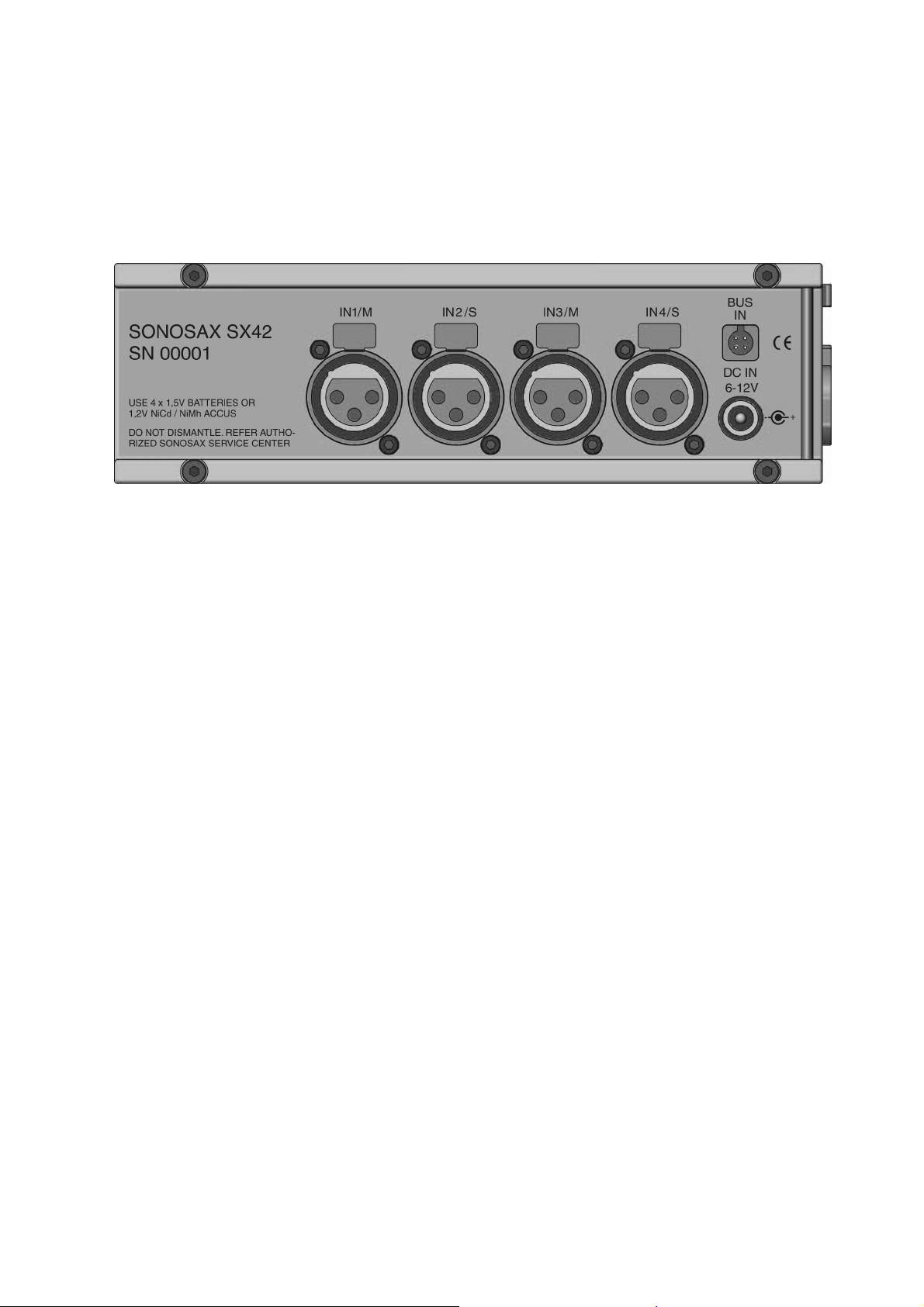
4.1 Left Panel
The left panel includes four Mic/Line balanced inputs, an external DC input and a bus input as
shown hereunder:
4.1.1 Inputs (IN1 to IN4)
Each mono input channel is electronically floating balanced, transformerless and optionally
equipped with RF filters.
The input connectors are XLR type connectors where: PIN 1=GND, PIN2=HI (or +) and
PIN3=LO (or -).
To connect the mixer to an unbalanced source like consumer CD or MD player, make a bridge
between PIN1 and PIN3, and connect this to the GND of the source. Then, use PIN2 as the
unbalanced signal input.
NOTE: Never use the Phantom power (48V) in this case! You can destroy the source!
4.1.2 Bus input (BUS IN)
This input allows you to connect any other external device WITHOUT ANY CONTROL over the
two mix busses of the mixer. For example you can use this stereo input to connect two
SONOSAX SX42 mixers together to obtain an 8 channels mixer.
This stereo input is unbalanced and its sensitivity is factory adjusted at +6dBu for 0dB. The
sensitivity can be internally adjusted by your nearest SONOSAX dealer or at the factory.
The BUS IN connector is a 4 poles BINDER, where: PIN1=GND, PIN2=Left, PIN3=Right and
PIN4=NC.
The corresponding cable connector is BINDER part number: REF 09-9767-70-04 or SONOSAX
part number: SX 860273.
4.1.3 External DC input (DC IN)
You can provide power to your SX42 mixer from an external power supply. The voltage must be
stabilized in a range between 6V to 12V DC. The average current consumption is around
SX42 User's Manual Page 11 of 26
500mA, but due to the internal DC/DC converter of the SX42 mixer, the peak current when the
unit is turned ON reaches 1A.
For the best performance we recommend to use the optional external power supply provided by
your nearest SONOSAX dealer or by the factory. Its SONOSAX part number is: SX 008420.
The DC IN connector is a coax-socket type connector and it can be reordered by your nearest
SONOSAX dealer or at the factory. Its SONSAX part number is: SX 860712.
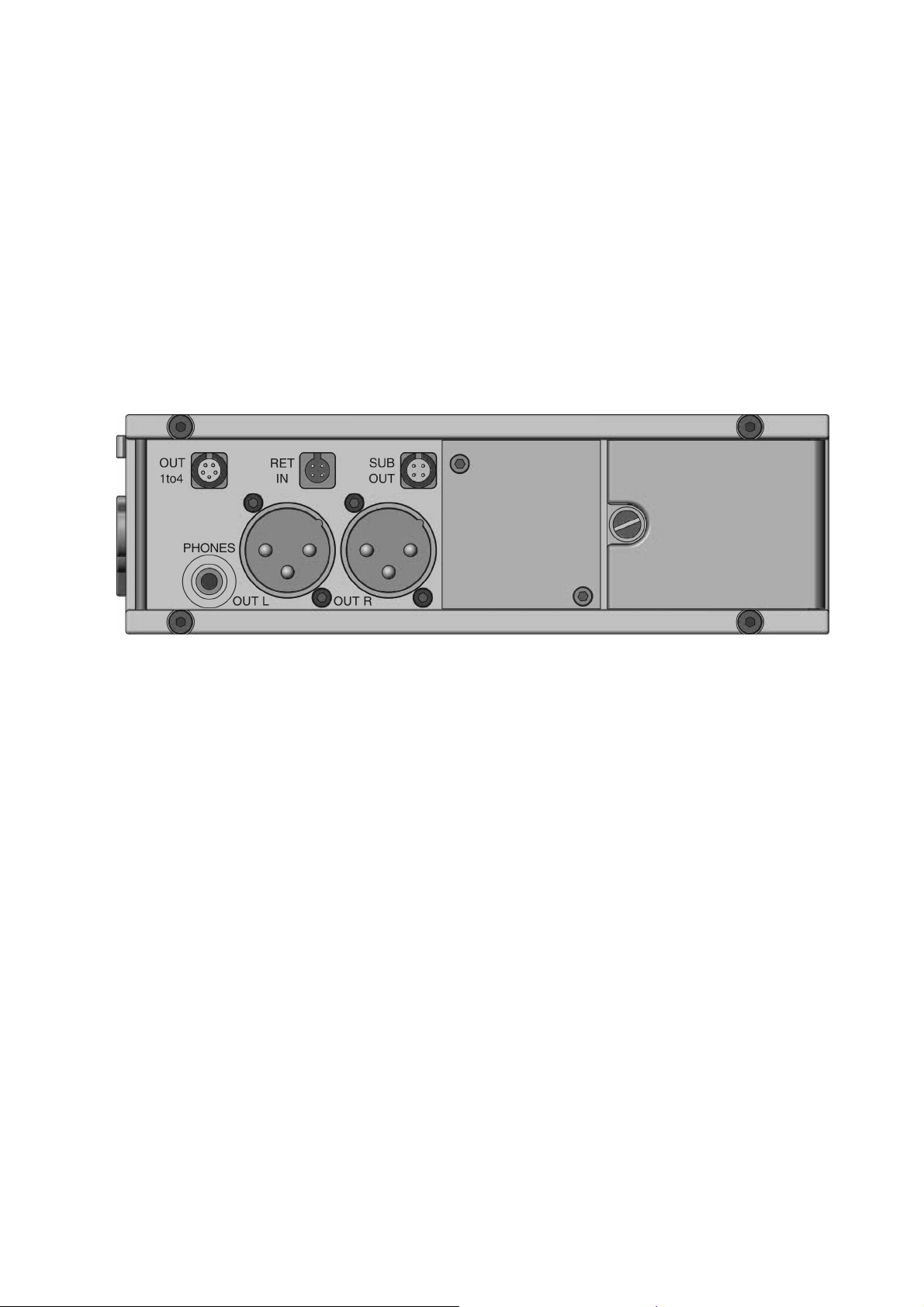
4.2 Right Panel
The right panel includes: two balanced main outputs (OUT L and OUT R), a headphones output
(PHONES), a direct line1 to line4 output (OUT 1to4), an external return input (RET IN) and
another stereo output (SUB OUT). The user panel and the batteries compartment are also
located here as show hereunder:
4.2.1 Main outputs (OUT L & OUT R)
The two main output channels (L & R) are electronically floating balanced.
The output connectors are XLR type connectors where: PIN 1=GND, PIN2=HI (or +) and
PIN3=LO (or -).
The nominal level is +6dBu or -40dBu (see Output attenuator) and the output impedance is less
than 50 ohms. It can be internally adjusted by your nearest SONOSAX dealer or at the factory.
To connect to an unbalanced input like a consumer CD or MD player, make a bridge between
PIN1 and PIN3 and connect this to the GND of the other device. Then, use PIN2 as the
unbalanced signal output.
NOTE: Even if the SX42 mixer as an internal protection, avoid sending Phantom power (+48V)
into outputs.
4.2.2 Stereo sub output (SUB OUT)
This connector provides you a subsidiary unbalanced stereo output channel. The nominal
output level is +6dBu and can be internally adjusted by your nearest SONOSAX dealer or at the
factory. You can use this output to connect for example a consumer DAT or MD recorder.
NOTE: This output can also be internally adjusted to provide one or two mono channels.
Remark: In a mono channel the audio signal is the sum of Left and Right channels.

SX42 User's Manual Page 12 of 26
The SUB OUT connector is a 4 poles BINDER, where: PIN1=GND, PIN2=Left, PIN3=Right and
PIN4=NC.
The corresponding cable connector is BINDER part number: REF 09-9764-70-04 or SONOSAX
part number: SX 860274.
4.2.3 Headphones output (PHONES)
This output allows you to connect any kind of headphones with impedance from 35ohms up to
400ohms. The nominal level is 0dBu in position 3, and it can be internally adjusted by your
nearest SONOSAX dealer or at the factory. Positions 1 to 5 have 6dB/step. See the PHONES
switch on the Front Panel and Headphones level adjustment in the INTERNALS SETTINGS
section.
NOTE: The headphone amplifier of the SX42 mixer is very loud, and in some cases this can
damage you hears!
4.2.4 Direct outputs (OUT 1to4)
This is a four channels unbalanced output, corresponding to the four input channels of the SX42
mixer. The nominal output level is 6dBu and it can be internally adjusted by your nearest
SONOSAX dealer or at the factory. Default setting is PRE, and it can be POST on request.
The OUT 1to4 connector is a 5 poles BINDER where: PIN1=GND, PIN2=IN1, PIN3=IN2,
PIN4=IN3, and PIN5=IN4.
The corresponding cable connector is BINDER part number: REF 09-9790-71-05 or SONOSAX
part number: SX 860276.
4.2.5 External input (RET IN)
This is an unbalanced stereo input, mainly used for tape monitoring purpose. The nominal input
level is 6dBu and it can be internally adjusted by your nearest SONOSAX dealer or at the
factory.
The RET IN connector is a 4 poles BINDER where: PIN1=GND, PIN2=Left, PIN3=Right and
PIN4=NC.
The corresponding cable connector is BINDER part number: REF 09-9767-70-04 or SONOSAX
part number: SX 860273.
4.2.6 User panel
After two decades of manufacturing audio mixers, we find out that all customers have some
different manner to connect the mixer to the rest of their equipments. The user panel is here for
this. You can add any type of connector you need on this place. To do this, you must be a
qualified technician, or refer to an official SONOSAX service center or at the factory.
Look at the bloc diagram to find what you need, unscrew the user panel with a 2mm hexagonal
wrench and modify the panel for your connector. If you made any mistake, the user panel can
be reordered as SONOSAX part number: SX 951630.
4.2.7 Batteries compartment
In this compartment you can place four D-Cells or four AA-Cells with size adaptors. Open the
door with a flat screwdriver and introduce the batteries with their negative side first.

SX42 User's Manual Page 13 of 26
4.3 Top Panel
The top panel includes all the settings usually fixed before the shooting. These settings are
especially designed to avoid a bad movement during the shooting.
INPUTS SECTION (IN1 to IN4)
This section describes all settings available for each input channel IN1 to IN4.
4.3.1 Phantom power (DYN 48V)
This switch allows you to turn ON or OFF the phantom power of the corresponding input
channel (IN1 to IN4):
DYN position: 48V phantom power is OFF – to use with dynamic microphones or line.
48V position: 48V phantom power is ON – to use with condenser microphones.
NOTE: For more than 10 years all professional microphones can work with 48V. Due to a
much better common mode rejection ratio (CMRR), we have decided to include only
this kind of microphone power.
WARNING: Never use the 48V phantom power if you have connected any unbalanced or line
level device. This setting can destroy the connected device!
4.3.2 Input attenuator (MIC PAD)
This switch allows you to turn ON or OFF the 30dB input attenuator of the corresponding input
channel (IN1 to IN4):
MIC position: the input attenuator is OFF.
PAD position: the input attenuator is ON.

SX42 User's Manual Page 14 of 26
NOTE: The PAD position should be used with high input levels, like the ones obtained when
using high sensitivity microphones. But for a better signal to noise ratio it is better to
use the mixer without PAD if possible.
4.3.3 Gain (LO 2 3 HI)
This four positions switch allows you to adjust the gain level of the corresponding input channel
(IN1 to IN4) according to the following:
LO position: an input gain of 16dB is activated.
2 position: an input gain of 36dB is activated.
3 position: an input gain of 56dB is activated.
HI position: an input gain of 76dB is activated.
NOTE: Gain control should be used with care since the adjustment range is extensive. A
signal level set too high can cause distortion and will leave you with less headroom; a
level set too low can cause a bad signal-to-noise ratio.
4.3.4 LF filter (80 LIN 120)
This switch allows you to turn ON or OFF the low frequencies filter of the corresponding input
channel (IN1 to IN4) according to the following:
80 position: the low cut frequency is 80 Hz, the slope is 12dB/octave.
LIN position: the low cut filter is turned OFF.
120 position: the low cut frequency is 120 Hz, the slope is 12dB/octave.
NOTE: You can use this filter to remove unwanted low frequency noises such as room rumble,
wind noise, popping, etc.
4.3.5 Pan (MS L C R)
This switch allows you to route the audio signal of the corresponding input channel (IN1 to IN4)
to the main outputs, according to the following:
MS position: a MS decoded signal is routed on both Left and Right output channels.
L position: the signal is routed on the Left output channel only.
C position: the signal is routed on both, Left and Right output channels.
R position: the signal is route on the Right output channel only.
NOTE: The MS position is only available on channels 2 and 4, to activate MS on inputs 1-2,
and/or inputs 3-4.
In the MS-mode the M channel is routed to both Left and Right output channels in phase and
the S channel is routed in phase to the Left output channel and out of phase to the Right output
channel.
WARNING: When the MS position is selected on input channel 2 and/or 4, the pan setting for
input channel 1 and/or 3 will have no effects and thus becomes useless.
4.3.6 Input level link (LINK 1 to 2 and LINK 3 to 4)
This switch allows you to link level controls (rotary faders) of input channels 1 and 2 (and
respectively input channels 3 and 4) to the single level control of input channel 2 (respectively

SX42 User's Manual Page 15 of 26
input channel 4). Thus, you only need to adjust one level control, for example on input channel
4, to set the audio level of input channels 3 AND 4.
NOTE: The input level link switch is only available on input channels 1 and 3.
4.3.7 Phase reversal (0 180)
This switch allows you to reverse the signal phase of channels 2 and/or 4. This setting is useful
if you have a phase problem between two microphones or if you use MS microphones.
0° position: the signal is on phase.
180° position: the signal phase is inverted by 180°.
NOTE: The phase reversal switch is only available on input channels 2 and 4.
WARNING: If the MS position is selected on the pan switch and you decide to invert the
signal phase (of the same input channel), then the whole MS image will be
inverted on the output channels.
OUTPUTS SECTION (L&R)
This section describes all settings available for the two output channels.
4.3.8 Talkback and oscillator (MIC OFF OSC)
This three positions switch allows you to select one of the two possible sources that will be sent
on the corresponding output channel (Left and/or Right):
MIC position: sends the talkback microphone signal to the output channel.
OFF: position: the talkback microphone and the oscillator are turned off.
OSC position: the internal oscillator generates a 1 kHz sine wave tone
which is sent to the output channel (this function is usually
used during a calibration or a test process).
NOTE: The nominal output level is +6dBu (level meters @ 0dB) when the master pot is on the
0dB position.
4.3.9 Output attenuator (LINE ATT)
This switch allows you to turn ON or OFF the 46dB line attenuator of the corresponding output
channel (Left and/or Right) according to the following:
LINE position: the attenuator is turned OFF – nominal output level is +6dBu.
ATT position: the attenuator is turned ON – nominal output level is -40dBu.
4.3.10 Limiter (LINK OFF ON)
This three positions switch allows you to turn ON or OFF the two independents internal output
limiters according to the following:
LINK position: Left and Right output limiters are linked (stereo mode) and ON.
OFF position: Left and Right output limiters are turned OFF.
ON position: Left and Right output limiters are turned ON.

SX42 User's Manual Page 16 of 26
NOTE: The use of these high quality limiters helps you to avoid the overload of the output or
your recorder input. Where stereo balanced limiting is needed use the LINK position.
4.3.11 Master levels link (LINK R to L)
This switch allows you to link the Right output channel level control (rotary fader) to the Left
output channel level control. Thus, you only need to adjust the level control of the Left output
channel to set the audio level of both output channels (L & R).
ACCESSORIES SECTION
This section describes all settings available for the optional internal modules.
4.3.12 Accessories power (OFF ON)
This switch allows you to turn ON or OFF the power of any internal accessory located inside the
mixer, for example a HF transmitter.
NOTE: If the mixer is turned OFF, the accessory power is also turned OFF even if the ACC
POWER is ON.
WARNING: The internal power supply will provide to the accessories a maximum current of
200mA under 9V DC and/or a maximum current of 200mA under 5V DC.
4.3.13 ACC 1 switch (OFF ON)
This two position switch has no particular function. It has been intentionally left free for a later
use with an internal accessory. Feel free to connect it according to your needs.
4.3.14 ACC 2 switch (OFF ON)
This two position switch has no particular function. It has been intentionally left free for a later
use with an internal accessory. Feel free to connect it according to your needs.
4.4 Front Panel
The front side of the SX42 includes all the figures used during the shooting, and all the
monitoring functions.
4.4.1 Input rotary faders (IN1 to IN4)
These four rotary potentiometers (faders) allow you to progressively adjust the desired audio
level of the corresponding input channel (IN1 to IN4), within a wide level range going from -∞to
+10dBu.

SX42 User's Manual Page 17 of 26
4.4.2 Input signal peak indicator (OVD LED)
This small level indicator uses a two colors LED that will light:
GREEN: when an audio signal is present at approx.-50dB.
RED: when an audio signal is close to overload (6dB before clipping).
NOTE: There are tree levels of LED’s light intensity depending of the detected daylight. If more
daylight is detected LED’s light intensity will be increased.
MONITORING SECTION
In this area you find all the necessary switches and buttons for the headphone’s monitoring.
4.4.3 Monitor source (1 2 3 4 L R M ST MS)
This ten positions linear switch allows you to select the source you want to monitor according to
the following:
1 position: the input channel 1 is selected.
2 position: the input channel 2 is selected.
3 position: the input channel 3 is selected.
4 position: the input channel 4 is selected.
L position: the Left output channel is selected.
R position: the Right output channel is selected.
M position: a mono output (sum of Left and Right channels) is selected.
ST position: a stereo output (Left and Right channels) is selected.
MS position: a MS-decoded signal is sent to the monitor output.
NOTE: In MS position, be sure to also check the setting of the Monitor Select switch to avoid
any confusion on the source.
4.4.4 Phones level (1 2 3 4 5)
This five positions switch allows you the set the headphones level according to the following:
1 position: headphones level is -12dBu.
2 position: headphones level is -6dBu.
3 position: headphones level is 0dBu (nominal level).
4 position: headphones level is +6dBu.
5 position: headphones level is +12dBu.
NOTE: The nominal headphones output level is fixed at 0dBu and it can be internally adjusted
by your nearest SONOSAX dealer or at the factory.
4.4.5 Meters source (MON OUT)
This switch allows you to select which audio signal will drive the two level meter indicators
according to the following:
MON position: level meters will follow the monitor source signal.
OUT position: level meters will follow the output channels signal.

SX42 User's Manual Page 18 of 26
4.4.6 Monitor select (RET DIR)
This switch allows you to route the direct (L & R) or the return (RET IN) audio signal to
headphones output, according to the following:
RET position: the signal from the RET IN input is routed to the phones output.
DIR position: the signal from Left and Right output channels is routed to the
phones output.
4.4.7 Level meters
Two moving coil level meter indicators are presents to visualize the current level of the audio
signal (in VU or Peak mode, see NOTE). They have a large scale ranging from -32dB to +12dB,
are compensated in temperature and closed on the front side by tempered glasses. The right
level meter indicator also show the battery voltage, when the BATT push button is depressed.
NOTE: The factory setting is Peak for both level meters and it can be internally adjusted by
your nearest SONOSAX dealer or at the factory.
4.4.8 Meters backlight
The two level meter indicators have a red backlight with an automatic power ON or OFF
function. As soon as the detected daylight goes under a certain level, the meters backlight will
light ON. Thus, when using the SX42 mixer in a normal daylight environment the backlight is
turned OFF.
4.4.9 Power LED
This small power level indicator uses a two colors LED that will light:
GREEN: when the SX42 mixer is turned ON and it is ready to operate.
RED: when the SX42 mixer is turned ON and the batteries are low.
4.4.10 Talkback microphone
A small electret microphone with an automatic level control is located between the two level
meters and it is used for the talkback function. To use it: first select the MIC position on the
Talkback and Oscillator switch (4.3.8) located on the Top Panel and then depress the left or
right talkback push button to send the microphone signal to the corresponding output channel.
MASTERS SECTION
In this section you will find the output level controls and indicators, the talkback function and the
battery test control.
4.4.11 Power (OFF ON)
This switch allows you to turn ON or OFF the SX42 mixer.
OFF position: the SX42 is turned OFF.
ON position: the SX42 is turned ON.
4.4.12 Output signal peak indicators (OVD LED)
This small level indicator uses a two colors LED that will light:
SX42 User's Manual Page 19 of 26
GREEN: when the Limiter is active.
RED: when an audio signal is close to overload (6dB before clipping).
NOTE: There are three levels of LED’s light intensity that will depend on the amount of
detected daylight. Thus, if more daylight is detected LED’s light intensity will be
increased.
4.4.13 Output rotary faders (L & R)
These two rotary potentiometers (faders) allow you to progressively adjust the desired audio
level of the corresponding output channel (L & R), within a wide level range going from -∞to
+10dBu.
4.4.14 Talkback push buttons (L & R)
When these push buttons are depressed the signal of the selected internal source (the talkback
microphone or the oscillator) is fed to the corresponding output channel.
4.4.15 Battery test (BATT)
When this push-button is depressed, the needle of the right level meter will indicate the average
voltage per battery cell (minimum: 1V, maximum: 1.6V). In case of use with an external power
supply, the meter will indicate the voltage divided by four. For instance: a 1.5V indication means
that the external voltage is equal to 6V DC.
4.5 Bottom Panel
SX42 User's Manual Page 20 of 26
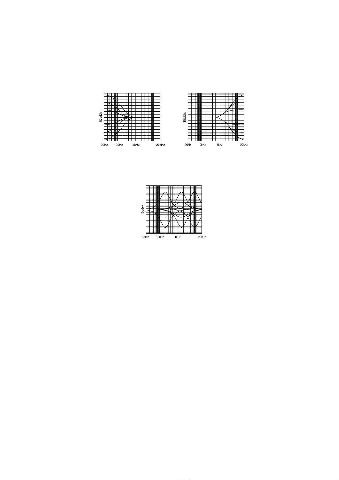
4.5.1 Equalizer (optional)
A three-band equalizer is available for input channel 1 and 2. Use the following controls to set
the equalizer according to your needs:
•80 Hz and 8 kHz: bass and treble adjustments are achieved by using two separate
±15 dB knobs.
•MF: medium frequencies adjustment is achieved by using one knob to progressively
adjust the central frequency from 180 Hz to 8 kHz, and by using another knob to
adjust the amplitude within a ±11 dB range.
4.6 Internal Settings
Please pay attention that these internal adjustments must be executed by a qualified technician
or by a SONOSAX appointed distributor or dealer. Any damage due to manipulations inside the
unit cancels the SONOSAX warranty immediately. See the appropriate schematic for proper
jumper or trimmer location.
To access all internal settings (jumpers and trimmers), you have to open and remove the
anodized cover located in the middle of the Bottom Panel (see 4.5). Simply unscrew the two
slotted screws present on the Bottom Panel and remove the anodized cover with care to avoid
damaging the cables and connectors that may be present if you have the optional equalizer
installed.
4.6.1 Headphones level adjustment
The two trimmers T3 (Left) and T4 (Right) located on top middle of the Front Board (see 5.4)
allow you to precisely adjust the nominal headphones output level The factory setting is 0dBu
for both channels on position 3.
NOTE: As all positions of the PHONES switch have a fixed step of 6dB among them, you only
have to adjust the nominal output level of position 3 to shift up or down the whole
output level range.
Table of contents
Other Sonosax Music Mixer manuals


