Sonotron NDT ISONIC utPod User manual

O
Op
pe
er
ra
at
ti
in
ng
g
M
Ma
an
nu
ua
al
l
R
Re
ev
vi
is
si
io
on
n
1
1.
.1
18
8
S
So
on
no
ot
tr
ro
on
n
N
ND
DT
T
I
IS
SO
ON
NI
IC
C
u
ut
tP
Po
od
d
U
Ul
lt
tr
ra
a-
-P
Po
or
rt
ta
ab
bl
le
e
M
Mu
ul
lt
ti
i-
-P
Pu
ur
rp
po
os
se
e
U
Ul
lt
tr
ra
as
so
on
ni
ic
c
T
Te
es
st
ti
in
ng
g
I
In
ns
st
tr
ru
um
me
en
nt
t

ISONIC utPod from Sonotron NDT - Operating Manual – Revision 1.18 - Page 2 of 94

ISONIC utPod from Sonotron NDT - Operating Manual – Revision 1.18 - Page 3 of 94
Information in this document is subject to change without notice. No part of this document may be
reproduced or transmitted in any form or by any means, electronic or mechanical, for any purpose, without
the express written permission of:
Sonotron NDT, 4, Pekeris st., Rabin Science Park, Rehovot, Israel, 76702
Covered by the United States patent 6545681; other US & foreign patents pending

ISONIC utPod from Sonotron NDT - Operating Manual – Revision 1.18 - Page 4 of 94
Sonotron NDT
4, Pekeris str., Rabin Science Park, Rehovot, 76702, Israel
Phone:++972-(0)8-9477701 Fax:++972-(0)8-9477712
http://www.sonotronndt.com
EC Declaration of Conformity
Council Directive 89/336/EEC on Electromagnetic Compatibility, as amended by
Council Directive 92/31/EEC & Council Directive 93/68/EEC
Council Directive 73/23/EEC ( Low Voltage Directive ), as amended by Council
Directive 93/68/EEC
We, Sonotron NDT Ltd., 4 Pekeris Street, Rehovot, 76702 Israel, certify that the product
described is in conformity with the Directives 73/23/EEC and 89/336/EEC as amended
ISONIC utPod
Ultra-Portable Multi-Purpose Ultrasonic Testing Instrument
The product identified above complies with the requirements of above EU directives by
meeting the following standards:
Safety
EN 61010-1:1993
EMC
EN 61326:1997
EN 61000-3-2:1995 /A1:1998 /A2:1998 /A14:2000
EN 61000-3-3:1995
ABCDEF

ISONIC utPod from Sonotron NDT - Operating Manual – Revision 1.18 - Page 5 of 94
Sonotron NDT
4, Pekeris str., Rabin Science Park, Rehovot, 76702, Israel
Phone:++972-(0)8-9477701 Fax:++972-(0)8-9477712
http://www.sonotronndt.com
EC Declaration of Conformity
Council Directive 89/336/EEC on Electromagnetic Compatibility, as amended by
Council Directive 92/31/EEC & Council Directive 93/68/EEC
Council Directive 73/23/EEC ( Low Voltage Directive ), as amended by Council
Directive 93/68/EEC
We, Sonotron NDT Ltd., 4 Pekeris Street, Rehovot, 76702 Israel, certify that the product
described is in conformity with the Directives 73/23/EEC and 89/336/EEC as amended
ISONIC utPod LF
Ultra-Portable Multi-Purpose Ultrasonic Testing Instrument Adapted for Low Frequency
Ultrasound Applications
The product identified above complies with the requirements of above EU directives by
meeting the following standards:
Safety
EN 61010-1:1993
EMC
EN 61326:1997
EN 61000-3-2:1995 /A1:1998 /A2:1998 /A14:2000
EN 61000-3-3:1995
ABCDEF

ISONIC utPod from Sonotron NDT - Operating Manual – Revision 1.18 - Page 6 of 94
FCC Rules
This ISONIC utPod / ISONIC utPod LF multi-functional ultrasonic testing instrument (hereinafter called ISONIC utPod / ISONIC utPod LF) has been
tested and found to comply with the limits for a Class B digital device, pursuant to Part 15 of the FCC Rules. These limits are designed to provide
reasonable protection against harmful interference in a residential installation. This equipment generates, uses and can radiate radio frequency energy
and, if not installed and used in accordance with the instructions, may cause harmful interference to radio communications. However, there is no guarantee
that interference will not occur in a particular installation. If this equipment does cause harmful interference to radio or television reception, which can be
determined by turning the equipment off and on, the user is encouraged to try to correct the interference by one or more of the following measures:
Reorient or relocate the receiving antenna
Increase the separation between the equipment and receiver
Connect the equipment into an outlet on a circuit different from that to which the receiver is connected
Consult the dealer or an experienced radio/TV technician for help
Safety Regulations
Please read this section carefully and observe the regulations in order to ensure your safety and operate the system as intended
Please observe the warnings and notes printed in this manual
The ISONIC utPod / ISONIC utPod LF has been built and tested according to the regulations specified in EN60950/VDE0805. It was in perfect working
condition on leaving the manufacturer's premises
In order to retain this standard and to avoid any risk in operating the equipment, the user must make sure to comply with any hints and warnings included
in this manual
Exemption from statutory liability for accidents
The manufacturer shall be exempt from statutory liability for accidents in the case of non-observance of the safety regulations by any operating person
Limitation of Liability
The manufacturer shall assume no warranty during the warranty period if the equipment is operated without observing the safety regulations. In any such
case, manufacturer shall be exempt from statutory liability for accidents resulting from any operation
Warranty
When used in accordance with the manufacturer’s written instructions and under normal operating conditions, ISONIC utPod / ISONIC utPod LF is
conditionally guaranteed to be free from defects in material and workmanship for a period of 12 months from date of shipment. Second year warranty
requires the instrument to be re-certified by Sonotron NDT or by an authorized representative or distributor, within 13 months of the date of purchase. A
normal recalibration and re-certification fee will apply. All repair work will be made ex-works at the factory premises or at the premises of authorized
representative or distributor provided the defective unit
is returned properly packed with all transportation charges prepaid. Any and all equipment replacement will be at the sole discretion of Sonotron NDT. This
warranty shall not apply to equipment subjected to misuse or abuse, improper installation, alteration, neglect, or accident
This warranty is limited to the original purchaser and is not transferable. No other warranty, expressed or implied, is made.
Exemption from warranty
The manufacturer shall be exempt from any warranty obligations in case of the non-observance of the safety regulations
The manufacturer will only warrant safety, reliability, and performance of the ISONIC utPod / ISONIC utPod LF if the following safety regulations are
closely observed:
Setting up, expansions, re-adjustments, alterations, and repairs must only be carried out by persons who have been authorized by manufacturer
The electric installations of the room where the equipment is to be set up must be in accordance with IEC requirements
The instrument must be operated in accordance with the instructions
Any expansions to the instrument must comply with the legal requirements, as well as with the specifications for the unit concerned
Confirm the rated voltage of you’re the instrument’s external AC/DC converter / charger matches the voltage of your power outlet
The mains socket must be located close to the instrument and must be easily accessible
Use only the power cord furnished with the instrument
Any required cable connectors must be hooked into the casing
The instrument must be disconnected from external AC/DC converter / charger before opening
To interrupt power supply, simply disconnect AC/DC converter / charger from the mains
Any balancing, maintenance, or repair may only be carried out by manufacturer authorized specialists who are familiar with the inherent dangers
If the instrument has suffered visible damage or if it has stopped working, it must be assumed that it could no longer be operated without any danger.
In these cases, the instrument must be switched off and be safeguarded against accidental use
Do not drop small objects, such as paper clips, into the instrument
Disconnect the power cord whenever a thunderstorm is nearby. Leaving the power cord connected may damage the instrument or your property
Do not allow any cables, particularly power cords, to trail across the floor, where they can be snagged by people walking past
Charge of the battery for the instrument is allowed only with use of the AC/DC converter / charger supplied along with it
Remember this before:
balancing
carrying out maintenance work
repairing
exchanging any parts
Software
ISONIC utPod / ISONIC utPod LF is a software controlled inspection device. Based on present state of the art, software can never be completely free of
faults. ISONIC utPod / ISONIC utPod LF should therefore be checked before and after use in order to ensure that the necessary functions operate
perfectly in the envisaged combination. If you have any questions about solving problems related to use the ISONIC utPod / ISONIC utPod LF, please e-

ISONIC utPod from Sonotron NDT - Operating Manual – Revision 1.18 - Page 7 of 94
1. INTRODUCTION .............................................................................................................................................................9
2. TECHNICAL DATA........................................................................................................................................................10
3. ISONIC UTPOD – SCOPE OF SUPPLY .......................................................................................................................11
4. OPERATING ISONIC UTPOD ......................................................................................................................................16
4.1. PRECONDITIONS FOR ULTRASONIC TESTING WITH ISONIC UTPOD..................................................................................16
4.1.1. General............................................................................................................................................................16
4.1.2. Training............................................................................................................................................................16
4.2. ISONIC UTPOD CONTROLS AND TERMINALS................................................................................................................17
4.3. TURNING ON /OFF ....................................................................................................................................................18
5. FLAW DETECTOR MODE ............................................................................................................................................20
5.1. TOP LEVEL SCREEN...................................................................................................................................................20
5.2. SUBMENU BASICS ...................................................................................................................................................20
5.2.1. Gain .................................................................................................................................................................21
5.2.2. Display Delay, Range, US Velocity ..................................................................................................................22
5.2.3. Reject ..............................................................................................................................................................22
5.2.4. AUTO CAL.......................................................................................................................................................23
5.3. SUBMENU PULSER ..................................................................................................................................................25
5.3.1. SINGLE / DUAL ...............................................................................................................................................25
5.3.2. Pulse Repetition Frequency (PRF ) .................................................................................................................25
5.3.3. Initial Pulse: Shape, Duration (Pulse Width), Firing Level................................................................................26
5.4. SUB MENU RECEIVER.............................................................................................................................................27
5.4.1. SINGLE / DUAL ...............................................................................................................................................27
5.4.2. Filter.................................................................................................................................................................27
5.4.3. Rectification .....................................................................................................................................................28
5.5. SUB MENUS GATE A/GATE B.................................................................................................................................29
5.5.1. Switch Gate ON / OFF.....................................................................................................................................29
5.5.2. Gate Start, Width, Threshold ...........................................................................................................................30
5.5.3. Draw Gate........................................................................................................................................................30
5.6. SUB MENU ALARM...................................................................................................................................................31
5.6.1. Switch Alarm ON / OFF ...................................................................................................................................31
5.6.2. Alarm Logic......................................................................................................................................................31
5.6.3. Alarm Example ................................................................................................................................................32
5.7. SUB MENU DAC .......................................................................................................................................................33
5.7.1. Theoretical DAC – dB/mm (dB/in)....................................................................................................................33
5.7.2. Experimental DAC: recording signals from variously located reflectors ...........................................................34
5.7.3. DGS.................................................................................................................................................................37
5.7.4. Multi-Curve DAC / DGS ...................................................................................................................................39
5.7.5. DAC Mode .......................................................................................................................................................40
5.8. SUB MENU MEASURE .............................................................................................................................................41
5.8.1. Probe Delay, Incidence Angle..........................................................................................................................41
5.8.2. X-Value............................................................................................................................................................41
5.8.3. Link Display Delay and Probe Delay Settings ..................................................................................................43
5.8.4. Value Being Measured ....................................................................................................................................44
5.8.5. Multiple Gate Measurements ...........................................................................................................................46
5.8.6. Flank and Top..................................................................................................................................................47
5.8.7. Geometry Corrections......................................................................................................................................48
5.8.8. Freeze, Freeze Peak, Locking Peak Envelop ..................................................................................................52
5.8.9. API Evaluation .................................................................................................................................................53
5.8.9.1. API-Evaluation: Standardization ...............................................................................................................53
5.8.9.2. API-Evaluation: Sizing Reflector ...............................................................................................................55
5.9. ZOOM A-SCAN ..........................................................................................................................................................56
5.10. 100 /110 %RANGE SWITCH....................................................................................................................................57
6. THICKNESS GAUGE MODE ........................................................................................................................................58
6.1. THICKNESS GAUGE START SCREEN ............................................................................................................................58
6.2. CALIBRATION –TOP LEVEL SCREEN ............................................................................................................................58
6.2.1. Probes With / Without Delay Line: Measurement Techniques .........................................................................59
6.2.2. Submenu BASICS ...........................................................................................................................................60
6.2.2.1. Gain, USVelocity, Reject, Range, Display Delay ......................................................................................60
6.2.2.2. Automatic Calibration................................................................................................................................61
6.2.3. Submenu PULSER ..........................................................................................................................................62
6.2.4. Submenu RECTIFY .........................................................................................................................................62

ISONIC utPod from Sonotron NDT - Operating Manual – Revision 1.18 - Page 8 of 94
6.2.5. Submenu GATE A ...........................................................................................................................................63
6.2.6. Min / Max .........................................................................................................................................................63
6.2.7. Data Logger.....................................................................................................................................................64
6.2.7.1. Defining Format of the Data Logger..........................................................................................................64
6.2.7.2. Filling Data Logger with Measurements Results .......................................................................................65
6.2.7.3. Exporting Data Logger File from ISONIC utPod to Computer...................................................................65
6.2.7.4. Emptying Data Logger Memory ................................................................................................................66
6.3. MEASUREMENT .........................................................................................................................................................67
6.3.1. Pure Digital / Combined Thickness Display .....................................................................................................67
6.3.2. Min/Max ...........................................................................................................................................................67
6.3.3. Data Logger.....................................................................................................................................................67
6.4. ZOOM A-SCAN ..........................................................................................................................................................67
7. CORROSION GAUGE MODE.......................................................................................................................................68
7.1. CORROSION GAUGE START SCREEN ...........................................................................................................................68
7.2. CALIBRATION –TOP LEVEL SCREEN ............................................................................................................................68
7.2.1. Measurement Techniques ...............................................................................................................................69
7.2.2. Submenu BASICS ...........................................................................................................................................70
7.2.2.1. Gain, USVelocity, Reject, Range, Display Delay ......................................................................................70
7.2.2.2. Automatic Calibration................................................................................................................................71
7.2.3. Submenu PULSER ..........................................................................................................................................72
7.2.4. Submenu RECTIFY .........................................................................................................................................73
7.2.5. Submenu GATE A ...........................................................................................................................................73
7.2.6. Min / Max .........................................................................................................................................................73
7.2.7. Data Logger.....................................................................................................................................................73
7.3. MEASUREMENT .........................................................................................................................................................74
7.3.1. Pure Digital / Combined Thickness Display .....................................................................................................74
7.3.2. Min/Max ...........................................................................................................................................................74
7.3.3. Data Logger.....................................................................................................................................................74
7.4. ZOOM A-SCAN ..........................................................................................................................................................74
8. ISONIC UTPOD FOR PC SW PACKAGE .....................................................................................................................75
8.1. ISONIC UTPOD –CONNECTION TO COMPUTER............................................................................................................75
8.2. ISONIC UTPOD INSTRUMENT CONTROL ......................................................................................................................75
9. MISCELLANEOUS ........................................................................................................................................................76
9.1. SETTINGS .................................................................................................................................................................76
9.2. ISONIC UTPOD VIEWER ............................................................................................................................................76
9.3. ISONIC UTPOD FIRMWARE UPDATE ...........................................................................................................................77
9.3.1. Prior to Updating..............................................................................................................................................77
9.3.2. Updating ISONIC utPod Firmware...................................................................................................................78
9.4. TOUCH SCREEN CALIBRATION ....................................................................................................................................79
9.5. BUILT-IN BUZZER ON/OFF ........................................................................................................................................81
9.6. BLANK SCREEN –SLEEP MODE ..................................................................................................................................82
10. ISONIC UTPOD REAL TIME LOGGER ......................................................................................................................83
10.1. GENERAL................................................................................................................................................................83
10.2. DOCKING TERMINAL.................................................................................................................................................83
10.3. OPERATING REAL TIME LOGGER ...............................................................................................................................86
10.3.1. Calibration......................................................................................................................................................86
10.3.2. New Real Time Log Record...........................................................................................................................89
10.3.2.1. Start Logging ..........................................................................................................................................90
10.3.2.2. Interrupt Logging Until it Started .............................................................................................................90
10.3.2.3. Finish Logging ........................................................................................................................................90
10.3.3. Overwriting Existing Log Record....................................................................................................................91
10.3.4. Delete Existing Log Record ...........................................................................................................................91
10.3.5. Download Log Record into Computer ............................................................................................................91

ISONIC utPod from Sonotron NDT - Operating Manual – Revision 1.18 - Page 9 of 94
1. Introduction
Ultra-portable Multi-Purpose Ultrasonic Testing Instrument ISONIC utPod uniquely comprises:
Top Performance Flaw Detector
All-Functional A-Scan Thickness Gauge
Simple Corrosion Gauge
Comprehensive Data Logger
ISONIC utPod is fully controllable from an external PC via USB
ISONIC utPod LF is a modified version of ISONIC utPod adopted for the low frequency ultrasound
applications. Comparing to ISONIC utPod it is characterized by the different frequency band and limits for
settling the duration of the initial pulse – refer to the Chapter 2 of present Operating Manual
ISONIC utPod ADL and ISONUC utPod LF ADL are the models additonally featured with the continous
automatic data logging function and docking terminal for integrating the instrument into autonomously
operating inspection systems – refer to the Chapter 10 of present Operating Manual

ISONIC utPod from Sonotron NDT - Operating Manual – Revision 1.18 - Page 10 of 94
2. Technical Data
Operating Modes: Flaw Detector
All-Functional A-Scan Thickness Gauge
Simple Corrosion Gauge
Initial Pulse Type:
Bipolar Square Wave Pulse
Initial Transition:
5 ns (10-90%)
Pulse Amplitude:
Smoothly tunable (12 levels) 60 V … 300 V pp into 50
Pulse Duration:
ISONIC utPod
ISONIC utPod LF
50…600 ns for each half wave synchronously controllable in 10 ns step
50…10000 ns (10 s) for each half wave synchronously controllable in 10 ns step
Modes:
Single / Dual
PRF:
15...2000 Hz controllable in 1 Hz resolution
Gain: 0...100 dB controllable in 0.5 dB resolution
Advanced Low Noise
Design:
81 V peak to peak input referred to 80 dB gain / 25 MHz bandwidth
Frequency Band:
ISONIC utPod
ISONIC utPod LF
0.2 … 25 MHz Wide Band
0.03 … 15 MHz Wide Band
Digital Filter: 32-Taps FIR band pass with controllable lower and upper frequency limits
Ultrasound Velocity: 300…20000 m/s (11.81…787.4 "/ms) controllable in 1 m/s (0.1 "/ms) resolution
Range: 0.5...7000 s controllable in 0.01 s resolution
Display Delay: 0...3200 s controllable in 0.01 s resolution
Probe Angle: 0…90ocontrollable in 1oresolution
Probe Delay: 0 to 70 s controllable in 0.01 s resolution
Display Modes: RF, Rectified (Full Wave / Negative or Positive Half Wave)
Reject: 0...99 % of screen height controllable in 1% resolution
DAC / TCG: Multi-curve (up to 4)
Theoretical – through keying in dB/mm (dB/") factor as used for AWS evaluation,
inspection of highly attenuative materials, and the like
Experimental – through recording echo amplitudes from variously distanced equal
reflectors, up to 40 points
46 dB Dynamic Range, Slope 120 dB/s
Available for Rectified and RF Display
DGS: Standard Library for 18 probes / expandable
Gates: 2 Independent Gates
Gate Start and Width: Controllable over the whole range of A-Scan time base settings
in 0.1 mm / 0.001" resolution
Gate Threshold: 5…95 % of A-Scan height controllable in 1 % resolution
Signal Evaluation – Digital
Readout:
19 automatic functions / expandable; curved surface / thickness / skip correction for
angle beam probes; material velocity and probe delay auto-calibration for all types of
probes; AWS / API evaluation
Freeze: Freeze All / Freeze Peak
Data Storage Capacity: At least 100000 sets including calibration dumps accompanied with A-Scans
Data Logger: 1D (linear), 2D (X, Y), 3D (X, Y, Z), or 4D (X, Y, Z, retake) array
Internal Flash Memory:
2 Gigabytes
Output: USB – calibration and data files transfer to / from PC, generation of inspection reports
in editable format and hard copy / full control by PC
Screen:
3.2" High Color Resolution QVGA Sun-Readable Active Matrix LCD with an embedded
PICASO-GFX2 graphics controller
Controls: Touch Screen
Power: On-board Li-Ion Rechargeable Battery, 6-10 hours continuous operation depending on
mode of use
Mains - External AC/DC converter / charger 100-240 VAC, 40-70 Hz
Housing: IP 67 rugged plastic case
Dimensions: 1308442 mm (5.12"3.31"1.65")
Weight: 400 g (0.88 lbs) - with battery
Hardware Warranty: 12 months
Firmware Warranty:
Lifetime free update with the latest version available for free access at
www.sonotronndt.com/support.htm
ISONIC utPod for PC
Software Warranty:
Lifetime free update with the latest version available for free access at
www.sonotronndt.com/support.htm
Available in three colors: Blue, Red, Black

ISONIC utPod from Sonotron NDT - Operating Manual – Revision 1.18 - Page 11 of 94
3. ISONIC utPod – Scope of Supply
# Item Order Code
(Part #)
Note
1 ISONIC utPod – Ultra-Portable Multi-Functional Ultrasonic
Testing Instrument
SA 80810
Including:
Top Performance Flaw Detector with DAC, DGS, TCG, Bipolar /
Unipolar Square Wave Pulser, 100 MHz Sampling Rate, 100 dB Analogue
Gain, AWS / API Evaluation
All-Functional A-Scan Thickness Gauge - Bipolar / Unipolar Square
Wave Pulser, 100 MHz Sampling Rate, 100 dB Analogue Gain, High
Precision
Use of single element probes with / without delay line
Through-Paint / Through Coating Thickness Measurement with use
of regular single element probes - no limit on the thickness of paint / coating
layer
Far Side Wall Thickness Measurement in tubes with use of regular
single element probes
Switchable into the simplest thickness gauge mode (digial readout
only)
All-Functional A-Scan Corrosion Gauge - Bipolar / Unipolar Square
Wave Pulser, 100 MHz Sampling Rate, 100 dB Analogue Gain, High
Precision
Use of dual element probes
Through-Paint / Through Coating Thickness Measurement with use
of regular single element probes - no limit on the thickness of paint / coating
layer
Far Side Wall Thickness Measurement in tubes with use of regular
single element probes
Switchable into the simplest corrosion gauge mode (digial readout
only)
Comprehensive Data Logger
Supervisor lock / unlock function
Full USB Controllability
ISONIC utPod for PC SW package (SW 808012) on the backup USB
key:
USB Connection to PC with live large high quality A-Scan /
instrument control over USB
Storing Calibrations / A-Scans / Data Logger files directly onto PCs
disk drive
Exporting Calibrations / A-Scans / Data Logger files from instrument
onto PCs disk drive
Importing Calibrations / A-Scans / Data Logger files from PCs disk
drive into instrument
Generating Inspection / Calibration Report - hard copy. PDF file,
editable MS Word file
Exporting Data Logger data Into Excel file
Operating Manual on the backup USB key
USB Cable for connection to the PC (S 808014)
Backup USB Key (S 808016)
Integrated Li-Ion Battery Pack (S 808018)
Stylus Stick (S 808020)
External charger with power cable (S 808022) - on-board battery
charging
2 G Internal Memory (SD Card)
400 g (0.88 lbs) including battery
12-month warranty for electronics and batteries
Lifetime free firmware upgrade for the instrument through
www.sonotronndt.com
Lifetime free software upgrade for the ISONIC utPod for PC SW
package through www.sonotronndt.com

ISONIC utPod from Sonotron NDT - Operating Manual – Revision 1.18 - Page 12 of 94
# Item Order Code
(Part #)
Note
2 ISONIC utPod LF – Ultra-Portable Multi-Functional Ultrasonic
Testing Instrument Adapted for Low Frequency Ultrasound
Applications
SA 80812
Including:
Top Performance Flaw Detector with DAC, DGS, TCG, Bipolar /
Unipolar Square Wave Pulser, 100 MHz Sampling Rate, 100 dB Analogue
Gain, AWS / API Evaluation
Extended Low Frequency Band - down to 30 kHz: 30 kHz ... 15
MHz
Expanded Range for Initial Pulse Width Tuning: 50 ns ... 10000 ns
(10 s)
All-Functional A-Scan Thickness Gauge - Bipolar / Unipolar Square
Wave Pulser, 100 MHz Sampling Rate, 100 dB Analogue Gain, High
Precision
Use of single element probes with / without delay line
Through-Paint / Through Coating Thickness Measurement with use
of regular single element probes - no limit on the thickness of paint / coating
layer
Far Side Wall Thickness Measurement in tubes with use of regular
single element probes
Switchable into the simplest thickness gauge mode (digial readout
only)
All-Functional A-Scan Corrosion Gauge - Bipolar / Unipolar Square
Wave Pulser, 100 MHz Sampling Rate, 100 dB Analogue Gain, High
Precision
Use of dual element probes
Through-Paint / Through Coating Thickness Measurement with use
of regular single element probes - no limit on the thickness of paint / coating
layer
Far Side Wall Thickness Measurement in tubes with use of regular
single element probes
Switchable into the simplest corrosion gauge mode (digial readout
only)
Comprehensive Data Logger
Supervisor lock / unlock function
Full USB Controllability
ISONIC utPod for PC SW package (SW 808012) on the backup USB
key:
USB Connection to PC with live large high quality A-Scan /
instrument control over USB
Storing Calibrations / A-Scans / Data Logger files directly onto PCs
disk drive
Exporting Calibrations / A-Scans / Data Logger files from instrument
onto PCs disk drive
Importing Calibrations / A-Scans / Data Logger files from PCs disk
drive into instrument
Generating Inspection / Calibration Report - hard copy. PDF file,
editable MS Word file
Exporting Data Logger data Into Excel file
Operating Manual on the backup USB key
USB Cable for connection to the PC (S 808014)
Backup USB Key (S 808016)
Integrated Li-Ion Battery Pack (S 808018)
Stylus Stick (S 808020)
External charger with power cable (S 808022) - on-board battery
charging
2 G Internal Memory (SD Card)
400 g (0.88 lbs) including battery
12-month warranty for electronics and batteries
Lifetime free firmware upgrade for the instrument through
www.sonotronndt.com
Lifetime free software upgrade for the ISONIC utPod for PC SW
package through www.sonotronndt.com

ISONIC utPod from Sonotron NDT - Operating Manual – Revision 1.18 - Page 13 of 94
# Item Order Code
(Part #)
Note
3 ISONIC utPod ADL – Ultra-Portable Multi-Functional Ultrasonic
Testing Instrument with Real Time Logger
SA 80814
Including:
Top Performance Flaw Detector with DAC, DGS, TCG, Bipolar /
Unipolar Square Wave Pulser, 100 MHz Sampling Rate, 100 dB Analogue
Gain, AWS / API Evaluation
All-Functional A-Scan Thickness Gauge - Bipolar / Unipolar Square
Wave Pulser, 100 MHz Sampling Rate, 100 dB Analogue Gain, High
Precision
Use of single element probes with / without delay line
Through-Paint / Through Coating Thickness Measurement with use
of regular single element probes - no limit on the thickness of paint / coating
layer
Far Side Wall Thickness Measurement in tubes with use of regular
single element probes
Switchable into the simplest thickness gauge mode (digial readout
only)
All-Functional A-Scan Corrosion Gauge - Bipolar / Unipolar Square
Wave Pulser, 100 MHz Sampling Rate, 100 dB Analogue Gain, High
Precision
Use of dual element probes
Through-Paint / Through Coating Thickness Measurement with use
of regular single element probes - no limit on the thickness of paint / coating
layer
Far Side Wall Thickness Measurement in tubes with use of regular
single element probes
Switchable into the simplest corrosion gauge mode (digial readout
only)
Comprehensive Data Logger
Automatic Real Time Logger
Docking Terminal for Integration into Autonomous Automatic Inspection
System
Supervisor lock / unlock function
Full USB Controllability
ISONIC utPod for PC SW package (SW 808012) on the backup USB
key:
USB Connection to PC with live large high quality A-Scan /
instrument control over USB
Storing Calibrations / A-Scans / Data Logger files directly onto PCs
disk drive
Exporting Calibrations / A-Scans / Data Logger files from instrument
onto PCs disk drive
Importing Calibrations / A-Scans / Data Logger files from PCs disk
drive into instrument
Generating Inspection / Calibration Report - hard copy. PDF file,
editable MS Word file
Exporting Data Logger data Into Excel file
Operating Manual on the backup USB key
USB Cable for connection to the PC (S 808014)
Backup USB Key (S 808016)
Integrated Li-Ion Battery Pack (S 808018)
Stylus Stick (S 808020)
External charger with power cable (S 808022) - on-board battery
charging
2 G Internal Memory (SD Card)
400 g (0.88 lbs) including battery
12-month warranty for electronics and batteries
Lifetime free firmware upgrade for the instrument through
www.sonotronndt.com
Lifetime free software upgrade for the ISONIC utPod for PC SW
package through www.sonotronndt.com

ISONIC utPod from Sonotron NDT - Operating Manual – Revision 1.18 - Page 14 of 94
# Item Order Code
(Part #)
Note
4 ISONIC utPod LF ADL – Ultra-Portable Multi-Functional
Ultrasonic Testing Instrument with Real Time Logger Adapted for
Low Frequency Ultrasound Applications
SA 80816
Including:
Top Performance Flaw Detector with DAC, DGS, TCG, Bipolar /
Unipolar Square Wave Pulser, 100 MHz Sampling Rate, 100 dB Analogue
Gain, AWS / API Evaluation
Extended Low Frequency Band - down to 30 kHz: 30 kHz ... 15
MHz
Expanded Range for Initial Pulse Width Tuning: 50 ns ... 10000 ns
(10 ms)
All-Functional A-Scan Thickness Gauge - Bipolar / Unipolar Square
Wave Pulser, 100 MHz Sampling Rate, 100 dB Analogue Gain, High
Precision
Use of single element probes with / without delay line
Through-Paint / Through Coating Thickness Measurement with use
of regular single element probes - no limit on the thickness of paint / coating
layer
Far Side Wall Thickness Measurement in tubes with use of regular
single element probes
Switcheable into the simplest thickness gauge mode (digial readout
only)
All-Functional A-Scan Corrosion Gauge - Bipolar / Unipolar Square
Wave Pulser, 100 MHz Sampling Rate, 100 dB Analogue Gain, High
Precision
Use of dual element probes
Through-Paint / Through Coating Thickness Measurement with use
of regular single element probes - no limit on the thickness of paint / coating
layer
Far Side Wall Thickness Measurement in tubes with use of regular
single element probes
Switcheable into the simplest corrosion gauge mode (digial readout
only)
Comprehensive Data Logger
Automatic Real Time Logger
Docking Terminal for Integration into Autonomous Automatic Inspection
System
Supervisor lock / unlock function
Full USB Controllability
ISONIC utPod for PC SW package (SW 808012) on the backup USB
key:
USB Connection to PC with live large high quality A-Scan /
instrument control over USB
Storing Calibrations / A-Scans / Data Logger files directly onto PCs
disk drive
Exporting Calibrations / A-Scans / Data Logger files from instrument
onto PCs disk drive
Importing Calibrations / A-Scans / Data Logger files from PCs disk
drive into instrument
Generating Inspection / Calibration Report - hard copy. PDF file,
editable MS Word file
Exporting Data Logger data Into Excel file
Operating Manual on the backup USB key
USB Cable for connection to the PC (S 808014)
Backup USB Key (S 808016)
Integrated Li-Ion Battery Pack (S 808018)
Stylus Stick (S 808020)
External charger with power cable (S 808022) - on-board battery
charging
2 G Internal Memory (SD Card)
400 g (0.88 lbs) including battery
12-month warranty for electronics and batteries
Lifetime free firmware upgrade for the instrument through
www.sonotronndt.com
Lifetime free software upgrade for the ISONIC utPod for PC SW
package through www.sonotronndt.com
ISONIC utPod from Sonotron NDT - Operating Manual – Revision 1.18 - Page 15 of 94
# Item Order Code
(Part #)
Note
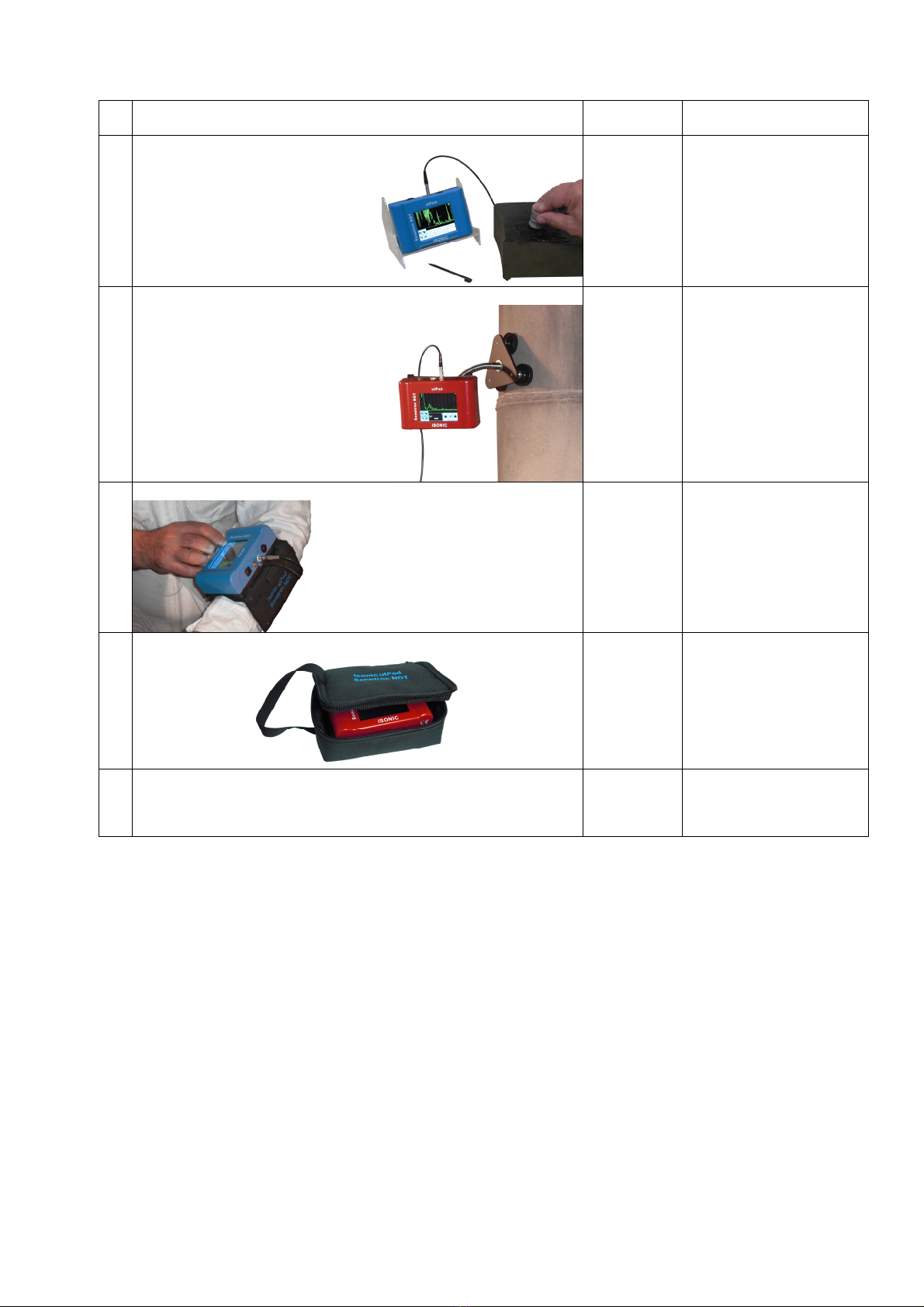
5 Table Stand for desktop usage of the ISONIC utPod S 808040 Optional Item
6 "Goose Neck" Adaptor S 808042 Optional Item
5 Arm Fixture for instrument usage in the field
S 808044 Optional Item
6 Soft case for ISONIC utPod S 808046 Optional Item
7 Ultrasonic probes, fixtures, scanners, cables and other
accessories depending on the inspection tasks to be resolved
Optional Items
Ultrasonic probes, fixtures,
scanners, cables and other
accessories from any manufacturer
may be used

ISONIC utPod from Sonotron NDT - Operating Manual – Revision 1.18 - Page 16 of 94
4. Operating ISONIC utPod
Please read the following information before you use ISONIC utPod. It is essential to read and understand
the following information so that no errors occur during operation, which could lead damaging of the unit or
misinterpretation of inspection results
4.1. Preconditions for ultrasonic testing with ISONIC utPod
4.1.1. General
The correct and effective use of ultrasonic test equipment requires the interaction of three factors:
The test equipment itself
The specific test applications
The operator
The purpose of this operating manual will be to give instructions in the basic set-up and functional operation
of ISONIC utPod. Such information is covered in detail within the manual. Other variable factors, some of
which are noted below, and the actions necessary to control them, are the responsibility of the user. Details
regarding these factors are beyond the scope of the operating manual
4.1.2. Training
The adequate training of the operators should be provided to assure competence in the operation of the
ISONIC utPod and in the associated factors. Operator of ISONIC utPod must be certified as at least Level 2
Ultrasonic Examiner. The operator must understand and provide for interpretation and compliance with the
specifications covering its work, generated by such groups as in-house Quality Assurance, Technical
Societies, Industry Groups, or Government Agencies

ISONIC utPod from Sonotron NDT - Operating Manual – Revision 1.18 - Page 17 of 94
4.2. ISONIC utPod Controls and Terminals
DC Charger Input
for Internal Battery
Battery
Charge
Status LED
RED – charging
GREEN - full
Sun Readable qVGA
Touch Screen
Power
Switch
Button
USB PortProbe Terminal 2Probe Terminal 1
ISONIC utPod from Sonotron NDT - Operating Manual – Revision 1.18 - Page 18 of 94
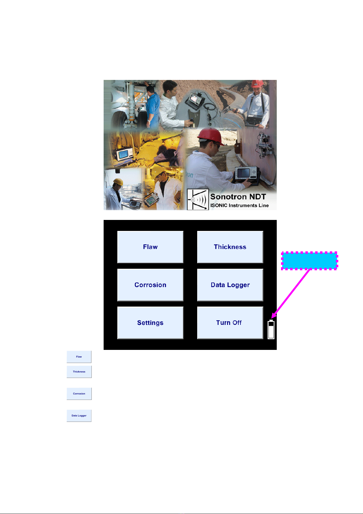
4.3. Turning On / Off
ISONIC utPod is powered by built-in rechargeable battery
To turn ISONIC utPod on press on power switch button. An automatic system test and boot-up routine will
be executed then indicating the screen as below
Wait until ISONIC utPod start screen appears upon boot-up completed:
Click on to operate ISONIC utPod as flaw detector (refer to chapter 5 of the operating manual)
Click on to operate ISONIC utPod as thickness gauge using single element probes (refer to
chapter 6 of the operating manual)
Click on to operate ISONIC utPod as corrosion gauge using dual element probes (refer to chapter
7 of the operating manual)
Click on to format data logger of ISONIC utPod (refer to chapter 8 of the operating manual)
Battery Status

ISONIC utPod from Sonotron NDT - Operating Manual – Revision 1.18 - Page 19 of 94
Click on in order to:
select measurement units (metric or imperial)
select the dialogue language
calibrate touch screen
switching built-in buzzer ON or OFF
setting power saving (sleep mode) parameters
identifying version (release number) of the currently installed firmware
Refer to Chapter 9 of present Operating Manual
To turn ISONIC utPod off click on or press power switch button during few seconds

ISONIC utPod from Sonotron NDT - Operating Manual – Revision 1.18 - Page 20 of 94
5. Flaw Detector Mode
5.1. Top Level Screen
Click on to store A-Scan
accompanied with signal evaluation
results and calibration set into a file
Click on to upload A-Scan
accompanied with signal evaluation
results and calibration set from a
file
Click on to freeze / return to
live A-Scan
Click on to return to upper
level menu. Current settings of flaw
detector will be kept as default then
5.2. Submenu BASICS
Click on in the Top Level Screen to enter, the screen as below appears
Table of contents
Popular Test Equipment manuals by other brands


ViewZ
ViewZ VZ-7IPTM user manual

Promax
Promax OL-612 user manual

Avtech
Avtech AVX-FILT Series instructions

Kyoritsu Electrical Instruments Works, Ltd.
Kyoritsu Electrical Instruments Works, Ltd. KEW 4506 instruction manual

Applied Instruments
Applied Instruments XR-3 Operation manual

Unit
Unit UT673A quick start guide

Metrix
Metrix GX-1030 user manual

Pro's Kit
Pro's Kit 8PK-4103IN manual

FRONIUS
FRONIUS Calibration system 2.0 operating instructions

Kyoritsu Electrical Instruments Works, Ltd.
Kyoritsu Electrical Instruments Works, Ltd. 4200 instruction manual

phase II+
phase II+ PHT-5000 Operation manual

Dilog
Dilog DL9120 operating instructions