Dilog DL9120 User manual

DL9120
DL9130EV
Multifunction
installation tester
Operating Instructions
Revision 1.2

DL9120 / DL9130 Operating Instructions
- 2 -
Figure 1 DL9120 / DL9130EV Overview

DL9120 / DL9130 Operating Instructions
- 3 -
Figure 2 Earth Continuity/Insulation Measurement
Figure 3 Voltage measurement using test probes

DL9120 / DL9130 Operating Instructions
- 4 -
Figure 4 Voltage, RCD, Zs and line impedance measurement at a
mains outlet
Figure 5 Voltage, RCD, Zs, Ze and line impedance measurement at a
distribution board

DL9120 / DL9130 Operating Instructions
- 5 -
Figure 6 Phase to phase impedance/PSC measurement (DL9130EV
only)
Figure 7 Phase rotation (DL9130EV only)

DL9120 / DL9130 Operating Instructions
- 6 -
Limited Warranty & Limitation of Liability
DI-LOG Test Equipment guarantees this product to be free from defects
in material and workmanship under normal use and service for a period
of 2 years. The period of warranty will be effective from the date of
purchase.
(c) Copyright 2022
All rights reserved. Nothing from this edition may be multiplied, or made
public in any form or manner, either electronically, mechanically, by
photocopying, recording, or in any manner, without prior written consent
from DI-LOG. This also applies to accompanying drawings and diagrams.
Due to a policy of continuous development, DI-LOG reserves the right to
alter the equipment specification and description outlined in this
publication without prior notice. No part of this publication shall be
deemed to be part of any contract for the equipment unless specifically
referred to as an inclusion within such contract.

DL9120 / DL9130 Operating Instructions
- 7 -
Table of Contents
Limited Warranty & Limitation of Liability............................................... 6
Table of Contents................................................................................... 7
Introduction............................................................................................ 9
1 User Notes....................................................................................... 10
2 Safety Notes .................................................................................... 11
3 Accessories...................................................................................... 12
3.1 Standard Accessories............................................................... 12
4 Unit Description................................................................................ 13
4.1 Identifying parts of the DL9120/DL9130EV............................... 13
4.2 LCD display .............................................................................. 14
5 Using the DL9120 / DL9130EV........................................................ 16
5.1 Power On.................................................................................. 16
5.2 Remote probe (only supplied with DL9130EV)......................... 16
5.3 Continuity Tests........................................................................ 17
5.4 Insulation Resistance Tests...................................................... 18
5.5 Voltage Measurement and Phase Rotation .............................. 20
5.6 Single Phase High Current Earth Loop Impedance / Line
Impedance....................................................................................... 20
5.7 Three Phase Line Impedance................................................... 22
5.8 Non trip Earth Loop Impedance / Line Impedance.................... 23
5.9 Auto RCD Test Sequence ........................................................ 25
5.10 Auto EV Test Sequence (DL9130EV only) ............................. 27
5.11 RCD Trip Time Tests (x1/2, x1 and x5) .................................. 30
5.12 RCD Variable Mode................................................................ 32
5.13 RCD trip current (Ramp) Tests............................................... 33
5.14 Warning / Test Active Indications............................................ 35
6 Electrical Specifications ................................................................... 36
6.1 Earth Continuity........................................................................ 36
6.2 Insulation Resistance................................................................ 36
6.3 Earth Loop Impedance ............................................................. 36
6.4 Line Impedance........................................................................ 37
6.5 RCD.......................................................................................... 37
6.6 RDC-DD (DL9130EV only) ....................................................... 37
6.7 Voltage/Frequency Measurement............................................. 37
7 Environmental Conditions................................................................ 38
8 Maintenance .................................................................................... 39
8.1 Preparing to work on the DL9120 / DL9130EV......................... 39
8.2 Securing the DL9120 / DL9130EV............................................ 39
8.3 Cleaning ................................................................................... 39
8.4 Battery Replacement................................................................ 40
8.6 Service and Calibration............................................................. 41
8.7 Spare Parts............................................................................... 42

DL9120 / DL9130 Operating Instructions
- 8 -
Disposal of Old Product
This product has been designed and manufactured with high quality
materials and components that can be recycled and reused.
Please familiarise yourself with the appropriate local separate collection
system for electrical and electronic products.
Please dispose of this product according to local regulations. Do not
dispose of this product along with normal waste material. The correct
disposal of this product will help prevent potential negative consequences
for the environment and human health.

DL9120 / DL9130 Operating Instructions
- 9 -
Introduction
The DL9120 / DL9130EV is a handheld, battery powered, multi-function
electrical installation test instrument capable of performing a
comprehensive range of tests, including:
Earth Continuity @ 200mA
Earth Continuity @ 15mA (DL9130EV only)
Insulation Resistance at 250V, 500V and 1000V
Voltage
Frequency
Phase rotation
RCD Trip Time at ½In, In and 5xIn
RCD Trip current
RCD Type A, AC and B
RDC-DD testing (DL9130EV only)
Variable RCD test currents
Non trip Zs and PFC measurement on RCD protected circuits
High current Ze and PFC on non RCD protected circuits
Phase to neutral impedance and PSC
Phase to phase impedance and PSC
Power socket wiring polarity

DL9120 / DL9130 Operating Instructions
- 10 -
1User Notes
This instrument and its operating instructions are intended for use
by trained personnel.
The following symbols are used in these operating instructions and on the
DL9120 / DL9130EV.
Warning of electrical danger!
Indicates instructions must be followed to avoid danger to
persons.
Important, follow the documentation! This symbol indicates that
the operating instructions must be consulted and adhered to in
order to avoid danger.

DL9120 / DL9130 Operating Instructions
- 11 -
2Safety Notes
This DL9120 / DL9130EV is fully compliant with the requirements of:
BS EN 61010-1
BS EN 61010-2-30
BS EN 61557 part 1, 2, 3, 4, 6, 7 and 10.
In order to ensure safe operation of this instrument, all notes and
warnings in these instructions must be observed at all times.
The DL9120 / DL9130EV has been designed to make
measurements in a dry environment.
The DL9120 / DL9130EV may be used to test circuits with
a maximum over-voltage Category III, 300 V AC/DC with
reference to earth.
When making connections using the test probes always
hold test probes above the hand guards.
The DL9120 / DL9130EV and all associated cables and
leads must be checked for signs of damage before
equipment is operated.
Prior to any resistance measurement, always ensure that
the circuit under test is electrically isolated.
Where safe operation of the DL9120 / DL9130EV is no longer possible it
should be immediately shut down and secured to prevent accidental
operation.
It must be assumed that safe operation is no longer possible:
- if the instrument or leads show visible signs of damage or
- the instrument does not function or
- after long periods of storage under adverse environmental conditions.
If the DL9120 / DL9130EV is used in a manner not specified
by this document, then the protection provided by the
equipment may be impaired.

DL9120 / DL9130 Operating Instructions
- 12 -
3Accessories
3.1 Standard Accessories
The DL9120 / DL9130EV is supplied with the following items:
DL9120 or DL9130EV unit
Padded neck strap
Professional carry case
DI-LOG mains lead
1.2 M blue test lead
1.2 M red test lead
1.2 M green test lead
Blue crocodile clip
Red crocodile clip
Green crocodile clip
Remote probe with test button (DL9130EV only)
MN1500 (AA) 1.5v Batteries x 6
Spare 500mA 1000V HRC FF Fuse
Operating Instruction Manual
Calibration certificate
Do not open unit, no other serviceable parts.

DL9120 / DL9130 Operating Instructions
- 13 -
4 Unit Description
The DL9120 / DL9130EV is a handheld, multi-function electrical
installation test instrument, capable of performing all of the required
electrical tests. Tests are selected using the colour coded rotary switch.
4.1 Identifying parts of the DL9120/DL9130EV
The numbering below refers to figure. 1
1. Rotary Switch
a. Voltage, Frequency and Phase Rotation
b. Insulation resistance @ 1000V
c. Insulation resistance @ 500V
d. Insulation resistance @ 250V
e. Continuity @ 200mA or 15mA
f. Off
g. High current Ze/Zs and PSC/PFC
h. Non-trip Zs and PFC
i. Auto RCD sequence (EV only on DL9130EV)
j. RCD trip time @ ½ IN
k. RCD trip time @ IN
l. RCD trip time @ 5IN
m. Variable RCD
n. RCD trip current (ramp test)
2. LCD Display
3. Function keys F1, F2, F3 and F4
4. TEST key
5. Test lead input (RED) –Mains Live, Continuity/Insulation +
6. Test lead input (GREEN) –Mains Earth, Continuity/Insulation -
7. Test lead input (BLUE) –Mains Neutral
Note: Rotating the Rotary Switch through the off position
without stopping will maintain the power on the DL9120 /
DL9103EV.
Note: The DL9120 / DL9130EV will power off if it is inactive for a
period of time. In order to re-power the DL9120 / DL9130EV
you must rotate the Rotary Switch to off then rotate the
Rotary Switch to the required test position.
Note: The function performed by keys F1 –F4 depends upon the
rotary switch position. For each rotary switch position, the
left hand side of the LCD display indicates the function of
the key above.
DL9120 / DL9130 Operating Instructions
- 14 -
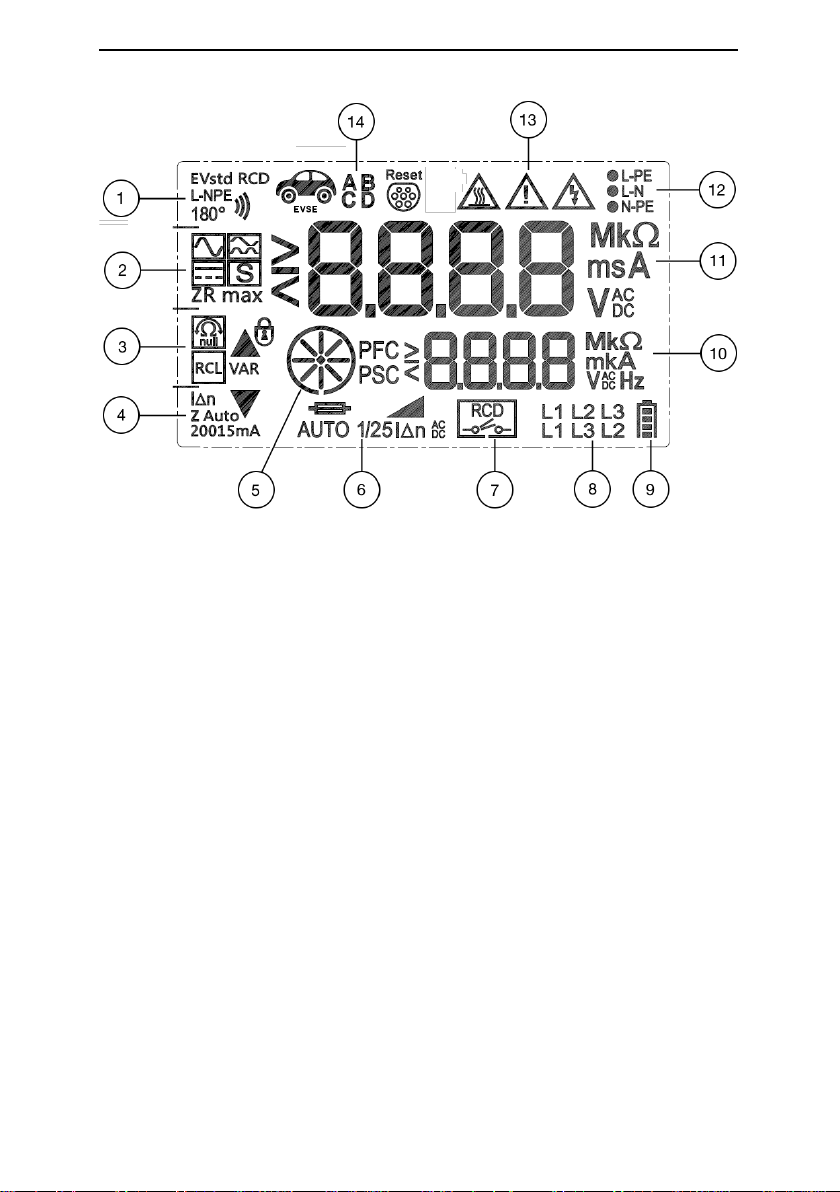
4.2 LCD display
1. Icons for function key F1. These icons are used to display the
available options for the selected test. Repeatedly pressing
function key F1 cycles through the available options.
2. Icons for function key F2. These icons are used to display the
available options for the selected test. Repeatedly pressing
function key F2 cycles through the available options.
3. Icons for function key F3. These icons are used to display the
available options for the selected test. Repeatedly pressing
function key F3 cycles through the available options.
4. Icons for function key F4. These icons are used to display the
available options for the selected test. Repeatedly pressing
function key F4 cycles through the available options.
5. Zs/Ze progress indicator / Phase sequence indicator
6. RCD test icons. These icons display the selected RCD test
function.
7. RCD status. Indicates when the RCD has tripped during an RCD
test.
8. Phase sequence indicator
9. Battery status indicator. Shows the amount of charge in the
batteries.
10. Secondary display.
11. Primary display
12. Mains supply status icons. These icons indicate the status of the
mains supply between line and earth (L-PE), line and neutral (L-
N) and neutral and earth (N-PE) during RCD and Loop tests.

DL9120 / DL9130 Operating Instructions
- 15 -
Note: Testing is inhibited if the mains supply is incorrect.
13. Warning Icons. These icons are used to inform the user of the
potential of any hazard or warning which may restrict the
operation of the DL9120 / DL9130EV. Details are provided in the
relevant parts of these operating instructions.
14. EVSE status icons.

DL9120 / DL9130 Operating Instructions
- 16 -
5 Using the DL9120 / DL9130EV
5.1 Power On
To turn the DL9120 / DL9130EV on, simply rotate the rotary switch to the
required test position, the DL9120 / DL9130EV will display the battery
voltage for a short period of time.
Backlight Functionality (Power On with F1 pressed)
If F1 is held down when turning on the DL9120 / DL9130EV then the
backlight options will be displayed. The DL9120 / DL9130EV will display
bL and the existing setting, pressing F1 will cycle through the available
options;
OFF - Backlight functionality is disabled
bLUE - The backlight is always set to blue
rGb - LCD backlight is set to blue but will change to green for
passed measurements and red for failed measurements.
Press the test key to store the displayed option.
Battery Health Check
The DL9120 / DL9130EV will automatically perform battery health checks
at power on and periodically while the DL9120/ DL9130EV is being used.
Note: When the battery symbol is flashing all tests will be inhibited
and the batteries should be replaced as described in section
8.4.
Note: The battery health check may indicate that the batteries are
healthy but stop tests with a flashing battery symbol during
testing. This is due to the different levels of current required
during different test types. The batteries should be replaced
as described in section 8.4.
5.2Remote probe (only supplied with DL9130EV)
The remote probe can be used in place of the standard 4mm red test
lead. When the remote probe is connected, the TEST button on the probe
performs the same function as the TEST key on the DL9120 / DL9130EV.
Either TEST button/key can be used to initiate a measurement.

DL9120 / DL9130 Operating Instructions
- 17 -
5.3Continuity Tests
Always ensure that the circuit under test is electrically
isolated.
Measurements can be adversely affected by impedances
of additional operating circuits connected in parallel or by
transient currents.
If the test probes are connected across a voltage of >30V
ac/dc then the DL9120 / DL9130EV will automatically
display the voltage between the probes, the warning buzzer
will sound.
Rotate the rotary switch until the Continuity test is selected.
When the continuity test is selected, the DL9120 / DL9130EV will display
the user selectable test options for a short period of time; Buzzer, R max,
Lead Zero and 15/200mA (15mA DL9130EV only). If the Buzzer or Lead
Zero was previously enabled, then the icon will remain on the display
when the continuity test is selected. If the Lead Zero is disabled then the
icon will flash to indicate that the leads should be zeroed, if the Buzzer or
R max are disabled then the icons will not be displayed.
Functions keys F1-F4 have are used to select the options below:
F1
F2
(DL9130EV)
F3
F4
Buzzer
R max
Lead Zero
200 / 15mA
(DL9130EV)
Buzzer (F1)
When enabled, the Buzzer will sound when the continuity measurement
is less than 20 ohms.
R max (F2, DL9130EV only)
When enabled, the DL9130EV will record the highest continuity
measurement taken. This will be displayed in the secondary display.
When this function is disabled, the maximum recorded value is reset.
Lead Zero (F3)
The instrument can automatically compensate for the resistance of the
test leads as follows:
Fit the supplied crocodile clips tothe red and green test leads and connect
the crocodile clips firmly together using both lower parts of the jaw. Press

DL9120 / DL9130 Operating Instructions
- 18 -
and hold the Lead Zero (F3). The measured resistance of the test leads
is shown in the primary display until a beep is heard and the Lead Zero
icon is shown on the display. All subsequent measurements will
automatically include compensation for the test lead resistance. To
disable the function, remove the leads from the load to measure open
circuit, press and hold F3.
Note: A maximum test lead resistance of 10 ohms can nulled out. If
the test lead resistance is greater than 10 ohms an error beep
will indicate that the Lead Zero function has failed, and the
display icon will not be shown.
Note: For ease of use, the DL9120 / DL9130EV will store the Lead
Zero compensation when switched off and recall this value
when next switched on. The stored value is only applicable to
the test leads used when the compensation measurement was
made. If the test leads are replaced the Lead Zero function
should be repeated using the replacement test leads.
200mA / 15mA Test Current (F4, DL9130EV only)
The DL9130EV can perform Continuity tests at both 200mA and 15mA.
To switch between the currents the test probes must be open circuit.
Press F4 until the required test current is displayed.
The DL9120 can only perform tests at 200mA.
TEST
The Continuity test does respond to the TEST key or Remote probe
button, the test will automatically start when a low resistance is detected.
5.4Insulation Resistance Tests
Always ensure that the circuit under test is electrically
isolated.
Should a voltage of >30V be applied to the DL9120 /
DL9130EV while in Insulation mode the DL9120 /
DL9130EV will enter Voltage mode until the voltage is
removed.
If the test probes are connected across a voltage of >30V
then the DL9120 / DL9130EV will automatically display the
voltage between the probes, the warning buzzer will sound
and the TEST key is inhibited.

DL9120 / DL9130 Operating Instructions
- 19 -
The DL9120 / DL9130EV will discharge any charged
voltage that has been generated due to the insulation test
as long as the DL9120 / DL9130EV remains connected to
the circuit under test after the test is complete. If the
charged voltage is hazardous at the end of the test the
DL9120 / DL9130EV will enter voltage mode until the
voltage is below 30V.
Should the DL9120 / DL9130EV be removed from the
circuit under test during an active Insulation test then any
charged voltage CANNOT NOT be discharged by the
DL9120 / DL9130EV.
Use the rotary switch to select either the 250V, 500V or 1000V M
(DL9130EV only) test.
The DL9120 / DL9130EV will display the Test Lock and battery symbol
for 1 second. If the Test Lock feature is required, it should be activated
as described below.
Functions keys F1-F4 have are used to select the options below:
F1
F2
F3
F4
Buzzer
Not Used
Test Lock
Not used
Buzzer (F1)
When enabled, the Buzzer will sound when the continuity measurement
is less than or equal to 1Mohm.
Test Lock (F3)
The Test Lock is used to ‘lock’ the DL9120 / DL9130EV in a continuous
measurement mode, with a single press of the TEST key. When Test
Lock is enabled, the LCD shows the padlock icon. When Test Lock is
active the TEST key is locked until the option is disabled or the rotary
switch is moved to another position.
To enable the Test Lock mode, press the F3 key before the TEST key is
pressed or press F3 and the TEST simultaneously.
To disable Test Lock, press F3 or turn the rotary switch to another
position.
TEST
To make an insulation resistance measurement, press the TEST key.
When a single press is made, the test willstart for a duration of 3seconds.
If the TEST key is held down, the test will continue until the TEST button
is released. Alternatively, use the Test Lock function to allow

DL9120 / DL9130 Operating Instructions
- 20 -
measurements to be started or stopped with a single press of the TEST
key.
During a measurement, the measured value is shown in the primary
display and the measured test voltage is shown in the secondary display.
5.5Voltage Measurement and Phase Rotation
F1
F2
F3
F4
Not Used
Not Used
Not Used
Not used
Rotate the rotary switch until the V test is selected. The DL9120 /
DL9130EV will automatically measure any voltage present on the test
probes. The TEST key is not required.
The function keys do not perform any operations while in Voltage mode.
When an AC voltage is applied to the test probes, the frequency of the
measured voltage is shown in the secondary display.
The voltage displayed will be the larger of voltages connected across the
RED-BLUE or RED-GREEN test terminals, the connections used to
display the voltage will also be indicated on the LCD.
When a 3 phase voltage is connected to the test probes, the voltage
between the red and black is displayed in the primary display and the
phase sequence icon is shown on the display. When the test probes are
connected as follows: RED to L1, GREEN to L2, BLACK to L3 the display
icon will show L1 L2 L3.
5.6Single Phase High Current Earth Loop Impedance /
Line Impedance
The DL9120 / DL9130EV will only allow the Earth Loop
Impedance test to be performed if the correct voltages are
detected between line-earth (L-PE illuminated), line-neutral
(L-N illuminated) and neutral-earth (N-PE not illuminated).
When performing 2 wire tests and under certain
circumstances, a potential hazardous touch voltage could
be determined due to the impedance of the circuit under
test, the DL9120/9130 will stop the test immediately
indicating “3 LEAd”. If this happens, connect all three
This manual suits for next models
1
Table of contents
Other Dilog Test Equipment manuals


