Sony Ericsson GR48 Instruction Manual

GR 47/GR 48
Design Guidelines

CE
The product described in this manual conforms to the TTE directive 91/263/EEC and EMC directive
89/336/EEC. The product fulfils the requirements according to ETS 300 342-1.
The information contained in this document is the proprietary information of Sony Ericsson Mobile
Communications. The contents are confidential and any disclosure to persons other than the officers,
employees, agents or subcontractors of the owner or licensee of this document, without the prior written
consent of Sony Ericsson Mobile Communications, is strictly prohibited.
Further, no portion of this publication may be reproduced, stored in a retrieval system, or transmitted in
any form or by any means, electronic or mechanical, including photocopying and recording, without the
prior written consent of Sony Ericsson Mobile Communications, the copyright holder.
First edition (May 2003)
Sony Ericsson Mobile Communications. publishes this manual without making any warranty as to the
content contained herein. Further Sony Ericsson Mobile Communications. reserves the right to make
modifications, additions and deletions to this manual due to typographical errors, inaccurate information,
or improvements to programs and/or equipment at any time and without notice. Such changes will,
nevertheless be incorporated into new editions of this manual.
All rights reserved.
©Sony Ericsson Mobile Communications., 2003

GR47/48 Design Guidelines
BA/SEM/MS 03:0015 Rev ALZT 123 7596 3
Contents
1INTRODUCTION....................................................................................................................5
1.1 OVERVIEW.........................................................................................................................5
1.2 PRECAUTIONS ...................................................................................................................5
1.3 ABBREVIATIONS.................................................................................................................5
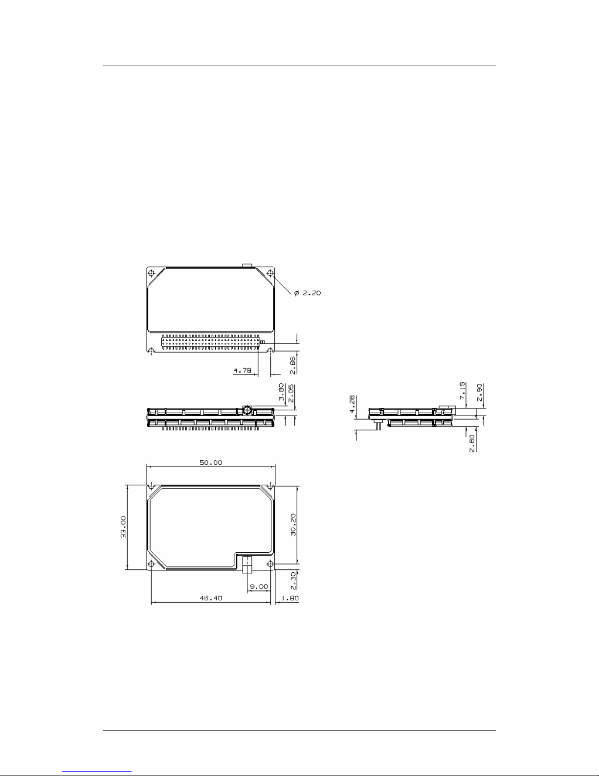
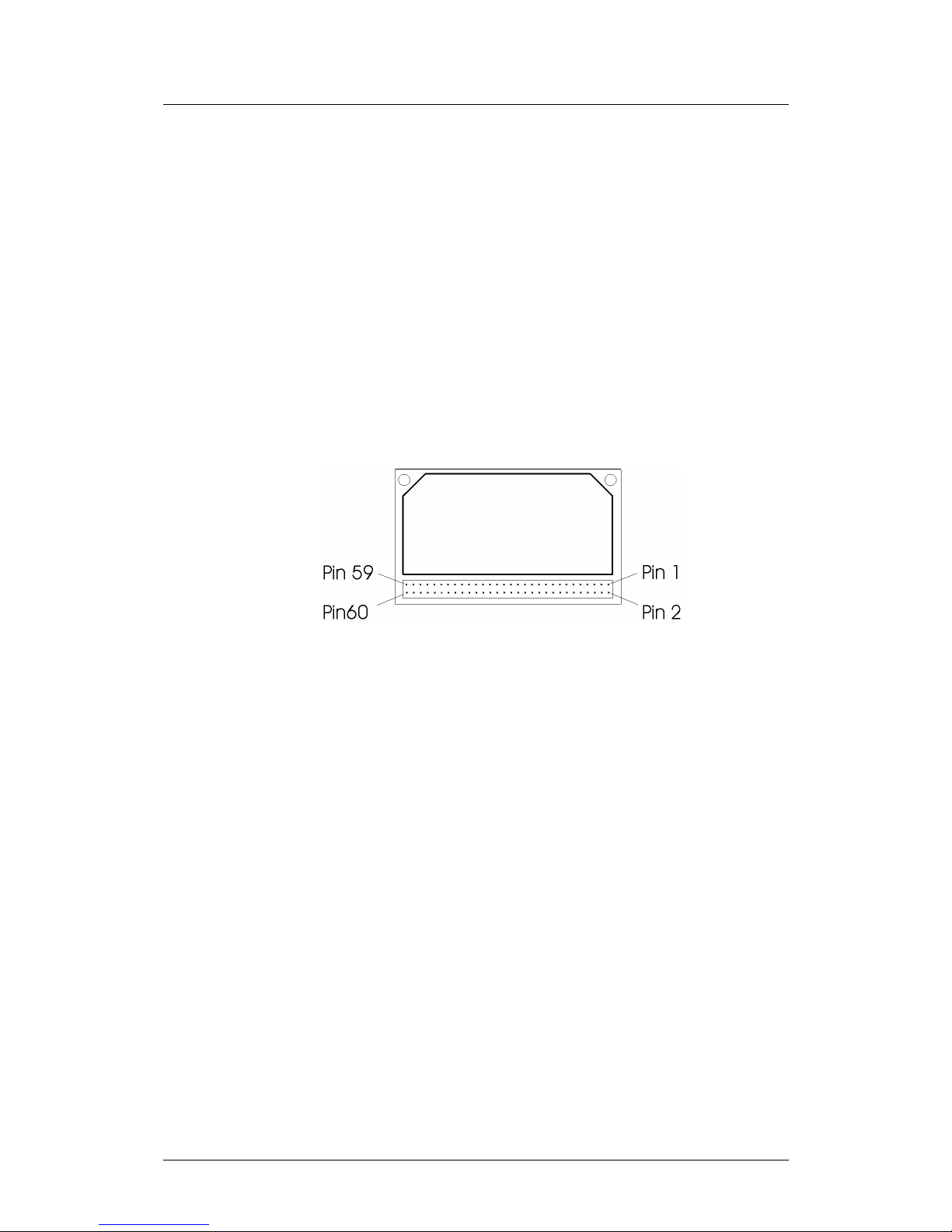
2MECHANICAL INTEGRATION..............................................................................................7
2.1 PHYSICAL DIMENSIONS ......................................................................................................7
3ELECTRICAL INTEGRATION...............................................................................................8
3.1 GENERAL ..........................................................................................................................8
3.2 GROUNDING......................................................................................................................9
3.2.1 The Analogue Ground..............................................................................................9
3.2.2 The Digital Ground (DGND).....................................................................................9
3.3 EXTERNAL SUPPLY TO MODULE........................................................................................10
3.3.1 Power Supply (VCC)..............................................................................................10
3.3.2 General Recommendations ...................................................................................11
3.3.3 On/Off signal ..........................................................................................................13
3.4 SIM CONNECTIONS..........................................................................................................14
3.5 AUDIO CONNECTIONS ......................................................................................................15
3.5.1 Analogue Audio......................................................................................................15
3.5.2 Advanced Portable Hands Free Functionality........................................................16
3.6 RF AND ANTENNA INTEGRATION........................................................................................17
3.7 INTERFACING TO A 3.3V µPROCESSOR.............................................................................18
3.8 SOFTWARE DOWNLOAD AND LOGGING CIRCUITRY..............................................................19
4DEVELOPERS BOARD.......................................................................................................21
4.1 POWER CIRCUIT ..............................................................................................................21
4.2 SIM CIRCUIT ...................................................................................................................21
4.3 ON/OFF SWITCH ..............................................................................................................21
4.4 PROGRAMMING CIRCUITRY...............................................................................................21
4.5 EMC...............................................................................................................................22
4.6 DATA SIGNALS:................................................................................................................22
5PART NUMBERS.................................................................................................................23
5.1 SYSTEM CONNECTOR.......................................................................................................23
5.2 RF CONNECTOR ..............................................................................................................23
5.3 SIM CARD HOLDER ..........................................................................................................23
5.4 SUPPLIERS......................................................................................................................23
5.4.1 Imperial connectors................................................................................................23
5.4.2 IMS connectors ......................................................................................................24
6TYPE APPROVAL ...............................................................................................................25
6.1 DOCUMENTATION REQUIRED.............................................................................................25
6.2 POWER SUPPLY...............................................................................................................26
6.3 SIM TESTING ..................................................................................................................27
6.4 EMC/ESD &SAFETY ......................................................................................................27
6.5 RF TESTING....................................................................................................................27
6.5.1 GR47......................................................................................................................27
6.5.2 GR48......................................................................................................................28
6.6 SAR WARNING ................................................................................................................28
6.7 OTHER TAISSUES ...........................................................................................................28
6.7.1 External Application software.................................................................................28

GR47/48 Design Guidelines
BA/SEM/MS 03:0015 Rev ALZT 123 7596 4
6.7.2 GR47 software updates .........................................................................................28
APPENDIX I -TECHNICAL DATA .............................................................................................29
APPENDIX II –GR47/GR48PIN OUT.........................................................................................31
APPENDIX III GSM TRANSMIT WAVEFORM CHARACTERISTICS........................................34

GR47/48 Design Guidelines
BA/SEM/MS 03:0015 Rev ALZT 123 7596 5
1Introduction
1.1 Overview The GR47/GR48belong to a new generation of Sony Ericsson Mobile
Communications GSM modules. This document describes the main
characteristics and functionality of the GR 47/48, two dual band
products for 900/1800 MHz and 850/1900 MHz GSM bands
respectively.
This document should be used in conjunction with either the GR 47/48
Integrators Manual or GR47/GR48Technical Description and is
intended to aid the system integrator both designing the module into
their application and gaining the correct approvals.
1.2 Precautions The GR47/GR48are static sensitive devices (SSD’s). Normal SSD
procedures for electronic devices should be used when handling the
modules. In the Integrators’ Manual you will find more information
about safety and product care. Never exceed these limits to ensure the
module is not damaged.
1.3 Abbreviations
Abbrevi
ation
Explanation
BT Bluetooth
CBS Cell Broadcast Service
CBM Cell Broadcast Messaging
CSD Circuit Switch Data
DCE Data Circuit Terminating Equipment
DTE Data Terminal Equipment
DTMF Dual Tone Multi Frequency
EFR Enhanced Full Rate codec
EMC Electro-Magnetic Compatibility
ETSI European Telecommunications Standards Institute
FR Full Rate codec
GPRS General Packet Radio Service
GPS Global Positioning System
GSM Global System for Mobile Comunication
HR Half Rate codec
HSCSD High Speed Circuit Switched Data
ITU-T International Telecommunication Union –Telecommunications
Standardisation Sector

GR47/48 Design Guidelines
BA/SEM/MS 03:0015 Rev ALZT 123 7596 6
ME Mobile Equipment
MO Mobile Originated
MS Mobile Station
MT Mobile Terminated
PCM Pulse Code Modulation
PDU Protocol Data Unit
RLP Radio Link Protocol
RF Radio Frequency
RTC Real Time Clock
SDP Service Discovery Protocol
SMS Short Message Service
SIM Subscriber Identity Module
TBD To Be Defined

GR47/48 Design Guidelines
BA/SEM/MS 03:0015 Rev ALZT 123 7596 7
2Mechanical Integration
The GR 47/48 is protected with AISI 304 Stainless Steel covers
suitable to fulfil the environmental and EMC requirements.
The position of the different connectors and mounting holes are shown
in figure 2.1 with dimensions.
2.1 Physical Dimensions
Figure 2.1 Physical dimensions of GR 47/48

GR47/48 Design Guidelines
BA/SEM/MS 03:0015 Rev ALZT 123 7596 8
3Electrical Integration
3.1 General
The electrical connections to the module (except the antenna), are set
through the System Connector Interface.
The connector allows the following connections:
•board to board.
•board to cable.
See section 5 for suppliers and part numbers.
The figure 3.1 below indicates the pin numbering scheme.
Figure 3.1 GR 47/48. View from the underside

GR47/48 Design Guidelines
BA/SEM/MS 03:0015 Rev ALZT 123 7596 9
3.2 Grounding
Pins Name Description
2, 4, 6, 8, 10, 12 DGND Digital Ground
60
AGND
Analogue Ground
There are two ground signals in GR 47/48, Analogue Ground (AGND)
and Digital Ground (DGND). The analogue Ground is connected to pin
number 60, and the Digital Ground is connected to the System
Connector Interface through pin numbers 2, 4, 6, 8, 10 and 12.
Note: All the Ground pins have to be connected to the application. The
AGND is connected to the DGND in the ME, and only there. It is
important that the AGND and the DGND are separated in the
application.
3.2.1 The Analogue Ground
The AGND lead is the analogue audio reference ground. It is the return
signal for Audio To Mobile Station (ATMS) and Audio From Mobile
Station (AFMS).
It is connected to the Digital Ground (DGND) inside the module and
only there. The application shall not connect DGND and AGND.
Parameter Limit
Imax ≅12.5mA
3.2.2 The Digital Ground (DGND)
DGND is the reference for all digital signals in the System Interface.
It shall also be the DC return for the power supply on VCC and
SERVICE. Each DGND pin is rated at 0.5 A. All DGND pins are
connected internally in the module.
Parameter Limit
Iaverage < 0.5 A No DGND pin can withstand over 0.5 A
Imax < 600 mA (100 mA each)

GR47/48 Design Guidelines
BA/SEM/MS 03:0015 Rev ALZT 123 7596 10
3.3 External Supply to Module
Pins Name Description
1, 3, 5, 7, 9, 11 VCC Regulated Power Supply
Connect all of the pins together in the application in order to carry the
current drawn by the module.
3.3.1 Power Supply (VCC)
The VCC supplies the module with external power. Any other voltage
needed is generated internally.
Parameter Mode Limit
Voltage to be applied Nominal 3.6 Volts
Tolerance 3.4 Volts -4.0 Volts
Maximum voltage drop during
transmit burst 200mV
Over voltages 5.5 Volts
Current Drive capability at TX Full Power < 600 mA (average))
< 2 A (Peak)

GR47/48 Design Guidelines
BA/SEM/MS 03:0015 Rev ALZT 123 7596 11
GR 47/48 does not have internal capacitance to supply the large current
peaks during GSM transmission. Therefore on burst transmission the
application DC source is responsible for providing the appropriate
current.
Recommendations to the design of power supplies are given in the
following paragraphs.
V1
3.6V
C1
220uF CF
100uF
Low ESR
CBULK
1000uF
Low ESR
RLINE
100mohm
RRX
120ohm
30mA Load
RTX
1.8ohm
2A Load
J1
577usec
1:8 Duty Cycle
'RLINE' represents resistance
of circuit between PSU and
GM47/GM48.
L1
33uH
+
+
+
2 Amp
Vcc
Figure 3.2 -Simplified Power Supply Reference Model
3.3.2 General Recommendations
The power supply conditions for the GR47/GR48Vcc connection are as
follows:
Maximum voltage drop during
transmit burst 200mV
Maximum Ripple TBD : [estimate 50mV]
Table 3.1
Recommended ESR on CBULK : <100mΩ
Recommended Maximum DC resistance between PSU and GR47 Vcc :
<200mΩ
Recommended minimum CBULK : 1000µF [see tables below]
The following tables provide a quick indication to recommended
CBULK capacitance to maintain Vcc drop <200mV for different PSU
current delivery and DC resistance between PSU and Module Vcc.
CBULK ESR = 50mΩ
RLINE = 50mΩ
PSU LIMIT CBULK (min) Transmit Burst
Vcc Dip (approx)

GR47/48 Design Guidelines
BA/SEM/MS 03:0015 Rev ALZT 123 7596 12
≥2.0 Amp 1000µF120mV
1.5 Amp *2500µF170mV
1.0 Amp *6000µF160mV
0.5 Amp *10000µF165mV
Table 3.2
CBULK ESR = 50mΩ
RLINE = 100mΩ
PSU LIMIT CBULK (min) Transmit Burst
Vcc Dip (approx)
≥2.0 Amp 1500µF200mV
1.5 Amp 4000µF150mV
1.0 Amp *6000µF170mV
0.5 Amp *10000µF180mV
Table 3.3
CBULK ESR = 50mΩ
RLINE = 150mΩ
PSU LIMIT CBULK (min) Transmit Burst
Vcc Dip (approx)
≥2.0 Amp 4000µF200mV
1.5 Amp 5000µF190mV
1.0 Amp *6000µF190mV
0.5 Amp *10000µF200mV
Table 3.4
CBULK ESR = 50mΩ
RLINE = 200mΩ
PSU LIMIT CBULK (min) Transmit Burst
Vcc Dip (approx)
≥2.0 Amp 6000µF200mV
1.5 Amp 6000µF190mV
1.0 Amp 6000µF190mV
0.5 Amp *12000µF200mV
Table 3.5
Note: When this capacitance is used with the PSU conditions stated,
the PSU will reach current limit. Although this condition on Vcc will
not adversely affect the module performance, this may not be a
condition appropriate to the supply and may adversely affect other
devices sharing the PSU output. If the PSU cannot be driven to current
limit, please select a non-current limiting configuration of CBULK and
RLINE. It is the responsibility of the application developer to ensure
correct operation of the PSU.
Further details of the GSM burst transmission waveform are given in
appendix III.

GR47/48 Design Guidelines
BA/SEM/MS 03:0015 Rev ALZT 123 7596 13
3.3.3 On/Off signal
The on/off line should be attached to an open collector drive or
momentary contact switch otherwise the module alarm clock feature
will not operate. The on/off line is wired Red internally with the alarm
wake up signal.

GR47/48 Design Guidelines
BA/SEM/MS 03:0015 Rev ALZT 123 7596 14
3.4 SIM connections
All track lengths between the SIM card and the module must be kept
below 15cm. This is due to the voltage drop/capacitance associated
with the extra track length and it has type approval issues as it will
affect timing.
This is primarily designed as a 3 Volts SIM interface, but if a 5 Volts
SIM card is connected to it the interface will automatically detect this
and adjust the appropriate parameters.
SIM connections are shown below.
Figure 3.2 SIM Connections
Points to note regarding SIM connection
•The SIM does not need protection between it and the module, if
protection is provided great care must be taken as SIM electrical
testing for type approval is very sensitive to capacitance in the
lines.
•De-coupling for Vcc is required, testing has been carried out
using a 2.2uF ceramic capacitor.

GR47/48 Design Guidelines
BA/SEM/MS 03:0015 Rev ALZT 123 7596 15
3.5 Audio Connections
Audio connections for both of the analogue paths are shown below.
3.5.1 Analogue Audio
Pin Signal Dir. Description
57 AFMS OAudio From Mobile Station
59 ATMS IAudio To Mobile Station
60 AGND -Ground (return) for analogue audio
ATMS and AFMS are the audio input and output for the module.
Figure3.3 shows the connection of the analogue audio signals ATMS
and AFMS to the CODEC. An Advanced Portable Hands Free
accessory is also shown to clarify the connections.
Simplified Circuit
CODEC
ATMS
MIC
AGND
AFMS
Audio Out
<20 ohms
Bias
0V or 2V or 2.5V
Audio In
70K Ohms
2.7K
Switch
2.2u
Speaker
GM47
Figure 3.3. Analogue Audio Signal Connections.
It is possible to use the analogue audio signals in different modes.
•Hands-Free -This is the state referred to as Audio To Mobile
Station ATMS and Audio From Mobile Station AFMS, which
will be used by audio accessories like handsets or Hands Free
equipment.

GR47/48 Design Guidelines
BA/SEM/MS 03:0015 Rev ALZT 123 7596 16
•Portable Hands Free -This state activates a different
amplification factor in the GR47 and activates a microphone bias
level of 2V in ATMS when a call is in progress.
This is the default state at power-on.
Audio Circuit Electrical characteristics
All sources must be AC-coupled except the Portable HandsFree
microphone, which shall be DC-coupled in order to supply DC current
to the Portable HandsFree microphone. AC coupling prevents incorrect
biasing or damage of the ATMS input. The capacitor must have a value
greater than shown below to avoid attenuation of low frequencies.
Application driving impedance (0.3 –3.5 kHz) ≤300 Ω
AC coupling capacitance ≥1 µF
Module input impedance (0.3 –3.5 kHz) > 50 kΩ
Low frequency cut-off. (-3 dB) 300 Hz ±50 Hz
High frequency cut-off. (-3 dB) > 3500 ±50 Hz
Hands-Free
mode 0V
Output DC bias level Portable
Hands Free
Mode
2.0V ±0.1V
Additional Gain in Portable Hands Free Mode 28.5 dB
Table 1. ATMS Levels. Audio Levels
3.5.2 Advanced Portable Hands Free Functionality
This functionality consists in the detection of a push button press
connecting ATMS to AGND for a certain period of time. This will
create a change in the microphone DC bias level.
Microphone bias current at 2V1< 0.3 mA
Activated2< 100 Ω
DC impedance for push button Deactivated3> 10 kΩ[TBC]
Portable Handsfree electrical data
AFMS is the analogue audio output from the module. When it is active,
the output is derived from the PCM digital audio by the decoder part of
the CODEC. The PCM data comes from PCMI on the system
connector.
1Bias current >0.7mA will cause false indication of button activation (Threshold is 100mV).
22V x ( 100 Ω/ ( 2700 Ω+ 100 Ω)) = 71 mV. Threshold is 100mV.
3Lower impedance will reduce bias on microphone.

GR47/48 Design Guidelines
BA/SEM/MS 03:0015 Rev ALZT 123 7596 17
It is also used as an ear-piece driver for the Portable Hands Free
accessory.
Zout4(0.3 –3.5 kHz) ≅120 Ω
Output capacitance 2.2 µF
Drive capability into 5 kΩ(0.3 –3.5 kHz) > 2.4 Vpp [TBC]
Drive capability into1.5 kΩ(0.3 –3.5 kHz) > 2.2 Vpp [TBC]
Levels5
(THD<5%)
Drive capability into 150 Ω(at 1 kHz) > 1.3 Vpp [TBC]
Table 2. AFMS Levels. Audio Levels
3.6 RF and antenna Integration
The rules for RF and antenna integration are general good practice
guidelines i.e.
•Ensure the antenna is a good 50Ωmatch across the GSM 900/1800
bands for GR47 and GSM 850/1900 bands for GR48.
•Antenna installation should be, where possible, not close to large
metal objects as this will affect the matching mentioned above.
•A specifically designed antenna for the GSM signals being
operated at will ensure the best reception.
If these are followed there should be no issues in terms of RF. For a
more extensive guide please see the integrators manual.
Please also see section 6.6 regarding SAR.
4Output impedance includes impedance of EMC filter which is 100 Ω.
5Need to check output drive levels with 100R EMI filter.

GR47/48 Design Guidelines
BA/SEM/MS 03:0015 Rev ALZT 123 7596 18
3.7 Interfacing to a 3.3V µProcessor
CMOS gates are used within the GR47 and therefore the output drive is
virtually rail to rail for small loads. So direct interface from the GR47
to low voltage logic gates is possible.
Expect VOHmin = 2.5V for small loads (100µA).
Level shifting is required when driving into the GR47. This can be
achieved using a simple resistive divider or a diode/resistor
combination (see figure 3.4).
Figure 3.4 : Example of level shifting techniques
The diode based level shifter is the preferred option as it ensures the
GR47 module cannot experience over voltage conditions whilst turned
on and cannot be driven when the module is turned off, but the external
circuitry remains powered. This circuit introduces some skew to the
signal therefore care must be taken choosing the resistor value to match
the data rate.
The resistive level shifter will subject the GR47 to 0.3V over voltage
for worst case supply of 3.6V (3V3+10%), which is acceptable. When
the module is turned off, but the external circuitry remains powered,
current will be driven into the module. This situation should be
avoided. The circuit introduces uniform skew to the signal, however it
does add to the standby current for signals which are normally high.

GR47/48 Design Guidelines
BA/SEM/MS 03:0015 Rev ALZT 123 7596 19
Many level shifting I/C’s are also available which would perform a
similar function as described above i.e. a suitable device is a Max3372
for level shifting.
Note : ESD protection is not a requirement for the level shifter.
3.8 Software download and logging circuitry
Below the circuitry is shown which allows software download and
logging to be performed.
VCC 3V6
MAX3380E
VIO 2V7
CTMS
CFMS
VCC
0.1uF
1,3,5,7,9,11
2,4,6,8,10,12
34
58
45
46
SERVICE
14
0.1uF
ON/OFF
3
2
5
TD
RD
DTE
9 pin
D-Type
0.1uF 0.1uF
0.1uF 0.1uF
VLFon Foff
R1OUT R1IN
T1IN T1OUT
GNDV+ V-
+
+
+
+C1+
C1-
C2+
C2-
15
19 13 20
17
5
11
4
8
12
3
2 18 6
1
GM47 SYSTEM CONNECTOR
9T2IN R2IN 14
Figure 3.5 Service Circuitry
The data sheet for the Maxim device can be found at
http://pdfserv.maxim-ic.com/arpdf/MAX3380E-MAX3381E.pdf

GR47/48 Design Guidelines
BA/SEM/MS 03:0015 Rev ALZT 123 7596 20
3.9 Battery charging
For battery powered applications, the GR47 has a connection to aid and
support battery charging. The typical design where this may be
applicable is for the customer to power the module directly from a
battery source connected to VCC (pins 1, 3, 5, 7, 9) and to provide a 5V
dc power source (600mA max) to the CHG_IN connection (pin 11).
The module can control an internal switching FET which creates a
charging pathway to the battery. While power is provided at CHG_IN,
the battery charge can be maintained. If the power should fail or be
removed at CHG_IN, the application will be supported by the battery
alone. When CHG_IN voltage returns, the battery charging and
maintenance will commence once more.
Battery charging algorithms are unique to different battery types. SEM
will not accept any responsibility or liability for damage, product
failures, even death or injury occurring as a result of incompatible
battery and charging algorithms being applied without their prior
knowledge and consent.
Further safety considerations should be made such as monitoring the
temperature of the battery. If the temperature of the battery exceeds its
specification limits, battery charging must be stopped immediately. If
the battery temperature continues to rise the application should be
suspended or the battery disconnected.
Table of contents
Other Sony Ericsson Network Card manuals
Popular Network Card manuals by other brands

iSmartAlarm
iSmartAlarm S171 user manual

MikroTik
MikroTik RBM33G manual

Billionton
Billionton GMIWLGRL2 user manual

Mellanox Technologies
Mellanox Technologies ConnectX-3 Pro MCX349A-XCCN user manual

Enterasys
Enterasys TRMM-2 Quick installation guide

CyberData
CyberData Wall Mount Adapter Specification sheet

IBM
IBM EM78P809N specification

Kodak
Kodak Network Card user manual

Lantronix
Lantronix Device Server UDS 10 user guide

Supero
Supero AOC-USASLP-S8i user guide

Delta Electronics
Delta Electronics Ethernet Communication Module DVPEN01-SL manual

Artesyn
Artesyn SharpSwitch PCIE-9205 Additional information for the installation and use