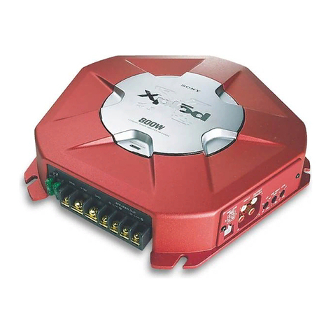
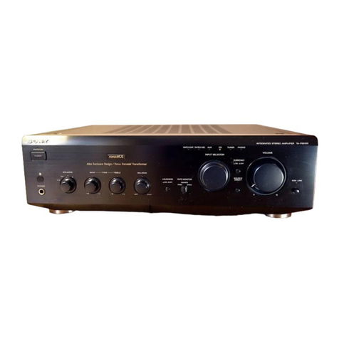
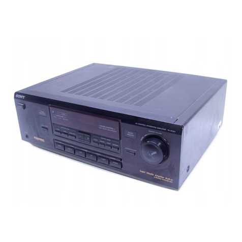
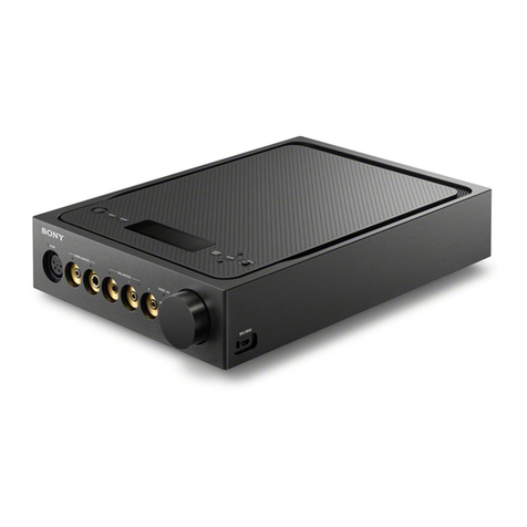
Sony XM-604M - Amplifier User manual

1
SERVICE MANUAL
US Model
Canadian Model
AEP Model
UK Model
E Model
XM-604M
STEREO POWER AMPLIFIER
Circuit system OTL (output transformerless) circuit
Pulse power supply
Inputs RCA pin jacks
High level input connector
Input level adjustment range
0.3 – 6 V (RCA pin jacks),
2.8 – 12 V (High level input)
Outputs Speaker terminals
Speaker impedance 2 – 8 Ω(stereo)
4 – 8 Ω(when used as a bridging amplifier)
Maximum output 4 speakers: 110 W ×4 (at 4 Ω)
3 speakers: 150 W ×2 (at 2 Ω)+ 300 W ×1 (BTL, at 4 Ω)
Rated output (supply voltage at 14.4 V)
4 speakers:
60 W ×4 (20 Hz – 20 kHz, 1% THD+N, at 4 Ω)
70 W ×4 (20 Hz – 20 kHz, 1% THD+N, at 2 Ω)
Frequency response 5 Hz – 50 kHz ( dB)
Harmonic distortion 0.005% or less (at 1 kHz, 4 Ω)
Low-pass filter 80 Hz, –18 dB/oct
High-pass filter 80 Hz, –12 dB/oct
Power requirements 12 V DC marine battery (negative ground)
Power supply voltage 10.5 – 16 V
Current drain at rated output : 33 A (4 Ω, 60 W ×4)
Remote input : 1 mA
Dimensions Approx. 401 ×55 ×264 mm
(15 7/8 ×2 1/4 ×10 1/2 in) (w/h/d)
not incl. projecting parts and controls
Mass Approx. 3.2 kg (7 lb 1 oz) not incl. accessories
Supplied accessories Mounting screws (4)
High level input cord (1)
Protection cap (1)
Design and specifications are subject to change without
notice.
SPECIFICATIONS
+0
–3
Ver. 1.0 2006. 10
9-887-453-01
2006J04-1
© 2006. 10
Sony Corporation
eVehicle Division
Published by Sony Techno Create Corporation
AUDIO POWER SPECIFICATIONS
POWER OUTPUTAND TOTAL HARMONIC DISTORTION
55 watts per channel minimum continuous average power into
4 ohms, both channels driven from 20 Hz to 20 kHz with no more
than 0.04% total harmonic distortion per Car Audio Ad Hoc Committee
standards.

2
TABLE OF CONTENTS
1. GENERAL
Location and Function of Controls.......................................... 3
Connections ............................................................................. 4
2. DISASSEMBLY
2-1. Bottom Plate........................................................................ 6
2-2. Main Board Section ............................................................ 7
2-3. Front Panel .......................................................................... 7
3. DIAGRAMS
3-1. Block Diagram .................................................................... 9
3-2. Printed Wiring Board ........................................................ 10
3-3. Schematic Diagram –Main Section (1/2)– ........................ 11
3-4. Schematic Diagram –Main Section (2/2)– ........................ 12
4. EXPLODED VIEWS
4-1. Heat Sink (Main) Section.................................................. 13
4-2. Main Board Section .......................................................... 14
5. ELECTRICAL PARTS LIST ........................................ 15
XM-604M
PROTECTOR OPERATION CHECK
Thermal Protect
1. Short across TH901 with the power on.
2. Verify that the protector is operated and D918 illuminates red.
3. Verify that the protector is released and D918 illuminates green
when the short is removed.
4. Likewise, perform items 1 to 3 for TH902 and TH903.
Over Current Protect
1. Short between the positive and negative sides of the speaker
output terminals CN903 and CN904 with the power on.
(Perform this shorting for each channel on FRONT and REAR.)
2. Verify that the protector is operated and D918 illuminates red.
3. Verify that the protector is not released and D918 remains red
even when the short is removed.
4. Verify that the protector is released and D918 illuminates green
when the power is turned off and then on again.
Offset Protect
1. Short between the +12V terminal of CN904 and the (L+R) + or
(L+R) – of the speaker output terminal CN904.
(Short between +12V terminal and (L+R) + and between +12V
terminal and (L+R) –.)
2. Verify that the protector is operated and D918 illuminates red.
3. Verify that the protector is not released and D918 remains red
even when the short is removed.
4. Verify that the protector is released and D918 illuminates green
when the power is turned off and then on again.
UNLEADED SOLDER
Boards requiring use of unleaded solder are printed with the lead
free mark (LF) indicating the solder contains no lead.
(Caution: Some printed circuit boards may not come printed with
the lead free mark due to their particular size.)
: LEAD FREE MARK
Unleaded solder has the following characteristics.
• Unleaded solder melts at a temperature about 40°C higher than
ordinary solder.
Ordinary soldering irons can be used but the iron tip has to be
applied to the solder joint for a slightly longer time.
Soldering irons using a temperature regulator should be set to
about 350°C.
Caution: The printed pattern (copper foil) may peel away if the
heated tip is applied for too long, so be careful!
•Strong viscosity
Unleaded solder is more viscous (sticky, less prone to flow)
than ordinary solder so use caution not to let solder bridges
occur such as on IC pins, etc.
•Usable with ordinary solder
It is best to use only unleaded solder but unleaded solder may
also be added to ordinary solder.
Notes on Chip Component Replacement
•Never reuse a disconnected chip component.
•Notice that the minus side of a tantalum capacitor may be
damaged by heat.
SAFETY-RELATED COMPONENT WARNING!!
COMPONENTS IDENTIFIED BY MARK 0OR DOTTED LINE
WITH MARK 0ON THE SCHEMATIC DIAGRAMS AND IN
THE PARTS LIST ARE CRITICAL TO SAFE OPERATION.
REPLACE THESE COMPONENTS WITH SONY PARTS WHOSE
PART NUMBERS APPEAR AS SHOWN IN THIS MANUAL OR
IN SUPPLEMENTS PUBLISHED BY SONY.
ATTENTION AU COMPOSANT AYANT RAPPORT
À LA SÉCURITÉ!!
LES COMPOSANTS IDENTIFIÉS PAR UNE MARQUE 0SUR LES
DIAGRAMMES SCHÉMATIQUES ET LA LISTE DES PIÈCES
SONT CRITIQUES POUR LASÉCURITÉ DE FONCTIONNEMENT.
NE REMPLACER CES COMPOSANTS QUE PAR DES PIÈCES
SONY DONT LES NUMÉROS SONT DONNÉS DANS CE MANUEL
OU DANS LES SUPPLÉMENTS PUBLIÉS PAR SONY.

3
XM-604M
SECTION 1
GENERAL This section is extracted
from instruction manual.
Location and Function of
Controls
1POWER/PROTECTOR indicator
Lights up in green during operation.
When the PROTECTOR is activated the
indicator will change from green to red.
When the PROTECTOR is activated refer to
the Troubleshooting Guide.
2LEVEL adjustment control
The input level can be adjusted with this
control. Turn it in the clockwise direction
when the output level of the marine audio
unit seems low.
3HPF switch
When the HPF switch is set to ON, the
High-
pass filter
(80 Hz) is effective.
4LPF switch
When the LPF switch is set to ON, the
Low-
pass filter
(80 Hz) is effective.
Emplacement et fonction des
commandes
1Indicateur POWER/PROTECTOR
S’allume en vert lors du fonctionnement de
l’appareil.
Lorsque PROTECTOR est activé, l’indicateur
passe du vert au rouge.
Lorsque PROTECTOR est activé, reportez-
vous au Guide de dépannage.
2Commande de réglage LEVEL
Le niveau d’entrée peut se régler avec cette
commande. Tournez cette commande dans le
sens des aiguilles d’une montre lorsque le
niveau de sortie du lecteur audio marin
semble faible.
3Commutateur HPF
Lorsque le commutateur HPF est réglé sur
ON, le filtre passe-haut (80 Hz) est activé.
4Commutateur LPF
Lorsque le commutateur LPF est réglé sur
ON, le filtre passe-bas (80 Hz) est activé.
POWER/
PROTECTO
R
(80Hz)
LPF
LEVEL
REAR
OFF ON
1
2
4
60.3V
0.5
(80Hz)
HPF
LEVEL
FRONT
OFF ON
1
2
4
60.3V
0.5
Precautions
• This unit is designed for negative ground 12 V
DC operation only.
• Use speakers with an impedance of 2 to 8
Ω
(4
to 8
Ω
when used as a bridging amplifier).
• Do not connect any active speakers (with built-
in amplifiers) to the speaker terminals of the
unit. Doing so may damage the active speakers.
• If your boat is moored in direct sunlight and
there is a considerable rise in temperature
inside the boat, allow the unit to cool down
before use.
• When installing the unit horizontally, be sure
not to cover the fins with the floor carpet etc.
• If this unit is placed too close to the marine
audio unit or antenna, interference may occur.
In this case, relocate the amplifier away from
the marine audio unit or antenna.
• If no power is being supplied to the marine
audio unit, check the connections.
• This power amplifier employs a protection
circuit
*
to protect the transistors and speakers if
the amplifier malfunctions. Do not attempt to
test the protection circuits by covering the heat
sink or connecting improper loads.
• Do not use the unit on a weak battery as its
optimum performance depends on a good
power supply.
• For safety reasons, keep your marine audio unit
volume moderate so that you can still hear
sounds outside your boat.
Fuse Replacement
If the fuse blows, check the power connection
and replace both the fuses. If the fuse blows
again after replacement, there may be an internal
malfunction. In such a case, consult your nearest
Sony dealer.
Warning
When replacing the fuse, be sure to use one
matching the amperage stated above the fuse
holder. Never use a fuse with an amperage rating
exceeding the one supplied with the unit as this
could damage the unit.
*
Protection circuit
This amplifier is provided with a protection circuit
that operates in the following cases:
— when the unit is overheated
— when a DC current is generated
— when the speaker terminals are short-circuited.
The color of the POWER/PROTECTOR indicator will
change from green to red, and the unit will shut
down.
If this happens, turn off the connected equipment,
take out the cassette tape or disc, and determine
the cause of the malfunction. If the amplifier has
overheated, wait until the unit cools down before
use.
If you have any questions or problems
concerning your unit that are not covered in this
manual, please consult your nearest Sony dealer.
Précautions
•Cet appareil est conçu pour fonctionner
uniquement sur un courant de 12 V CC avec
masse négative.
•Utilisez des haut-parleurs d’une impédance
appropriée de 2 à 8
Ω
(stéréo), 4 à 8
Ω
(en cas
d’utilisation comme amplificateur en pont).
•Ne raccordez pas de haut-parleurs actifs (avec
amplificateurs intégrés) aux bornes des haut-
parleurs de cet appareil. Cela risquerait en effet
d’endommager les haut-parleurs actifs.
•Lorsque votre bateau est amarré en plein soleil
et que la température a augmenté de façon
considérable, laissez refroidir l’appareil avant
de l’utiliser.
•Si vous installez l’appareil à l’horizontale, ne
recouvrez pas les ailettes de ventilation avec le
tapis de sol ou quoi que ce soit d’autre.
•Si cet appareil est placé trop près du lecteur
audio marin ou de l’antenne, il se peut que des
interférences se produisent. Dans ce cas,
éloignez l’amplificateur du lecteur audio marin
ou de l’antenne.
•Sile lecteur audio marin n’estpas alimenté,
vérifiez les connexions.
•Cet amplificateur de puissance est équipé d’un
circuit de protection
*
conçu pour protéger les
transistors et les haut-parleurs en cas de
défaillance de l’amplificateur. N’essayez pas de
tester l’efficacité des circuits de protection en
recouvrant le dissipateur thermique ou en
effectuant de mauvaises connexions.
•N’utilisez pas l’appareil avec une batterie faible,
car sa performance optimale dépend d’une
bonne alimentation en électricité.
• Pour des raisons de sécurité, maintenez le
volume du lecteur audio marin à un niveau
modéré afin d’entendre les bruits extérieurs.
Remplacement du fusible
Si le fusible fond, vérifiez les connexions de
l’alimentation et remplacez les deux fusibles. Si le
fusible fond de nouveau après avoir été
remplacé, cela peut révéler une défaillance
interne de l’appareil. Dans ce cas, consultez votre
détaillant Sony le plus proche.
Avertissement
Lorsque vous remplacez le fusible, veillez à
utiliser un fusible dont la capacité en ampères
correspond à celle inscrite sur le porte-fusible.
N’utilisez jamais de fusible dont la capacité
dépasse celle du fusible fourni avec l’appareil car
cela pourrait endommager l’appareil.
*
Circuit de protection
Cet amplificateur est fourni avec un circuit de
protection qui entre en fonction dans les cas
suivants :
—lorsque l’appareil est en surchauffe ;
—lorsqu’un courant continu est généré ;
—lorsque les bornes de haut-parleur sont court-
circuitées.
La couleur de l’indicateur POWER/PROTECTOR
passe du vert au rouge et l’appareil se met hors
tension.
Dans ce cas, éteignez les appareils raccordés,
retirez la cassette ou le disque et déterminez
l’origine du problème. Si l’amplificateur est en
surchauffe, attendez qu’il refroidisse avant
d’utiliser l’appareil.
Si vous avez des questions ou des problèmes
concernant votre appareil qui ne sont pas
abordés dans ce mode d’emploi, adressez-vous à
votre détaillant Sony le plus proche.

4
XM-604M
Avertissement
• Avant d’effectuer les raccordements,
débranchez la borne de masse de la batterie de
voiture pour éviter de provoquer un court-
circuit.
• Utilisez des haut-parleurs d’une capacité
adéquate. Si vous utilisez des haut-parleurs de
faible capacité, ils risquent d’être endommagés.
• Les phases de cet amplificateur sont inversées.
• Ne raccordez pas la borne
#
du système de
haut-parleurs à la carrosserie de la voiture, ou
la borne
#
du haut-parleur droit à celle du
haut-parleur gauche.
• Éloignez les cordons d’entrée et de sortie du fil
d’alimentation électrique afin d’éviter que des
interférences ne se produisent.
• Cet appareil est un amplificateur de haute
puissance. Il se peut donc qu’il n’atteigne pas sa
puissance maximale s’il est utilisé avec les
cordons de haut-parleurs de la voiture.
• Si votre voiture est équipée d’un ordinateur de
bord pour la navigation ou autre, ne
débranchez pas le fil de masse de la batterie de
la voiture. Si vous débranchez ce fil, toute la
mémoire de l’ordinateur risque d’être effacée.
Pour éviter tout risque de court-circuit lorsque
vous effectuez les raccordements, branchez le
fil d’alimentation de +12 V uniquement après
avoir branché tous les autres fils.
Power Connection Wires (not supplied)
Câbles d’alimentation (non fournis)
Make the terminal connections as illustrated below.
Effectuez les connexions des bornes comme illustré ci-dessous.
Pass the wires through the cap, connect the wires, then cover the terminals with the cap.
Note
When you tighten the screw, be careful not to apply too much torque
*
as doing so may damage the screw.
*
The torque value should be less than 1 N•m.
Faites passer les fils par le cache, raccordez les fils, puis recouvrez les bornes avec le cache.
Remarque
Lorsque vous vissez la vis, faites attention à ne pas appliquer une trop grande force
*
, car cela pourrait
endommager la vis.
*
Le couple de serrage doit être inférieur à 1 N•m.
to a metal point of the boat
vers un point métallique du
bateau
REM
+
12VGND
REM
+
12V GND
33
c
Cautions
• Before making any connections, disconnect the
ground terminal of the marine battery to avoid
short circuits.
• Be sure to use speakers with an adequate power
rating. If you use small capacity speakers, they
may be damaged.
• This is a Phase-Inverted Amplifier.
• Do not connect the
#
terminal of the speaker
system to the frame of the boat, and do not
connect the
#
terminal of the right speaker
with that of the left speaker.
• Install the input and output cords away from
the power supply wire as running them close
together can generate some interference noise.
• This unit is a high powered amplifier.
Therefore, it may not perform to its full
potential if used with the speaker cords
supplied with the boat.
• If your boat is equipped with a computer
system for navigation or some other purpose,
do not remove the ground wire from the
marine battery. If you disconnect the wire, the
computer memory may be erased. To avoid
short circuits when making connections,
disconnect the +12 V power supply wire until
all the other wires have been connected.
Fuse (50 A)
Fusible (50 A) +12 V marine battery
Batterie de bateau +12 V
Marine audio unit
Lecteur audio marin
Remote output
*
1
Sortie de télécommande
*
1
(REM)
less than 450 mm (18 in)
moins de 450 mm (18 po)
Remarques sur l’alimentation électrique
• Raccordez le câble d’alimentation +12 V
uniquement après avoir réalisé toutes les autres
connexions.
•Raccordez solidement le fil de masse de l’appareil
à
un point métallique du bateau. Une connexion
lâche risque de provoquer un problème de
fonctionnement de l’amplificateur.
• Veillez à raccorder le fil de commande à distance du
lecteur audio marin à la borne de commande à
distance.
• Si vous utilisez un lecteur audio marin dont
l’amplificateur ne comporte pas de sortie de
commande à distance, raccordez la borne d’entrée
de commande à distance (REMOTE) à la prise
d’alimentation accessoires.
• Utilisez un câble d’alimentation doté d’un fusible
(50 A).
• Tous les fils électriques raccordés à la borne positive
de la batterie doivent être protégés par un fusible à
une distance maximum de 450 mm (18 po) à la
borne de la batterie et avant de passer dans une
partie métallique quelconque.
• Assurez-vous que les fils de la batterie du bateau
raccordés à ce dernier (sol au châssis)
*
2
sont d’un
calibre au moins égal à celui du fil électrique
principal reliant la batterie et l’amplificateur.
• Pendant une utilisation à pleine puissance, un
courant d’une intensité supérieure à 50 A circule
dans le système. Assurez-vous que les câbles à
raccorder aux bornes +12 V et GND de cet appareil
sont de calibre supérieur à 10 (AWG-10) ou d’une
section supérieure à 5 mm
2
(
7
/
32
po
2
).
Notes on the power supply
•Connect the +12 V power supply wire only after all
the other wires have been connected.
•Be sure to connect the ground wire of the unit
securely to a metal point of the boat. A loose
connection may cause a malfunction of the
amplifier.
• Be sure to connect the remote control wire of the
marine audio unit to the remote terminal.
•When using a marine audio unit without a remote
output on the amplifier, connect the remote input
terminal (REMOTE) to the accessory power supply.
•Use a power supply wire with a fuse attached (50 A).
• All power wires connected to the positive battery
post should be fused within 450 mm (18 in) of the
battery post, and before they pass through any
metal.
•Make sure that the boat’s battery wires connected
to the boat (ground to frame)
*
2
are of a wire gauge
at least equal to that of the main power wire
connected from the battery to the amplifier.
•During full-power operation, a current of more
than 50 A will run through the system. Therefore,
make sure that the wires to be connected to the
+12 V and GND terminals of this unit are at least
10-Gauge (AWG-10) or have a sectional area of
more than 5 mm
2
(
7
/
32
in
2
).
*
2
Installation
1
Installation
Mount the unit as illustrated.
Montez l’appareil comme illustré.
Before Installation
• Mount the unit either inside a boatwall or the
cabin.
• Choose the installation location carefully so that
the unit will not interfere with normal sailing
operations.
• Do not install the unit under the floor carpet,
where the heat dissipation from the unit will be
considerably impaired.
• Avoid installing the unit in areas subject to:
— high temperatures such as from direct
sunlight or hot air from the heater
— rain, sea water or moisture
—dust or dirt.
• This unit is not waterproof. Install the unit
where sea or rain water cannot enter the unit. If
you install the unit in such a place, ensure that
it is adequately waterproofed.
First, place the unit where you plan to install it,
and mark the positions of the 4 screw holes on
the mounting board (not supplied). Then drill a 3
mm (
1
/
8
in) pilot hole at each mark and mount
the unit onto the board with the supplied
mounting screws. The mounting screws are all
15 mm (
19
/
32
in) long, so make sure that the
mounting board is thicker than 15 mm (
19
/
32
in).
Before drilling and making holes, make sure that
the mounting holes will not damage the fuel
tank, fuel lines, electrical wiring, or body of the
boat.
Avant l’installation
• Montez l’appareil à l’intérieur de la paroi mur
du bateau ou dans la cabine.
• Choisissez soigneusement l’emplacement
d’installation afin que l’appareil ne gêne pas la
navigation.
• N’installez pas l’appareil sous le tapis de sol car
la dissipation thermique ne pourrait pas se faire
correctement.
• N’installez pas l’appareil dans des endroits
soumis :
—àdes températures élevées, comme en plein
soleil ou près du chauffage ;
—àla pluie, à l’eau de mer ou à l’humidité ;
—àla poussière ou à la saleté.
• Cet appareil n’est pas étanche. Installez
l’appareil dans un endroit protégé contre l’eau
de mer et l’eau de pluie. Si vous installez
l’appareil dans un endroit susceptible d’être
exposé à l’eau, vérifi ez qu’il est bien protégé.
Posez d’abord l’appareil à l’endroit où vous
souhaitez l’installer et tracez un repère de
positionnement pour les 4 orifices de vis sur la
plaque de montage (non fournie). Percez des
orifices de 3 mm (
1
/
8
po) au niveau de chaque
repère et fixez l’appareil sur la plaque avec les vis
de montage fournies. La longueur des vis de
montage est de 15 mm (
19
/
32
po). Assurez-vous
donc que l’épaisseur de la plaque de montage est
supérieure à 15 mm (
19
/
32
po).
Avant de percer les trous de montage de
l’appareil, assurez-vous que ces derniers
n’endommageront pas le réservoir de carburant,
les tuyaux d’alimentation en carburant, le
câblage électrique ou la coque du bateau.
*
1
If you have the factory original or some other marine audio unit without a remote output for the
amplifier, connect the remote input terminal (REMOTE) to the accessory power supply.
In High level input connection, marine audio unit can also be activated without need for REMOTE
connection. However, this function is not guaranteed for all marine audio units.
*
1
Si vous disposez du lecteur audio marin d’origine ou d’un autre lecteur audio marin dont l’amplificateur
ne comporte pas de sortie de télécommande à distance, raccordez la borne d’entrée de commande à
distance (REMOTE) à la prise d’alimentation accessoires.
Dans une connexion d’entrée à haut niveau, le lecteur audio marin peut également être activé sans
raccordement à REMOTE. Toutefois, cette fonction n’est pas garantie pour tous les lecteurs audio marins.
Connections

5
XM-604M
High Level Input Connection
Connexion d’entrée à haut niveau
Line Input Connection
Connexion d’entrée de ligne
BB
BB
B
AA
AA
A
Input Connections/Connexions d’entrée
4-Speaker System
Système à 4 haut-parleurs
11
11
1
3-Speaker System
Système à 3 haut-parleurs
22
22
2
2-Way System
Système 2 voies
33
33
3
Speaker Connections
Turn on or off the LPF and HPF switch at the unit rear as illustrated below.
Conexións des haut-parleurs
Réglez le commutateur LPF et HPF situé à l’arrière de l’appareil à On ou Off, comme indiqué dans
l’illustration ci-dessous.
Rear
Arrière
Front
Avant
Front right speaker output
Sortie du haut-parleur avant droit Rear right speaker output
Sortie du haut-parleur arrière droit
White
Blanc
Gray
Gris
2
Green
vert
Purple
Mauve
Front left speaker output
Sortie du haut-parleur avant gauche Rear left speaker output
Sortie du haut-parleur arrière gauche
LINE OUTLINE OUT
Striped
Rayé
Striped
Rayé Striped
Rayé
Striped
Rayé
(80Hz)
OFF ON
LPF
(80Hz)
OFF ON
HPF
(80Hz)
OFF ON
LPF
(80Hz)
OFF ON
HPF
RL
Notes
•In this system, the volume of the subwoofer will be controlled by the marine audio unit fader control.
•In this system, the output signals to the subwoofer will be the combination of both the REAR L and R
INPUT jacks or the REAR high level input connector signals.
Remarques
•Dans ce système, le volume du caisson de graves est contrôlé par la commande de balance avant/arrière
du lecteur audio marin.
•Dans ce système, les signaux émis vers le caisson de graves sont constitués des signaux des prises
REAR L et R INPUT ou des signaux du connecteur d’entrée de haut niveau REAR.
Front speaker (min. 2 Ω)
Haut-parleurs avant (min. 2 Ω)
Rear speaker (min. 2 Ω)
Haut-parleurs arrière (min. 2 Ω)
Left
gauche Right
droit
Subwoofer (min. 4 Ω)
Caisson de graves (min. 4 Ω)
Full range speakers (min. 2 Ω)
Hauts-parleurs pleine gamme (min. 2 Ω)
(80Hz)
OFF ON
LPF
(80Hz)
OFF ON
HPF
Subwoofer (min. 2 Ω)
Caisson de graves (min. 2 Ω)
Full range speakers (min. 2 Ω)
Hauts-parleurs pleine gamme (min. 2 Ω)
Note
In this system, the volume of the subwoofer will be controlled by the marine audio unit fader control.
Remarque
Dans ce système, le volume du caisson de graves est contrôlé par la commande de balance avant/arrière du
lecteur audio marin.
Left
gauche Right
droit
Left
gauche Right
droit
Left
gauche Right
droit
Left
gauche Right
droit
LR LR
FRONT REAR
High Level Input Connector
Connecteur d’entrée à haut niveau
Gray
Gris
White
Blanc
Striped/White
Rayé blanc
Striped/Gray
Rayé gris
Green
Vert
Purple
Mauve
Striped/Purple
Rayé mauve
Striped/Green
Rayé vert
Marine audio unit
Lecteur audio marin
Marine audio unit
Lecteur audio marin

6
XM-604M SECTION 2
DISASSEMBLY
Note : This set can be disassemble according to the following sequence.
Note : Follow the disassembly procedure in the numerical order given.
2-1. BOTTOM PLATE
2-1. BOTTOM PLATE
(Page 6)
2-2. MAIN BOARD SECTION
(Page 7)
SET
2-3. FRONT PANEL
(Page 7)
1
three
screws
(+BTP 3
×
6)
3
bottom plat
e
2
four
screws
(+BTP 3
×
6)

7
XM-604M
2-2. MAIN BOARD SECTION
2-3. FRONT PANEL
1
three
screw
s
(+P 3
×
8)
2
three
screws
(+P 3
×
8)
3
three
screws
(+P 3
×
8)
4
screw
(+BTP 3
×
6)
5
MAIN board section
heat sink (main)
1
three
screws
(+P 3
×
8)
2
screw
(+P 3
×
8)
3
screw
(+P 3
×
8)
4
front
panel
5
MAIN board

8
XM-604M
NOTE FOR REPLACEMENT OF THE
TRANSISTORS:
The transistors Q110, 111, 210, 211, 310, 311, 410 and 411 have
two different ranks: P rank andY rank.
The rank of these transistors need to be selected properly according
to each channel.When replacing any one of these transistors, check
its rank and replace with the appropriate transistor of the same rank.
Rank Q110, 210, 310, 410 Q111, 211, 311, 411
P2SC5100-P 2SA1908-P
(8-729-024-79) (8-872-024-76)
Y2SC5100-Y 2SA1908-Y
(8-729-024-80) (8-872-024-77)
DISCRIMINATION:
A1908: 2SA1908
C5100: 2SC510
0
P: RANK P
Y: RANKY
THIS NOTE IS COMMON FOR PRINTED WIRING
BOARDS AND SCHEMATIC DIAGRAMS.
(In addition to this, the necessary note is
printed in each block.)
for schematic diagram:
•All capacitors are in µF unless otherwise noted. (p: pF)
50 WV or less are not indicated except for electrolytics
and tantalums.
•All resistors are in Ωand 1/4W or less unless otherwise
specified.
•A: B+ Line.
•B: B– Line.
•Powervoltage isdc 14.4Vand fedwithregulateddcpower
supply from +12V and REM terminals.
•Voltage is dc with respect to ground under no-signal
condition.
•Voltagesaretaken withaVOM (Inputimpedance 10MΩ).
Voltage variations may be noted due to normal produc-
tion tolerances.
•Waveforms are taken with a oscilloscope.
Voltage variations may be noted due to normal produc-
tion tolerances.
•Circled numbers refer to waveforms.
•Signal path.
F: AUDIO
for printed wiring boards:
•X: parts extracted from the component side.
•: Pattern from the side which enables seeing.
Note:
The components identi-
fied by mark 0or dotted
linewith mark0are criti-
cal for safety.
Replace only with part
number specified.
Note:
Lescomposants identifiés par
une marque 0sont critiques
pour la sécurité.
Ne les remplacer que par une
piéce portant le numéro
spécifié.
SECTION 3
DIAGRAMS
CThese are omitted
BE

99
XM-604M
XM-604M
3-1. BLOCK DIAGRAM
3
2
1
PRE AMP
IC801 (1/2)
1
GAIN CONTROL AMP
IC805 (1/2)
HPF
IC803 (1/2) DIFFERENTIAL
AMP
Q103
POWER
AMP
Q110
DRIVE
AMP
Q104
DIFFERENTIAL
AMP
Q102
POWER
AMP
Q111
DRIVE
AMP
Q105
BIAS
Q106,107
BIAS
Q206,207
CN902 (1/2)
CN901
MUTE
SWITCH
Q101
+12V
GND
9
PRE AMP
IC801 (2/2)
DIFFERENTIAL
AMP
Q203
POWER
AMP
Q210
DRIVE
AMP
Q204
DIFFERENTIAL
AMP
Q202
MUTE
CONTROL
Q802
POWER
AMP
Q211
DRIVE
AMP
Q205
-3
-2
-4
FL
FR
RL
RR
-1
L
FRONT
INPUT
D906
D907
REAR
R
CN903
L
R
MUTE
SWITCH
Q201
1
2
14
12
REF.
REG
CN904(2/2) F901
25A
SWITCHING
DRIVER
Q910,911
SWITCHING
DRIVER
Q912,913
DRIVER
Q908,909
8
10
11
3
D918
POWER/
PROTECTOR
FRONT
SPEAKER
OUT
DC-DC
CONVERTER
TRANSFORMER
T901
DC-DC CONVERTER
IC903
B+
SWITCH
Q905
OVERLOAD
DET
Q112
OVERLOAD
DET
Q212
CN904(1/2)
L
(L+R)
R
REAR
SPEAKER
OUT
6
5
CN902 (2/2)
L
(L+R)
R
(L+R)
REM
+15V REG
Q807
–15V REG
Q808
PROTECTOR
DETECT
Q901,902
OVERLOAD
PROTECT
(REAR)
Q805,806
OVERLOAD
PROTECT
(FRONT)
Q803,804
POWER
ON/OFF
Q906
DC DET
IC902
+30V
+15V
–30V
–15V
D804
RECT
D803
RECT
(FRONT)
(REAR)
HIGH
LEVEL
INPUT/
SENSING
POWER ON
F902
25A
PRE AMP
IC802 (1/2)
1
LPF
IC804 (1/2)
GAIN CONTROL AMP
IC806 (1/2)
DIFFERENTIAL
AMP
Q303
POWER
AMP
Q310
DRIVE
AMP
Q304
DIFFERENTIAL
AMP
Q302
POWER
AMP
Q311
DRIVE
AMP
Q305
MUTE
SWITCH
Q301
PRE AMP
IC802 (2/2)
37
LPF
IC804 (2/2)
DIFFERENTIAL
AMP
Q403
POWER
AMP
Q410
DRIVE
AMP
Q404
DIFFERENTIAL
AMP
Q402
POWER
AMP
Q411
DRIVE
AMP
Q108
DRIVE
AMP
Q109
DRIVE
AMP
Q208
DRIVE
AMP
Q209
DRIVE
AMP
Q308
DRIVE
AMP
Q309
DRIVE
AMP
Q408
DRIVE
AMP
Q409
DRIVE
AMP
Q405
MUTE
SWITCH
Q401
OVERLOAD
DET
Q412
6
OVERLOAD
DET
Q312
3
2
5
TEMP.DET
TH901-903
LED DRIVER
Q903
R
(PROTECTOR)
G
(POWER)
THERMAL DET
Q914,915
VCC
REF
D905 D901
D902
OVER
VOLTAGE
DETECT
Q907
2
HPF 3
2
7
7
GAIN CONTROL AMP
IC805 (2/2)
HPF
IC803 (2/2)
6
HPF
LPF
5
6
LPF
2
3
6 7
GAIN CONTROL AMP
IC806 (2/2)
2 1
6
5
MUTE
CONTROL
Q810
MUTE
CONTROL
Q809
MUTE
CONTROL
Q811
MUTE
CONTROL
Q812
15
16
1
7
1
7
BIAS
Q306,307
BIAS
Q406,407
VR801-1
VR801-2
VR802-1
VR802-2
S801-1
S801-2
VR801
LEVEL
(FRONT)
ON
OFF
VR802
LEVEL
(REAR)
S801
HPF
(80Hz)
(FRONT)
OFF ON
S802
S802-1
S802-2
LPF
(80Hz)
(REAR)
• Signal path
: AUDIO

10 10
XM-604M
XM-604M
3-2. PRINTED WIRING BOARD : Uses unleaded solder.
1
A
B
C
D
E
F
G
H
I
J
2345678910111213
-1 -7
-2 -8
FL RLFR RR
L R
POWER/
PROTECTOR
D918
MAIN BOARD
B
C
E
B
C
E
B
C
E
B
C
E
OFF ON
S801
HPF(80Hz)
VR801
LEVEL
-2
-1
-1
-2
LR
FRONT SPEAKER OUT
(L+R)
INPUT
FRONT REAR
-1
L-3
L
-2
R-4
RHIGH LEVEL INPUT/
SENSING POWER ON
OFF ON
S802
LPF(80Hz)
VR802
LEVEL
REAR SPEAKER OUT
(L+R)
1-871-258- 11
25A25A
REM +12V GND
S
D
G
S
D
G
S
D
G
S
D
G
K
A
K
A
K
A
ECB ECB ECB ECB
-2
-1
-1
-2
C801 C803
C805
R943
R172
TP15
TP14
TP13 R272
Q803
R812
C811
R171
R271
Q804
TP16
R168
R163
R165
Q107
R164
R167
R177
R178
R170
Q112
R268
R263
R265
Q207
R264
R267
TP17
TP18
TH903
R277
R278
Q212
R270
TP903
D901
R907
TP902
R908
TH902
TP19
JC731
R368
R365
R363
R266
R166
C152
C252
R466
JC729
C352
R259
R258
R257
R260
R159
R158
R157
R160
R155
R156
R176 R175 R276 R275
R255
R256
R360 R357
R358
R359 R460
R457 R458
R459
C452
JC728
Q402
R455
Q303
Q203
Q202
Q103
Q102
C153
R161
R254 C253
R261
R253
Q812
R355
R376 R375
R356
C353
R361
R462
R454
R818
R452
R451
R817
JC717
JC718
JC719
JC720
R351 R354
Q401
Q301
R353
R362
Q811
R352
JC723
JC724
Q802
R809
Q810
R807
D801
R808
Q809
R262
R816
JC725
C809
C808
R109
R806
Q201
R251
R151
R252
Q101
R152
R162
R153
R154
IC805
C112 JC726
C108
R108
D802
Q302
C109
IC803
R209 R208
C208
C209
R106
R102
R104
C105 C107
R105
R107
R103
C116
C117
R304
R302 C305C307
R303
R305
R307
C406
R406
C407
R407
C306
R308
R408
JC722
JC721
C316
C317
R409
C410
R411
R410
R311
R310
R309
C310
R401
C402
C918
TP10
R405
R403
R404
R402
R101R201
C216
C804
C101
R944
R803
R801
R802
TP11
JC727
R211
R111
R212
R112
R110
R210
JC732 R213
R113
C212
TP12
R810
R202
C217
R204
R203
R205
R207
C207
C205
R206
C206
IC801
C106
R306
IC802
C405
D906
R804
C102
C201
C202
C401
C301
D907
R945
R946
R805
C417
C416
R929
R930
R932
R933
C915
Q908
D805
D806
C824
C825
R814
C917
TP28
JC702
R903
IC903
C902
Q901
Q902
C901
Q909
R922
R924
R925
R926
R927
R923
R920
R921
TH901
R815
R901
R902
TP29
JC703
JC704
JC714
C916
JC701
R931
Q307
R364
R370
R367
R377
Q312
R378
R468
R463
R465
Q407
R464
R470
R467
R477
R478
Q412
TP20 TP22
TP23
TP24
TP25
C818
C817
D807
C823
TP21
TP27
TP26
R313
R475
Q403
R476
R456
R453
C453
R461
IC804
JC716
IC806
C412
C312
R412
R312
R413
R904
R905
Q903
JC715 R372 TP7
TP8
R928
R371
R471
C812
R811
R813
R910
R911
C904
C907
Q805
R912
R909
D902
C903
R939
R938
R937
R941
R936
D905
Q914
R940
R914
Q915
R915
Q806
JC706
JC707
JC708
JC709
JC710
JC711
JC712
JC713
Q906
C919
R935
R916
TP30 TP901
R919
C909
F902
F901
R472
R942
TP6
Q907
JC705
R917
R918
D904
TP4
TP5
TP9
TP1
TP2
TP3
R934
C911
JC730
R366
C309
C409
C302
R301
D101
D102
D202
D302
D301
D402
D401
D201
C351
C810
JW97
JW96
JW95
CNJ101
JW101
JW102
JW103
JW106
JW105
C815
C408
JW86
JW85
C355 C455
JW38
JW37
JW36
JW35
JW84
JW83
VR802
C411
JW34
CN904
JW33
JW32
JW31
JW4
JW3
JW2
JW1
JW6
JW7
JW8
JW28
JW29
JW30
C913
Q911
JW9
Q910
JW10
Q905
C908
C920
Q912
JW11
JW12
Q913
JW27
JW26
C914
C912
D803
T901
JW20
JW22
C827
JW48
JW47
JW49
JW50
JW51
JW52
R469
JW54
JW55
JW56
JW57
JW59
JW60
JW61
JW62
JW63
JW64
JW65
JW23
C905
JW24
JW25
C906
JW39
JW40
JW41
JW42
JW44
JW43
JW45
JW46
JW74
JW75
C814
JW73
IC902
C308
JW108
JW107
JW104
JW130
R369
JW58
JW129
JW127
JW126
JW124
JW68
Q408
C454
Q404
JW69
Q405
JW70
JW71
Q305
JW72
Q304
C354
Q308
Q409
JW67
JW115
Q309
JW66
Q208
C254
Q204
Q205
JW112
JW114
Q209
JW118
JW119
JW121
JW117
JW122
JW116
JW123
JW125
JW128
JW131
JW135 JW134
JW136
JW17
JW18
L801
JW16
JW15
JW14
D804
JW13
C820
C822 C821
C819
Q206
Q210
JW139
JW140
JW141
JW120
Q109
Q105
JW113
Q104
C154
Q108
JW111
JW142
JW144
JW143
JW145 JW138
Q211
R269
Q110
Q106
Q111
R169
JW147
JW148
JW149
JW150
JW153
JW152
JW151
C151
JW110
JW154
C251
JW109
C211
C111
C110
JW157
JW159
C210 JW158
S801
JW161
JW162
C155
C255
CN903
CN901
JW90
S802
JW89
JW88
JW87
D918
C910
L901
JW5
JW91
JW93
JW92
JW94
C802
JW100
JW99
JW98
VR801
JW156
JW155
JW146
JW137
Q306
Q311
JW133
Q310
JW53
Q411 Q410
Q406
JW19
JW21
Q807
C826
Q808
JW160
JW76
JW78
JW79
JW77
C451
JW80
JW81
JW82
C311
JW163
C813
JW164
JW132
Ref. No. Location
D101 E-4
D102 E-4
D201 E-5
D202 E-5
D301 F-6
D302 F-6
D401 F-7
D402 F-7
D801 G-5
D802 G-5
D803 B-13
D804 C-13
D805 D-9
D806 D-10
D807 B-12
D901 B-4
D902 F-9
D904 G-10
D905 G-9
D906 I-6
D907 I-7
D918 I-8
IC801 H-5
IC802 H-6
IC803 G-4
IC804 G-7
IC805 G-3
IC806 G-8
IC902 F-8
IC903 E-10
Q101 F-4
Q102 F-4
Q103 F-4
Q104 E-4
Q105 E-4
Q106 E-2
Q107 E-2
Q108 E-4
Q109 E-4
Q110 E-1
Q111 F-1
Q112 D-2
Q201 F-4
Q202 F-5
Q203 F-5
Q204 E-5
Q205 E-5
Q206 C-2
Q207 C-2
Q208 E-5
Q209 E-5
• Semiconductor Location
Q210 C-1
Q211 D-1
Q212 B-2
Q301 F-6
Q302 F-6
Q303 F-6
Q304 E-6
Q305 E-6
Q306 B-6
Q307 B-7
Q308 E-6
Q309 E-6
Q310 A-7
Q311 A-5
Q312 C-7
Q401 G-6
Q402 F-7
Q403 F-7
Q404 E-7
Q405 E-7
Q406 B-8
Q407 B-9
Q408 E-7
Q409 E-7
Q410 A-9
Q411 A-8
Q412 B-9
Q802 G-5
Q803 H-3
Q804 H-3
Q805 F-8
Q806 F-9
Q807 D-10
Q808 D-10
Q809 F-5
Q810 F-5
Q811 F-6
Q812 F-6
Q901 E-9
Q902 E-10
Q903 I-8
Q905 G-10
Q906 G-10
Q907 H-10
Q908 E-12
Q909 E-11
Q910 E-13
Q911 F-13
Q912 E-13
Q913 D-13
Q914 G-10
Q915 G-10
Ref. No. Location

11 11
XM-604M
XM-604M
3-3. SCHEMATIC DIAGRAM — MAIN SECTION (1/2) —
(Page 12)
R202
R402
R802
C801R801
R803 C803
R804 C804
R102
R103
R101
C201
C202
R201
R301
R401
C108 C109
C111
C110
R203
C205
C206
C207
C208
C210
C211
C112 R151
R251
R302
R303
R403
C301
C302
C401
C402
C305
C306
C307
C808
C407
C405
C815
C809
C308
C408
C311
C312
C411
R351
R451
C412
R153 R161
R159
R162
C154
R160
R166
R167
R169
R168
R259
R253 R261
R262
R260
C254
R267
R269
R268
R353 R361
R362
R360
R359
C354
R366
R367
R369
R368
R453
R459
R461
R462
R460
C454
R466
R467
R468
R469
R172
R272
R372
R472
C106
C105
C107
C209
C406
R266
C212
VR801
VR801
VR802
VR802
R104 R105 R806
R816
R817
R818
C116
C117
C216 C217
C417
C416
C317 C316
R205 R204
R305 R304
C802
R404 R405
Q201
Q101
Q301
Q401
C101
C102
C151
C251
C351
C451
CN901
CN902
CN903
R106 R107
R207
R206
R208
R212
R112
R308 R311
R307
R306
R312
R412
R411R408
R407
R406
R163
R177
R263
R363
R463
R277
R477
R377
R108
CNJ101
CNJ101
IC801(1/2)
IC801(2/2)
IC803(2/2)
IC803(1/2)
IC805(1/2)
IC805(2/2)
S801
R113
R213
R252
R152
JC727
JC732
JC726
TP10
JC722 JC721
D906
D907
IC802(1/2) C309
IC804(1/2)
IC806(1/2)
IC806(2/2)
IC804(2/2)
IC802(2/2)
JC716
S802
R313 JC719
JC724
JC720
JC715
R352
R452
JC717
JC723
JC718
R413
C310
C410
C409
TP15
TP14
TP13
TP12
TP09
TP08
TP07
TP06
C455
C355
C255
C155
Q102
Q202
Q302
Q402
Q403
Q303
Q203
Q103
Q104
Q204
Q304
Q404
Q405
Q305
Q205
Q105
Q107
Q207
Q307
Q407
Q409
Q309
Q209
Q109
Q108
Q208
Q308
Q408
Q411
Q311
Q211
Q111
Q110
Q210
Q310
Q410 Q412
Q312
Q212
Q112
C152
C153
R154
R165
C252
C253
R265
R254
C352
C353
R365
R354
C452 R465
C453
R454
JC728
JC730
JC729
JC731
R109
R209
R111
R211
R110
R210
R309 R310
R409 R410
R944
R946
R945
R943
R155 R158 R175
R156
R157 R176
R164 Q106 R178
R170
R171
R255 R258 R275
R257 R276
R256
R264 Q206 R278
R270
R271
R355 R358 R375
R357 R376
R356
R364 Q306 R378
R370
R371
R455 R458 R475
R457 R476
R456
R464 Q406 R478
R470
D101
D102
D201
D202
D301
D302
D401
D402
CN904
R471

12 12
XM-604M
XM-604M
• IC Block Diagram
IC903 TL594INSR (MAIN BOARD (2/2))
OSC
REF 5V
ERROR
ERROR
0.1V
Q1
Q2
16 15 14 13 12 11 10 9
1 2 3 4 5 6 7 8
NON
INV
VREF
VCC
C2
E1
E2
OUT
+IN
-IN
COMPEN
CT
RT
C1
GND
TIME
3-4. SCHEMATIC DIAGRAM — MAIN SECTION (2/2) —
(Page 11)
• Waveform
1 V/DIV, 10
µ
sec/DIV
1IC903 5
3.3 Vp-p
18
µ
sec
IC B/D
F901
R912
F902
R919
C909
R934 C911
R809
C904
C906
C907
C903
C901
R903
R902
R901
C917
R805 C805
R928
R931
R920
R921
R929
R930 C913
C914
C817
C818
C819
C821
C820
C822 C823
R814
R815
C824
C825
C826
C827
C811 C813
C814
C915
C916
R932
R933
R914
C918
L901
R940
C908
C902 C812 R813
R812
R807
C810
T901
TH903
TH902
TH901
L801
IC902
R941
R909
Q812 Q811 Q809 Q810
Q802
D801
JC725
JC701
R926
R927
Q908
Q909
Q910
Q912
Q911
Q913
Q807
Q808
D805
D806
D803
D804
JC714
TP26
TP27
TP22
TP23
TP24
TP25
TP29
TP28
JC710
JC712
JC708 JC707
JC709 JC704
JC703 JC702
JC713
JC711
JC705
TP05
TP01
TP04 TP903
TP902
TP901
TP30
Q905
Q907
Q906 D905
Q915
Q914
D901
IC903 Q902
Q901
D807
Q803
Q804
Q805
Q806
R908
R907
C919
R939
C910
TP19
D902
D904
Q903
D802
R808
R923
R922
R924
R925
C912
CN904
R917
R918
R942
R915
R916
C920
R937
R938
R936
R935
R910 C905
R911
R904
R905
D918
R810
R811
JC706

13
XM-604M
SECTION 4
EXPLODED VIEWS
NOTE:
•The mechanical parts with no reference
number in the exploded views are not supplied.
•Items marked “*” are not stocked since
they are seldom required for routine service.
Some delay should be anticipated
when ordering these items.
•Color Indication of Appearance Parts
Example :
KNOB, BALANCE (WHITE) ... (RED)
Parts Color Cabinet’s Color
•Accessories are given in the last of this parts list.
Ref. No. Part No. Description Remark
4-1. HEAT SINK (MAIN) SECTION
R
Ref. No. Part No. Description Remark
R
12-695-958-11 PLATE (TOP), ORNAMENTAL
22-695-959-11 PLATE (SIDE), ORNAMENTAL
32-894-279-01 SCREW (+P 3X8)
42-894-280-01 SCREW (+BTP 3X6)
0F901 1-576-256-11 FUSE (BLADE TYPE) (AUTO FUSE) (25A)
0F902 1-576-256-11 FUSE (BLADE TYPE) (AUTO FUSE) (25A)
#1 7-685-146-19 SCREW +P 3X8 TYPE2 NON-SLIT
#2 7-685-545-19 SCREW +BTP 3X6 TYPE2 N-S
F901
F902
not supplied
not supplied
#2
#1
#1
#1
#2
1
2
3
4
4
The components identified by
mark 0or dotted line with mark
0are critical for safety.
Replace only with part number
specified.
Les composants identifiés par une
marque 0sont critiques pour
la sécurité.
Ne les remplacer que par une piéce
portant le numéro spécifié.

14
XM-604M
4-2. MAIN BOARD SECTION
Ref. No. Part No. Description RemarkRef. No. Part No. Description Remark
51 A-1219-711-A MAIN BOARD, COMPLETE
52 3-225-184-12 SCREW (+PS.TT.3XL)
53 2-693-613-11 PANEL, FRONT
54 3-912-431-01 SCREW (+–P)
55 2-894-279-01 SCREW (+P 3X8)
D803 8-719-079-00 DIODE FCH10A15
D804 8-719-079-01 DIODE FRH10A15
Q110 8-729-024-79 TRANSISTOR 2SC5100-P
Q110 8-729-024-80 TRANSISTOR 2SC5100-Y
Q111 8-729-024-76 TRANSISTOR 2SA1908-P
Q111 8-729-024-77 TRANSISTOR 2SA1908-Y
Q210 8-729-024-79 TRANSISTOR 2SC5100-P
Q210 8-729-024-80 TRANSISTOR 2SC5100-Y
Q211 8-729-024-76 TRANSISTOR 2SA1908-P
Q211 8-729-024-77 TRANSISTOR 2SA1908-Y
Q310 8-729-024-79 TRANSISTOR 2SC5100-P
Q310 8-729-024-80 TRANSISTOR 2SC5100-Y
Q311 8-729-024-76 TRANSISTOR 2SA1908-P
Q311 8-729-024-77 TRANSISTOR 2SA1908-Y
Q410 8-729-024-79 TRANSISTOR 2SC5100-P
Q410 8-729-024-80 TRANSISTOR 2SC5100-Y
Q411 8-729-024-76 TRANSISTOR 2SA1908-P
Q411 8-729-024-77 TRANSISTOR 2SA1908-Y
Q910 6-550-341-01 FET FKV550N
Q911 6-550-341-01 FET FKV550N
Q912 6-550-341-01 FET FKV550N
Q913 6-550-341-01 FET FKV550N
#1 7-685-146-19 SCREW +P 3X8 TYPE2 NON-SLIT
#1
51
52
52
52
52
52
53
54
54
54
52
52
not supplied
not supplied
Q911,Q910,Q912,Q913
Q111,Q110,
Q211,Q210 Q311,Q310,Q411,Q410
D804,D803
not supplied
55
55
Refer to page 8 for Note for
Replacement of the Transistors.

15
XM-604M
SECTION 5
ELECTRICAL PARTS LIST
Ref. No. Part No. Description Remark Ref. No. Part No. Description Remark
NOTE:
•Due to standardization, replacements in
the parts list may be different from the
parts specified in the diagrams or the
components used on the set.
•RESISTORS
All resistors are in ohms.
METAL:Metal-film resistor.
METAL OXIDE: Metal oxide-film resistor.
F:nonflammable
•Items marked “*” are not stocked since
they are seldom required for routine service.
Some delay should be anticipated
when ordering these items.
•SEMICONDUCTORS
In each case, u : µ, for example:
uA.. : µA.. uPA.. : µPA..
uPB.. : µPB.. uPC.. : µPC.. uPD.. : µPD..
•CAPACITORS
uF : µF
•COILS
uH : µH
A-1219-711-A MAIN BOARD, COMPLETE
*********************
3-225-184-12 SCREW (+PS.TT.3XL)
3-912-431-01 SCREW (+–P)
7-685-146-19 SCREW +P 3X8 TYPE2 NON-SLIT
< CAPACITOR >
C101 1-162-927-11 CERAMIC CHIP 100PF 5% 50V
C102 1-162-927-11 CERAMIC CHIP 100PF 5% 50V
C105 1-162-923-11 CERAMIC CHIP 47PF 5% 50V
C106 1-162-927-11 CERAMIC CHIP 100PF 5% 50V
C107 1-162-927-11 CERAMIC CHIP 100PF 5% 50V
C108 1-107-826-11 CERAMIC CHIP 0.1uF 10% 16V
C109 1-107-826-11 CERAMIC CHIP 0.1uF 10% 16V
C110 1-126-933-11 ELECT 100uF 20% 16V
C111 1-126-963-11 ELECT 4.7uF 20% 50V
C112 1-162-927-11 CERAMIC CHIP 100PF 5% 50V
C116 1-107-826-11 CERAMIC CHIP 0.1uF 10% 16V
C117 1-107-826-11 CERAMIC CHIP 0.1uF 10% 16V
C151 1-126-947-11 ELECT 47uF 20% 35V
C152 1-162-923-11 CERAMIC CHIP 47PF 5% 50V
C153 1-162-919-11 CERAMIC CHIP 22PF 5% 50V
C154 1-126-960-11 ELECT 1uF 20% 50V
C155 1-136-161-00 FILM 0.047uF 5% 50V
C201 1-162-927-11 CERAMIC CHIP 100PF 5% 50V
C202 1-162-927-11 CERAMIC CHIP 100PF 5% 50V
C205 1-162-923-11 CERAMIC CHIP 47PF 5% 50V
C206 1-162-927-11 CERAMIC CHIP 100PF 5% 50V
C207 1-162-927-11 CERAMIC CHIP 100PF 5% 50V
C208 1-107-826-11 CERAMIC CHIP 0.1uF 10% 16V
C209 1-107-826-11 CERAMIC CHIP 0.1uF 10% 16V
C210 1-126-933-11 ELECT 100uF 20% 16V
C211 1-126-963-11 ELECT 4.7uF 20% 50V
C212 1-162-927-11 CERAMIC CHIP 100PF 5% 50V
C216 1-107-826-11 CERAMIC CHIP 0.1uF 10% 16V
C217 1-107-826-11 CERAMIC CHIP 0.1uF 10% 16V
C251 1-126-947-11 ELECT 47uF 20% 35V
C252 1-162-923-11 CERAMIC CHIP 47PF 5% 50V
C253 1-162-919-11 CERAMIC CHIP 22PF 5% 50V
C254 1-126-960-11 ELECT 1uF 20% 50V
C255 1-136-161-00 FILM 0.047uF 5% 50V
C301 1-162-927-11 CERAMIC CHIP 100PF 5% 50V
C302 1-162-927-11 CERAMIC CHIP 100PF 5% 50V
C305 1-162-923-11 CERAMIC CHIP 47PF 5% 50V
C306 1-162-927-11 CERAMIC CHIP 100PF 5% 50V
C307 1-162-927-11 CERAMIC CHIP 100PF 5% 50V
C308 1-126-960-11 ELECT 1uF 20% 50V
C309 1-107-823-11 CERAMIC CHIP 0.47uF 10% 16V
C310 1-107-826-11 CERAMIC CHIP 0.1uF 10% 16V
C311 1-126-933-11 ELECT 100uF 20% 16V
C312 1-162-927-11 CERAMIC CHIP 100PF 5% 50V
C316 1-107-826-11 CERAMIC CHIP 0.1uF 10% 16V
C317 1-107-826-11 CERAMIC CHIP 0.1uF 10% 16V
C351 1-126-947-11 ELECT 47uF 20% 35V
C352 1-162-923-11 CERAMIC CHIP 47PF 5% 50V
C353 1-162-919-11 CERAMIC CHIP 22PF 5% 50V
C354 1-126-960-11 ELECT 1uF 20% 50V
C355 1-136-161-00 FILM 0.047uF 5% 50V
C401 1-162-927-11 CERAMIC CHIP 100PF 5% 50V
C402 1-162-927-11 CERAMIC CHIP 100PF 5% 50V
C405 1-162-923-11 CERAMIC CHIP 47PF 5% 50V
C406 1-162-927-11 CERAMIC CHIP 100PF 5% 50V
C407 1-162-927-11 CERAMIC CHIP 100PF 5% 50V
C408 1-126-960-11 ELECT 1uF 20% 50V
C409 1-107-823-11 CERAMIC CHIP 0.47uF 10% 16V
C410 1-107-826-11 CERAMIC CHIP 0.1uF 10% 16V
C411 1-126-933-11 ELECT 100uF 20% 16V
C412 1-162-927-11 CERAMIC CHIP 100PF 5% 50V
C416 1-107-826-11 CERAMIC CHIP 0.1uF 10% 16V
C417 1-107-826-11 CERAMIC CHIP 0.1uF 10% 16V
C451 1-126-947-11 ELECT 47uF 20% 35V
C452 1-162-923-11 CERAMIC CHIP 47PF 5% 50V
C453 1-162-919-11 CERAMIC CHIP 22PF 5% 50V
C454 1-126-960-11 ELECT 1uF 20% 50V
C455 1-136-161-00 FILM 0.047uF 5% 50V
C801 1-127-715-11 CERAMIC CHIP 0.22uF 10% 16V
C802 1-126-934-11 ELECT 220uF 20% 16V
C803 1-127-715-11 CERAMIC CHIP 0.22uF 10% 16V
C804 1-127-715-11 CERAMIC CHIP 0.22uF 10% 16V
C805 1-107-826-11 CERAMIC CHIP 0.1uF 10% 16V
C808 1-107-826-11 CERAMIC CHIP 0.1uF 10% 16V
C809 1-107-826-11 CERAMIC CHIP 0.1uF 10% 16V
C810 1-126-965-11 ELECT 22uF 20% 50V
C811 1-115-416-11 CERAMIC CHIP 0.001uF 5% 25V
C812 1-115-416-11 CERAMIC CHIP 0.001uF 5% 25V
C813 1-104-655-11 ELECT 470uF 20% 6.3V
C814 1-104-655-11 ELECT 470uF 20% 6.3V
C815 1-126-933-11 ELECT 100uF 20% 16V
C817 1-162-974-11 CERAMIC CHIP 0.01uF 50V
When indicating parts by reference
number, please include the board.
The components identified by
mark 0or dotted line with mark
0are critical for safety.
Replace only with part number
specified.
Les composants identifiés par une
marque 0sont critiques pour
la sécurité.
Ne les remplacer que par une piéce
portant le numéro spécifié.
MAIN

16
XM-604M
Ref. No. Part No. Description Remark Ref. No. Part No. Description Remark
C818 1-162-974-11 CERAMIC CHIP 0.01uF 50V
C819 1-165-949-31 ELECT 1500uF 20% 35V
C820 1-165-949-31 ELECT 1500uF 20% 35V
C821 1-165-949-31 ELECT 1500uF 20% 35V
C822 1-165-949-31 ELECT 1500uF 20% 35V
C823 1-115-416-11 CERAMIC CHIP 0.001uF 5% 25V
C824 1-107-826-11 CERAMIC CHIP 0.1uF 10% 16V
C825 1-107-826-11 CERAMIC CHIP 0.1uF 10% 16V
C826 1-126-933-11 ELECT 100uF 20% 16V
C827 1-126-933-11 ELECT 100uF 20% 16V
C901 1-100-352-11 CERAMIC CHIP 1uF 20% 16V
C902 1-107-826-11 CERAMIC CHIP 0.1uF 10% 16V
C903 1-162-974-11 CERAMIC CHIP 0.01uF 50V
C904 1-162-974-11 CERAMIC CHIP 0.01uF 50V
C905 1-130-471-00 MYLAR 0.001uF 5% 50V
C906 1-126-933-11 ELECT 100uF 20% 16V
C907 1-107-826-11 CERAMIC CHIP 0.1uF 10% 16V
C908 1-126-933-11 ELECT 100uF 20% 16V
C909 1-115-416-11 CERAMIC CHIP 0.001uF 5% 25V
C910 1-137-194-81 FILM 0.47uF 5% 50V
C911 1-107-826-11 CERAMIC CHIP 0.1uF 10% 16V
C912 1-136-161-00 FILM 0.047uF 5% 50V
C913 1-131-731-12 ELECT 2200uF 20% 16V
C914 1-131-731-12 ELECT 2200uF 20% 16V
C915 1-162-974-11 CERAMIC CHIP 0.01uF 50V
C916 1-162-974-11 CERAMIC CHIP 0.01uF 50V
C917 1-162-974-11 CERAMIC CHIP 0.01uF 50V
C918 1-100-352-11 CERAMIC CHIP 1uF 20% 16V
C919 1-162-974-11 CERAMIC CHIP 0.01uF 50V
C920 1-126-965-11 ELECT 22uF 20% 50V
< CONNECTOR >
CN901 1-820-733-11 PIN, CONNECTOR (PC BOARD) 8P
(HIGH LEVEL INPUT/SENSING POWER ON)
< TERMINAL BOARD >
CN903 1-780-132-11 TERMINAL BOARD (FRONT SPEAKER OUT)
CN904 1-780-134-11 TERMINAL BOARD (4P+3P+2FUSE)
(REAR SPEAKER OUT,
GND,+12V,REM,25A,25A)
< JACK >
CNJ101 1-779-078-21 JACK, PIN 4P (INPUT FRONT/REAR)
< DIODE >
D101 8-719-988-61 DIODE 1SS355TE-17
D102 8-719-988-61 DIODE 1SS355TE-17
D201 8-719-988-61 DIODE 1SS355TE-17
D202 8-719-988-61 DIODE 1SS355TE-17
D301 8-719-988-61 DIODE 1SS355TE-17
D302 8-719-988-61 DIODE 1SS355TE-17
D401 8-719-988-61 DIODE 1SS355TE-17
D402 8-719-988-61 DIODE 1SS355TE-17
D801 8-719-978-33 DIODE DTZ-TT11-6.8B
D802 8-719-914-43 DIODE DAN202K
D803 8-719-079-00 DIODE FCH10A15
D804 8-719-079-01 DIODE FRH10A15
D805 8-719-083-63 DIODE UDZSTE-1713B
D806 8-719-083-83 DIODE UDZS-TE17-15B
D807 8-719-914-43 DIODE DAN202K
D901 8-719-914-43 DIODE DAN202K
D902 8-719-914-43 DIODE DAN202K
D904 8-719-083-52 DIODE UDZSTE-1716B
D905 8-719-914-43 DIODE DAN202K
D906 8-719-914-43 DIODE DAN202K
D907 8-719-914-43 DIODE DAN202K
D918 8-719-025-62 LED SML1216WTP4 (POWER/PROTECTOR)
< FUSE >
0F901 1-576-256-11 FUSE (BLADE TYPE) (AUTO FUSE) (25A)
0F902 1-576-256-11 FUSE (BLADE TYPE) (AUTO FUSE) (25A)
< IC >
IC801 8-759-710-97 IC NJM4565M-D
IC802 8-759-710-97 IC NJM4565M-D
IC803 8-759-710-97 IC NJM4565M-D
IC804 8-759-710-97 IC NJM4565M-D
IC805 8-759-710-97 IC NJM4565M-D
IC806 8-759-710-97 IC NJM4565M-D
IC902 6-600-354-01 IC PC-17K1
IC903 6-703-643-01 IC TL594INSR
< JUMPER RESISTOR >
JC701 1-216-296-11 SHORT CHIP 0
JC702 1-216-296-11 SHORT CHIP 0
JC703 1-216-296-11 SHORT CHIP 0
JC704 1-216-296-11 SHORT CHIP 0
JC705 1-216-296-11 SHORT CHIP 0
JC706 1-216-296-11 SHORT CHIP 0
JC707 1-216-296-11 SHORT CHIP 0
JC708 1-216-296-11 SHORT CHIP 0
JC709 1-216-296-11 SHORT CHIP 0
JC710 1-216-296-11 SHORT CHIP 0
JC711 1-216-296-11 SHORT CHIP 0
JC712 1-216-296-11 SHORT CHIP 0
JC713 1-216-296-11 SHORT CHIP 0
JC714 1-216-296-11 SHORT CHIP 0
JC715 1-216-296-11 SHORT CHIP 0
JC716 1-216-296-11 SHORT CHIP 0
JC717 1-216-296-11 SHORT CHIP 0
JC718 1-216-296-11 SHORT CHIP 0
JC719 1-216-296-11 SHORT CHIP 0
JC720 1-216-296-11 SHORT CHIP 0
JC721 1-216-296-11 SHORT CHIP 0
JC722 1-216-296-11 SHORT CHIP 0
JC723 1-216-864-11 SHORT CHIP 0
JC724 1-216-864-11 SHORT CHIP 0
JC725 1-216-864-11 SHORT CHIP 0
JC726 1-216-296-11 SHORT CHIP 0
JC727 1-216-296-11 SHORT CHIP 0
JC728 1-216-864-11 SHORT CHIP 0
JC729 1-216-864-11 SHORT CHIP 0
JC730 1-216-296-11 SHORT CHIP 0
JC731 1-216-296-11 SHORT CHIP 0
JC732 1-216-864-11 SHORT CHIP 0
MAIN

17
XM-604M
Ref. No. Part No. Description Remark Ref. No. Part No. Description Remark
< COIL >
L801 1-410-396-71 INDUCTOR, FERRITE BEAD 0.45uH
L901 1-411-756-21 COIL, CHOKE 50uH
< TRANSISTOR >
Q101 6-550-686-01 TRANSISTOR KTC2875-B-RTK
Q102 8-729-014-85 TRANSISTOR 2SA1618-YGRTE85R
Q103 8-729-014-87 TRANSISTOR 2SC4207-YGRTE85R
Q104 8-729-140-82 TRANSISTOR 2SA988-PAFAEA
Q105 8-729-140-84 TRANSISTOR 2SC1841-PAFAEA
Q106 8-729-041-66 TRANSISTOR 2SC4015TV2
Q107 8-729-026-49 TRANSISTOR 2SA1037AK-T146-R
Q108 8-729-020-80 TRANSISTOR 2SC2235-O/Y(TPE6)
Q109 8-729-232-32 TRANSISTOR 2SA965
Q110 8-729-024-79 TRANSISTOR 2SC5100-P
Q110 8-729-024-80 TRANSISTOR 2SC5100-Y
Q111 8-729-024-76 TRANSISTOR 2SA1908-P
Q111 8-729-024-77 TRANSISTOR 2SA1908-Y
Q112 8-729-120-28 TRANSISTOR 2SC1623-L5L6
Q201 6-550-686-01 TRANSISTOR KTC2875-B-RTK
Q202 8-729-014-85 TRANSISTOR 2SA1618-YGRTE85R
Q203 8-729-014-87 TRANSISTOR 2SC4207-YGRTE85R
Q204 8-729-140-82 TRANSISTOR 2SA988-PAFAEA
Q205 8-729-140-84 TRANSISTOR 2SC1841-PAFAEA
Q206 8-729-041-66 TRANSISTOR 2SC4015TV2
Q207 8-729-026-49 TRANSISTOR 2SA1037AK-T146-R
Q208 8-729-020-80 TRANSISTOR 2SC2235-O/Y(TPE6)
Q209 8-729-232-32 TRANSISTOR 2SA965
Q210 8-729-024-79 TRANSISTOR 2SC5100-P
Q210 8-729-024-80 TRANSISTOR 2SC5100-Y
Q211 8-729-024-76 TRANSISTOR 2SA1908-P
Q211 8-729-024-77 TRANSISTOR 2SA1908-Y
Q212 8-729-120-28 TRANSISTOR 2SC1623-L5L6
Q301 6-550-686-01 TRANSISTOR KTC2875-B-RTK
Q302 8-729-014-85 TRANSISTOR 2SA1618-YGRTE85R
Q303 8-729-014-87 TRANSISTOR 2SC4207-YGRTE85R
Q304 8-729-140-82 TRANSISTOR 2SA988-PAFAEA
Q305 8-729-140-84 TRANSISTOR 2SC1841-PAFAEA
Q306 8-729-041-66 TRANSISTOR 2SC4015TV2
Q307 8-729-026-49 TRANSISTOR 2SA1037AK-T146-R
Q308 8-729-020-80 TRANSISTOR 2SC2235-O/Y(TPE6)
Q309 8-729-232-32 TRANSISTOR 2SA965
Q310 8-729-024-79 TRANSISTOR 2SC5100-P
Q310 8-729-024-80 TRANSISTOR 2SC5100-Y
Q311 8-729-024-76 TRANSISTOR 2SA1908-P
Q311 8-729-024-77 TRANSISTOR 2SA1908-Y
Q312 8-729-120-28 TRANSISTOR 2SC1623-L5L6
Q401 6-550-686-01 TRANSISTOR KTC2875-B-RTK
Q402 8-729-014-85 TRANSISTOR 2SA1618-YGRTE85R
Q403 8-729-014-87 TRANSISTOR 2SC4207-YGRTE85R
Q404 8-729-140-82 TRANSISTOR 2SA988-PAFAEA
Q405 8-729-140-84 TRANSISTOR 2SC1841-PAFAEA
Q406 8-729-041-66 TRANSISTOR 2SC4015TV2
Q407 8-729-026-49 TRANSISTOR 2SA1037AK-T146-R
Q408 8-729-020-80 TRANSISTOR 2SC2235-O/Y(TPE6)
Q409 8-729-232-32 TRANSISTOR 2SA965
Q410 8-729-024-79 TRANSISTOR 2SC5100-P
Q410 8-729-024-80 TRANSISTOR 2SC5100-Y
Q411 8-729-024-76 TRANSISTOR 2SA1908-P
Q411 8-729-024-77 TRANSISTOR 2SA1908-Y
Q412 8-729-120-28 TRANSISTOR 2SC1623-L5L6
Q802 8-729-120-28 TRANSISTOR 2SC1623-L5L6
Q803 8-729-120-28 TRANSISTOR 2SC1623-L5L6
Q804 8-729-120-28 TRANSISTOR 2SC1623-L5L6
Q805 8-729-120-28 TRANSISTOR 2SC1623-L5L6
Q806 8-729-120-28 TRANSISTOR 2SC1623-L5L6
Q807 8-729-209-15 TRANSISTOR 2SD2012
Q808 8-729-209-60 TRANSISTOR 2SB1375
Q809 8-729-027-23 TRANSISTOR DTA114EKA-T146
Q810 8-729-027-23 TRANSISTOR DTA114EKA-T146
Q811 8-729-027-23 TRANSISTOR DTA114EKA-T146
Q812 8-729-027-23 TRANSISTOR DTA114EKA-T146
Q901 8-729-027-43 TRANSISTOR DTC114EKA-T146
Q902 8-729-027-38 TRANSISTOR DTA144EKA-T146
Q903 8-729-027-43 TRANSISTOR DTC114EKA-T146
Q905 8-729-052-82 TRANSISTOR KTA1281Y-AT
Q906 8-729-120-28 TRANSISTOR 2SC1623-L5L6
Q907 8-729-027-43 TRANSISTOR DTC114EKA-T146
Q908 6-550-686-01 TRANSISTOR KTC2875-B-RTK
Q909 6-550-686-01 TRANSISTOR KTC2875-B-RTK
Q910 6-550-341-01 FET FKV550N
Q911 6-550-341-01 FET FKV550N
Q912 6-550-341-01 FET FKV550N
Q913 6-550-341-01 FET FKV550N
Q914 8-729-120-28 TRANSISTOR 2SC1623-L5L6
Q915 8-729-026-49 TRANSISTOR 2SA1037AK-T146-R
< RESISTOR >
R101 1-216-206-00 RES-CHIP 2.2K 5% 1/8W
R102 1-216-837-11 METAL CHIP 22K 5% 1/10W
R103 1-216-837-11 METAL CHIP 22K 5% 1/10W
R104 1-216-849-11 METAL CHIP 220K 5% 1/10W
R105 1-216-849-11 METAL CHIP 220K 5% 1/10W
R106 1-218-875-11 METAL CHIP 15K 0.5% 1/10W
R107 1-218-875-11 METAL CHIP 15K 0.5% 1/10W
R108 1-218-875-11 METAL CHIP 15K 0.5% 1/10W
R109 1-218-882-11 METAL CHIP 30K 0.5% 1/10W
R110 1-218-871-11 METAL CHIP 10K 0.5% 1/10W
R111 1-218-871-11 METAL CHIP 10K 0.5% 1/10W
R112 1-218-843-11 METAL CHIP 680 0.5% 1/10W
R113 1-218-867-11 METAL CHIP 6.8K 0.5% 1/10W
R151 1-216-222-00 RES-CHIP 10K 5% 1/8W
R152 1-216-829-11 METAL CHIP 4.7K 5% 1/10W
R153 1-216-825-11 METAL CHIP 2.2K 5% 1/10W
R154 1-216-222-00 RES-CHIP 10K 5% 1/8W
R155 1-216-839-11 METAL CHIP 33K 5% 1/10W
R156 1-216-839-11 METAL CHIP 33K 5% 1/10W
R157 1-216-823-11 METAL CHIP 1.5K 5% 1/10W
R158 1-216-823-11 METAL CHIP 1.5K 5% 1/10W
R159 1-216-809-11 METAL CHIP 100 5% 1/10W
R160 1-216-809-11 METAL CHIP 100 5% 1/10W
R161 1-216-845-11 METAL CHIP 100K 5% 1/10W
R162 1-216-845-11 METAL CHIP 100K 5% 1/10W
R163 1-218-843-11 METAL CHIP 680 0.5% 1/10W
R164 1-218-831-11 METAL CHIP 220 0.5% 1/10W
MAIN
Refer to page 8 for Note for
Replacement of the Transistors.

18
XM-604M
Ref. No. Part No. Description Remark
R165 1-216-837-11 METAL CHIP 22K 5% 1/10W
R166 1-216-182-00 RES-CHIP 220 5% 1/8W
R167 1-216-134-00 RES-CHIP 2.2 5% 1/8W
R168 1-216-134-00 RES-CHIP 2.2 5% 1/8W
R169 1-205-991-11 ENCAPSULATED COMPONENT 0.1X2 5W
R170 1-218-871-11 METAL CHIP 10K 0.5% 1/10W
R171 1-216-844-11 METAL CHIP 82K 5% 1/10W
R172 1-216-134-00 RES-CHIP 2.2 5% 1/8W
R175 1-216-823-11 METAL CHIP 1.5K 5% 1/10W
R176 1-216-823-11 METAL CHIP 1.5K 5% 1/10W
R177 1-218-875-11 METAL CHIP 15K 0.5% 1/10W
R178 1-218-871-11 METAL CHIP 10K 0.5% 1/10W
R201 1-216-206-00 RES-CHIP 2.2K 5% 1/8W
R202 1-216-837-11 METAL CHIP 22K 5% 1/10W
R203 1-216-837-11 METAL CHIP 22K 5% 1/10W
R204 1-216-849-11 METAL CHIP 220K 5% 1/10W
R205 1-216-849-11 METAL CHIP 220K 5% 1/10W
R206 1-218-875-11 METAL CHIP 15K 0.5% 1/10W
R207 1-218-875-11 METAL CHIP 15K 0.5% 1/10W
R208 1-218-875-11 METAL CHIP 15K 0.5% 1/10W
R209 1-218-882-11 METAL CHIP 30K 0.5% 1/10W
R210 1-218-871-11 METAL CHIP 10K 0.5% 1/10W
R211 1-218-871-11 METAL CHIP 10K 0.5% 1/10W
R212 1-218-843-11 METAL CHIP 680 0.5% 1/10W
R213 1-218-867-11 METAL CHIP 6.8K 0.5% 1/10W
R251 1-216-222-00 RES-CHIP 10K 5% 1/8W
R252 1-216-829-11 METAL CHIP 4.7K 5% 1/10W
R253 1-216-825-11 METAL CHIP 2.2K 5% 1/10W
R254 1-216-222-00 RES-CHIP 10K 5% 1/8W
R255 1-216-839-11 METAL CHIP 33K 5% 1/10W
R256 1-216-839-11 METAL CHIP 33K 5% 1/10W
R257 1-216-823-11 METAL CHIP 1.5K 5% 1/10W
R258 1-216-823-11 METAL CHIP 1.5K 5% 1/10W
R259 1-216-809-11 METAL CHIP 100 5% 1/10W
R260 1-216-809-11 METAL CHIP 100 5% 1/10W
R261 1-216-845-11 METAL CHIP 100K 5% 1/10W
R262 1-216-845-11 METAL CHIP 100K 5% 1/10W
R263 1-218-843-11 METAL CHIP 680 0.5% 1/10W
R264 1-218-831-11 METAL CHIP 220 0.5% 1/10W
R265 1-216-837-11 METAL CHIP 22K 5% 1/10W
R266 1-216-182-00 RES-CHIP 220 5% 1/8W
R267 1-216-134-00 RES-CHIP 2.2 5% 1/8W
R268 1-216-134-00 RES-CHIP 2.2 5% 1/8W
R269 1-205-991-11 ENCAPSULATED COMPONENT 0.1X2 5W
R270 1-218-871-11 METAL CHIP 10K 0.5% 1/10W
R271 1-216-844-11 METAL CHIP 82K 5% 1/10W
R272 1-216-134-00 RES-CHIP 2.2 5% 1/8W
R275 1-216-823-11 METAL CHIP 1.5K 5% 1/10W
R276 1-216-823-11 METAL CHIP 1.5K 5% 1/10W
R277 1-218-875-11 METAL CHIP 15K 0.5% 1/10W
R278 1-218-871-11 METAL CHIP 10K 0.5% 1/10W
R301 1-216-206-00 RES-CHIP 2.2K 5% 1/8W
R302 1-216-837-11 METAL CHIP 22K 5% 1/10W
R303 1-216-837-11 METAL CHIP 22K 5% 1/10W
R304 1-216-849-11 METAL CHIP 220K 5% 1/10W
R305 1-216-849-11 METAL CHIP 220K 5% 1/10W
R306 1-218-875-11 METAL CHIP 15K 0.5% 1/10W
R307 1-218-875-11 METAL CHIP 15K 0.5% 1/10W
Ref. No. Part No. Description Remark
R308 1-218-853-11 METAL CHIP 1.8K 0.5% 1/10W
R309 1-218-871-11 METAL CHIP 10K 0.5% 1/10W
R310 1-218-871-11 METAL CHIP 10K 0.5% 1/10W
R311 1-218-853-11 METAL CHIP 1.8K 0.5% 1/10W
R312 1-218-843-11 METAL CHIP 680 0.5% 1/10W
R313 1-218-867-11 METAL CHIP 6.8K 0.5% 1/10W
R351 1-216-222-00 RES-CHIP 10K 5% 1/8W
R352 1-216-829-11 METAL CHIP 4.7K 5% 1/10W
R353 1-216-825-11 METAL CHIP 2.2K 5% 1/10W
R354 1-216-222-00 RES-CHIP 10K 5% 1/8W
R355 1-216-839-11 METAL CHIP 33K 5% 1/10W
R356 1-216-839-11 METAL CHIP 33K 5% 1/10W
R357 1-216-823-11 METAL CHIP 1.5K 5% 1/10W
R358 1-216-823-11 METAL CHIP 1.5K 5% 1/10W
R359 1-216-809-11 METAL CHIP 100 5% 1/10W
R360 1-216-809-11 METAL CHIP 100 5% 1/10W
R361 1-216-845-11 METAL CHIP 100K 5% 1/10W
R362 1-216-845-11 METAL CHIP 100K 5% 1/10W
R363 1-218-843-11 METAL CHIP 680 0.5% 1/10W
R364 1-218-831-11 METAL CHIP 220 0.5% 1/10W
R365 1-216-837-11 METAL CHIP 22K 5% 1/10W
R366 1-216-182-00 RES-CHIP 220 5% 1/8W
R367 1-216-134-00 RES-CHIP 2.2 5% 1/8W
R368 1-216-134-00 RES-CHIP 2.2 5% 1/8W
R369 1-205-991-11 ENCAPSULATED COMPONENT 0.1X2 5W
R370 1-218-871-11 METAL CHIP 10K 0.5% 1/10W
R371 1-216-844-11 METAL CHIP 82K 5% 1/10W
R372 1-216-134-00 RES-CHIP 2.2 5% 1/8W
R375 1-216-823-11 METAL CHIP 1.5K 5% 1/10W
R376 1-216-823-11 METAL CHIP 1.5K 5% 1/10W
R377 1-218-875-11 METAL CHIP 15K 0.5% 1/10W
R378 1-218-871-11 METAL CHIP 10K 0.5% 1/10W
R401 1-216-206-00 RES-CHIP 2.2K 5% 1/8W
R402 1-216-837-11 METAL CHIP 22K 5% 1/10W
R403 1-216-837-11 METAL CHIP 22K 5% 1/10W
R404 1-216-849-11 METAL CHIP 220K 5% 1/10W
R405 1-216-849-11 METAL CHIP 220K 5% 1/10W
R406 1-218-875-11 METAL CHIP 15K 0.5% 1/10W
R407 1-218-875-11 METAL CHIP 15K 0.5% 1/10W
R408 1-218-853-11 METAL CHIP 1.8K 0.5% 1/10W
R409 1-218-871-11 METAL CHIP 10K 0.5% 1/10W
R410 1-218-871-11 METAL CHIP 10K 0.5% 1/10W
R411 1-218-853-11 METAL CHIP 1.8K 0.5% 1/10W
R412 1-218-843-11 METAL CHIP 680 0.5% 1/10W
R413 1-218-867-11 METAL CHIP 6.8K 0.5% 1/10W
R451 1-216-222-00 RES-CHIP 10K 5% 1/8W
R452 1-216-829-11 METAL CHIP 4.7K 5% 1/10W
R453 1-216-825-11 METAL CHIP 2.2K 5% 1/10W
R454 1-216-222-00 RES-CHIP 10K 5% 1/8W
R455 1-216-839-11 METAL CHIP 33K 5% 1/10W
R456 1-216-839-11 METAL CHIP 33K 5% 1/10W
R457 1-216-823-11 METAL CHIP 1.5K 5% 1/10W
R458 1-216-823-11 METAL CHIP 1.5K 5% 1/10W
R459 1-216-809-11 METAL CHIP 100 5% 1/10W
R460 1-216-809-11 METAL CHIP 100 5% 1/10W
R461 1-216-845-11 METAL CHIP 100K 5% 1/10W
R462 1-216-845-11 METAL CHIP 100K 5% 1/10W
R463 1-218-843-11 METAL CHIP 680 0.5% 1/10W
MAIN

19
XM-604M
Ref. No. Part No. Description Remark Ref. No. Part No. Description Remark
R464 1-218-831-11 METAL CHIP 220 0.5% 1/10W
R465 1-216-837-11 METAL CHIP 22K 5% 1/10W
R466 1-216-182-00 RES-CHIP 220 5% 1/8W
R467 1-216-134-00 RES-CHIP 2.2 5% 1/8W
R468 1-216-134-00 RES-CHIP 2.2 5% 1/8W
R469 1-205-991-11 ENCAPSULATED COMPONENT 0.1X2 5W
R470 1-218-871-11 METAL CHIP 10K 0.5% 1/10W
R471 1-216-844-11 METAL CHIP 82K 5% 1/10W
R472 1-216-134-00 RES-CHIP 2.2 5% 1/8W
R475 1-216-823-11 METAL CHIP 1.5K 5% 1/10W
R476 1-216-823-11 METAL CHIP 1.5K 5% 1/10W
R477 1-218-875-11 METAL CHIP 15K 0.5% 1/10W
R478 1-218-871-11 METAL CHIP 10K 0.5% 1/10W
R801 1-216-198-11 RES-CHIP 1K 5% 1/8W
R802 1-216-206-00 RES-CHIP 2.2K 5% 1/8W
R803 1-216-198-11 RES-CHIP 1K 5% 1/8W
R804 1-216-198-11 RES-CHIP 1K 5% 1/8W
R805 1-216-825-11 METAL CHIP 2.2K 5% 1/10W
R806 1-220-397-11 METAL CHIP 4.7M 5% 1/10W
R807 1-216-841-11 METAL CHIP 47K 5% 1/10W
R808 1-216-844-11 METAL CHIP 82K 5% 1/10W
R809 1-216-222-00 RES-CHIP 10K 5% 1/8W
R810 1-218-847-11 METAL CHIP 1K 0.5% 1/10W
R811 1-218-847-11 METAL CHIP 1K 0.5% 1/10W
R812 1-216-837-11 METAL CHIP 22K 5% 1/10W
R813 1-216-837-11 METAL CHIP 22K 5% 1/10W
R814 1-216-210-00 RES-CHIP 3.3K 5% 1/8W
R815 1-216-210-00 RES-CHIP 3.3K 5% 1/8W
R816 1-220-397-11 METAL CHIP 4.7M 5% 1/10W
R817 1-220-397-11 METAL CHIP 4.7M 5% 1/10W
R818 1-220-397-11 METAL CHIP 4.7M 5% 1/10W
R901 1-216-829-11 METAL CHIP 4.7K 5% 1/10W
R902 1-216-829-11 METAL CHIP 4.7K 5% 1/10W
R903 1-216-841-11 METAL CHIP 47K 5% 1/10W
R904 1-218-839-11 METAL CHIP 470 0.5% 1/10W
R905 1-218-847-11 METAL CHIP 1K 0.5% 1/10W
R907 1-218-853-11 METAL CHIP 1.8K 0.5% 1/10W
R908 1-218-853-11 METAL CHIP 1.8K 0.5% 1/10W
R909 1-218-843-11 METAL CHIP 680 0.5% 1/10W
R910 1-218-867-11 METAL CHIP 6.8K 0.5% 1/10W
R911 1-218-880-11 METAL CHIP 24K 0.5% 1/10W
R912 1-216-845-11 METAL CHIP 100K 5% 1/10W
R914 1-216-206-00 RES-CHIP 2.2K 5% 1/8W
R915 1-216-814-11 METAL CHIP 270 5% 1/10W
R916 1-218-847-11 METAL CHIP 1K 0.5% 1/10W
R917 1-218-871-11 METAL CHIP 10K 0.5% 1/10W
R918 1-218-871-11 METAL CHIP 10K 0.5% 1/10W
R919 1-216-222-00 RES-CHIP 10K 5% 1/8W
R920 1-216-190-00 RES-CHIP 470 5% 1/8W
R921 1-216-190-00 RES-CHIP 470 5% 1/8W
R922 1-218-847-11 METAL CHIP 1K 0.5% 1/10W
R923 1-218-847-11 METAL CHIP 1K 0.5% 1/10W
R924 1-218-847-11 METAL CHIP 1K 0.5% 1/10W
R925 1-218-847-11 METAL CHIP 1K 0.5% 1/10W
R926 1-216-158-00 RES-CHIP 22 5% 1/8W
R927 1-216-158-00 RES-CHIP 22 5% 1/8W
R928 1-216-789-11 METAL CHIP 2.2 5% 1/10W
R929 1-216-789-11 METAL CHIP 2.2 5% 1/10W
R930 1-216-789-11 METAL CHIP 2.2 5% 1/10W
R931 1-216-789-11 METAL CHIP 2.2 5% 1/10W
R932 1-216-150-11 RES-CHIP 10 5% 1/8W
R933 1-216-150-11 RES-CHIP 10 5% 1/8W
R934 1-216-825-11 METAL CHIP 2.2K 5% 1/10W
R935 1-218-871-11 METAL CHIP 10K 0.5% 1/10W
R936 1-218-871-11 METAL CHIP 10K 0.5% 1/10W
R937 1-218-847-11 METAL CHIP 1K 0.5% 1/10W
R938 1-218-871-11 METAL CHIP 10K 0.5% 1/10W
R939 1-216-839-11 METAL CHIP 33K 5% 1/10W
R940 1-216-206-00 RES-CHIP 2.2K 5% 1/8W
R941 1-216-829-11 METAL CHIP 4.7K 5% 1/10W
R942 1-218-871-11 METAL CHIP 10K 0.5% 1/10W
R943 1-218-871-11 METAL CHIP 10K 0.5% 1/10W
R944 1-218-871-11 METAL CHIP 10K 0.5% 1/10W
R945 1-218-871-11 METAL CHIP 10K 0.5% 1/10W
R946 1-218-871-11 METAL CHIP 10K 0.5% 1/10W
< SWITCH >
S801 1-554-222-11 SWITCH, SLIDE (HPF(80Hz) (FRONT))
S802 1-554-222-11 SWITCH, SLIDE (LPF(80Hz) (REAR))
< TRANSFORMER >
T901 1-443-277-21 TRANSFORMER, DC-DC CONVERTER
< THERMISTOR >
TH901 1-801-597-11 THERMISTOR
TH902 1-801-597-11 THERMISTOR
TH903 1-801-597-11 THERMISTOR
< VARIABLE RESISTOR >
VR801 1-227-768-11 RES, VAR, CARBON 10KX2 (LEVEL (FRONT))
VR802 1-227-768-11 RES, VAR, CARBON 10KX2 (LEVEL (REAR))
*************************************************************
ACCESSORY
***********
2-894-199-11 MANUAL, INSTRUCTION (ENGLISH,FRENCH)
2-894-199-21 MANUAL, INSTRUCTION (SPANISH,GERMAN)
2-894-199-31 MANUAL, INSTRUCTION (DUTCH,ITALIAN)
*************************************************************
PARTS FOR INSTALLATION AND CONNECTIONS
***************************************
101 X-2176-063-1 SCREW SUB ASSY (MOUNTING SCREW)
102 1-823-952-11 CORD (WITH CONNECTOR)
(HIGH LEVEL INPUT) (0.2m)
103 2-695-957-01 COVER (POWER)
MAIN
101 102 103
(
×
4) 0.2 m
φ
5
×
15 mm

20
XM-604M
REVISION HISTORY
Clicking the version allows you to jump to the revised page.
Also, clicking the version at the upper on the revised page allows you to jump to the next revised page.
Ver. Date Description of Revision
1.0 2006. 10 New
Other manuals for XM-604M - Amplifier
4
Table of contents
Other Sony Amplifier manuals

Sony
Sony XDP-210EQ User manual

Sony
Sony TA-V7700 User manual

Sony
Sony XM-SD22X User manual

Sony
Sony PHA-1AEU User guide

Sony
Sony XM-SD12X User manual

Sony
Sony XM-GTX6020 User manual

Sony
Sony TA-FB730R User manual

Sony
Sony XM-1502SX - Stereo Power Amplifier User manual

Sony
Sony PHA-1AEU User manual

Sony
Sony SDP-E300 User manual