|
t
Precautions
On
safety
*
Operate
the
unit
only
on
120
V
AC,
60
Fiz.
*
Should
any
solid
object
or
liquid
fall
into
the
unit,
unplug
it
and
have
it
checked
by
qualified
personnel
before
operating
it
any
further.
*
Unplug
the
unit
from
the
wall
outlet
if
it
is
not
to
be
used
for
an
extended
period
of
time.
To
disconnect
the
cord,
pull
it
out
by
grasping
the
plug.
Never
pull
the
cord
itself.
On
installation
*
Place
the
unit
on
a
level
surface.
*
Do
not
install
the
unit
in
a
location
near
heat
sources
such
as
radiators
or
air
ducts,
or
in
a
place
subject
to
direct
sunlight,
excessive
dust,
mechanical
vibration
or
shock.
*
Good
air
circulation
is
essential
to
prevent
internal
heat
build-up
in
the
unit.
Place
the
unit
in
a
location
with
adequate
air
circulation.
Do
not
place
the
unit
on
a
soft
surface,
such
as
a
rug
that
would
block
the
ventilation
holes
on
the
bottom.
On
cleaning
the
cabinet
Clean
the
cabinet,
panel
and
controls
with
a
soft
cloth
lightly
moistened
with
mild
detergent
solution.
Do
not
use
any
type
of
abrasive
pad,
scouring
powder
or
solvent
such
as
alcohol
or
benzine.
On
repacking
Do
not
throw
away
the
carton
and
the
packing
material.
It
makes
an
ideal
container
to
transport
the
unit
in.
If
you
have
any
question
or
problem
concerning
your
unit,
please
consult
your
nearest
Sony
dealer.
For
detailed
precautions,
see
the
leaflet
"IMPORTANT
SAFEGUARD".
Table
of
Contents
Getting
Started
CONMNECEIONS
..........recsssesscssssssncecseensrorecsersessnsesseseosscscseseceeeseenseesess
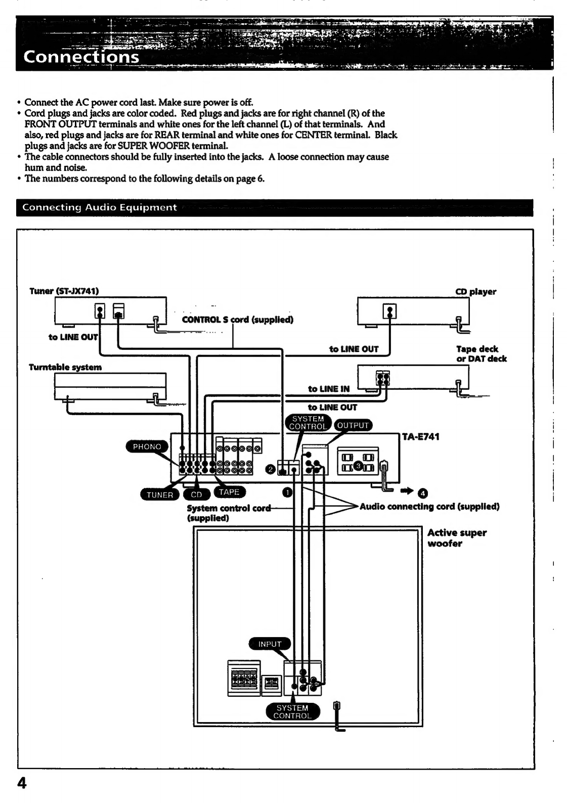
Connecting
audio
equipment
.......
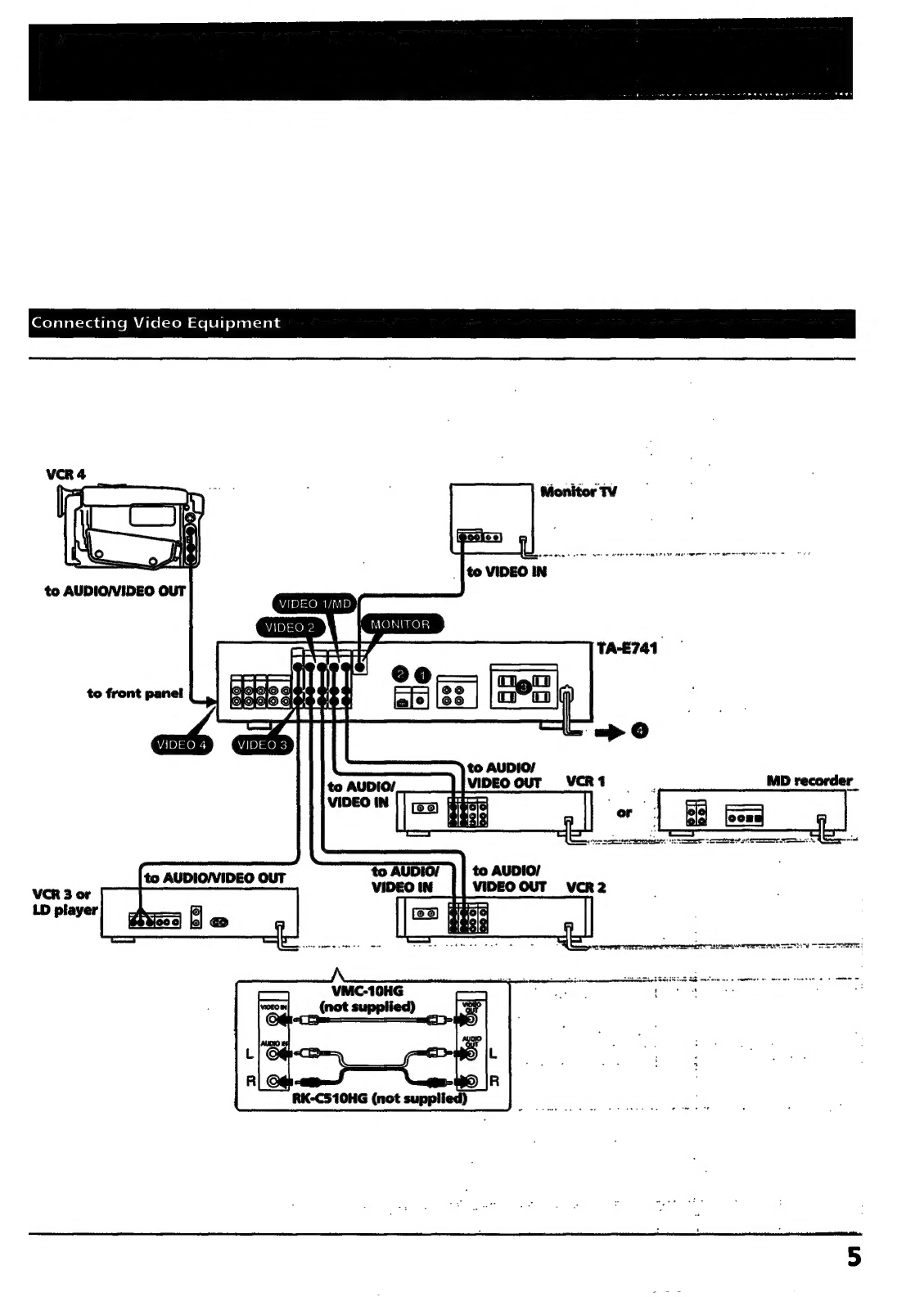
Connecting
video
equipment
....
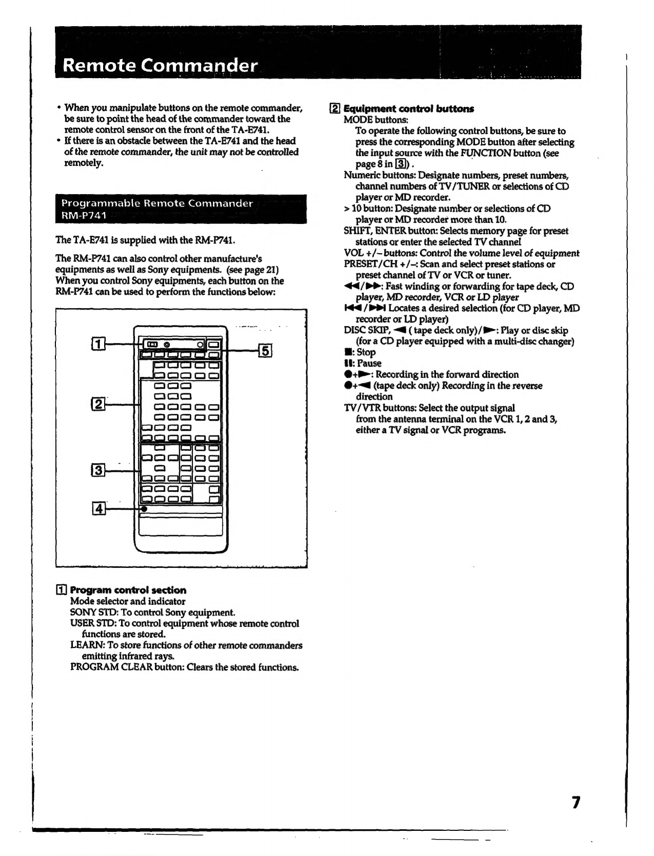
Remote
commande’............sscescserssssererssesssescsssececeeceresssorecsvenssoss
Programmable
remote
commander
RM-P741
Inserting
the
batteries
............0-0scssserssrssreeseerversesssessvess
ore
ee
POoeeoeeocccrooeroovooooors
Using
Your
Stereo
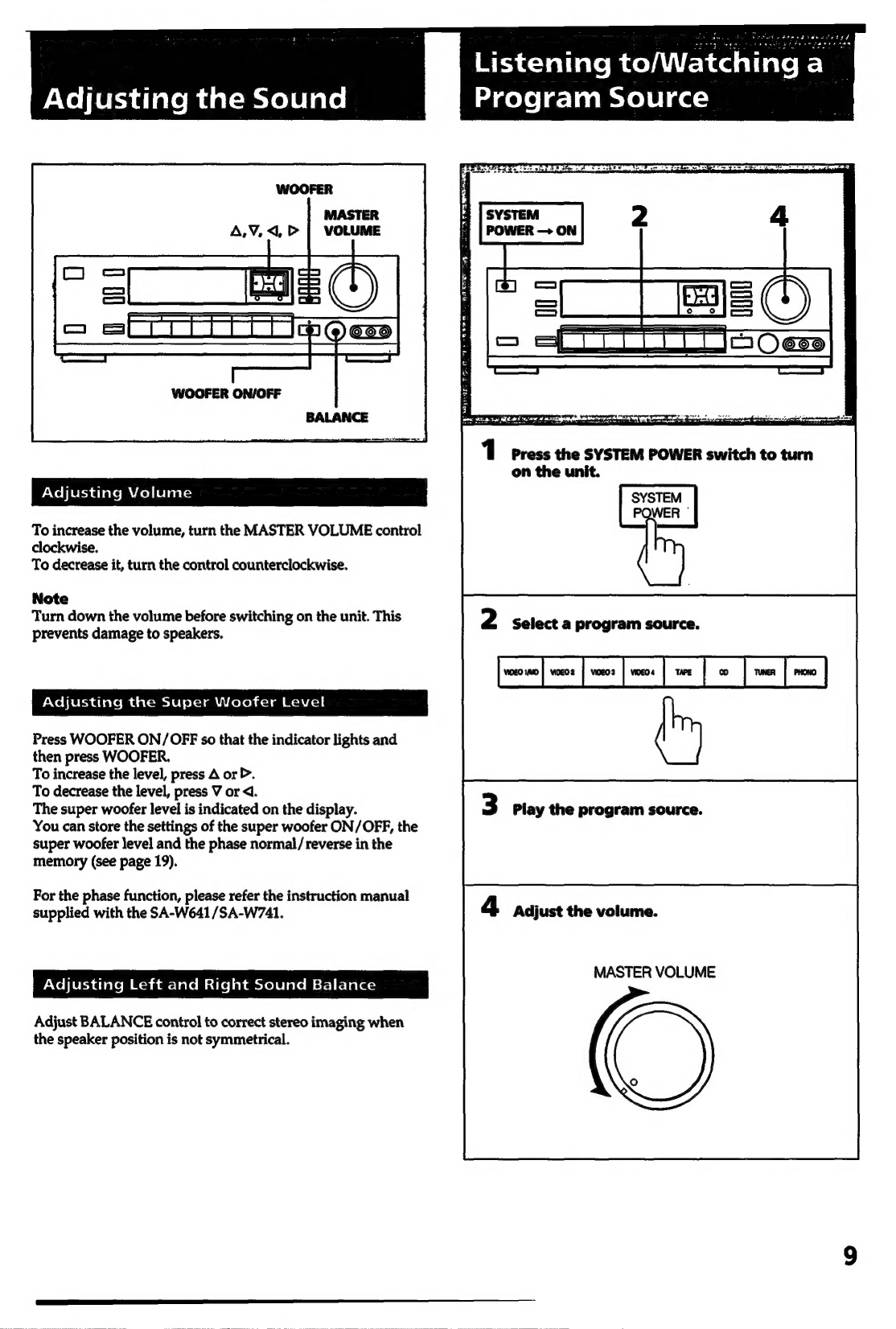
Adjusting
the
Sound
.............ssssssssssssoseesncssecsrsrncesssnvesessesessceessees
9
Adjusting
VOIUME
........csvscssvsrscrsecssssecessesvessesnscesenvssnssresscenneneees
9
Adjusting
the
super
woofer
level
Adjusting
left
and
right
sound
balance............rsscssesesscsesesessene
9
Listening
to/
watching
a
program
SOUICE
.........svcsssseresserersveess
9
Combining
the
video
image
with
the
sound
from
another
program
SOUICE
.......srseceesrsesseee
stitarseasese
LO
Recording
audio
program
SOULCE
........s..sscssescsserserscsseneencensenees
11
Recording
video
program
SOUICE
.........sscscsssssecsscresssereeeenceseess
11
Editing
audio/video
program
SOUICES
..........scrsssessrsrecenseees
12
Getting
ready
to
enjoy
Surround
SOU
........ssssrsssesrsesersessrs
13
Basic
surround
SYSteM
.......c.sssssssssesssesssesssecssessnsessssseseessensceses
13
Selecting
the
speaker
operation
mode
for
SUTTOUNA
SOU
..........rerereererseeee
saasseson
asdsanecussaasieessesaesees
13
Adjusting
the
surround
level
for
Dolby
surround
System
.........sssssecsessssesserecevsescesscaveeseseees
15
Enjoying
the
surround
sound
.
ssnssoussossussnetonsoussbcos
16
Listening
to
with
surround
sound............»
stsasectes
ssssseseeeses
16
Adjusting
the
equalizer
Curve
...........ssssssscsssssvscersesreseecesneeeseese
17
Characteristics
of
each
frequency
..........susssseessersesseererseeevseeee
17,
Enjoying
sound
field
.........sssseccseccsscssneessseersecssneessneerseeesseeenseess
1B
Characteristics
of
the
SOUND
FIELD
program
......s.ssecsss
18
Listening
with
factory
sound
field
settings
...........s+sessssese
Filing
you
own
sound
field
.........ssvscsssecssscessecenes
Storing
an
individual
adjustment-User
file
Recalling
a
stored
adjustment-in
user
file
.........ssssssseosssesses
Advanced
operating
with
the
remote
commandet...........0+
20
Programming
signals
of
other
audio/video
equipment
with
RM-P741
.........ccssssressssesessernsersscesecseccenceseees
20
To
program
a
new
signal
onto
a
previously
Programmed
DuULtON
.........ccrcrscrecsecrseresenecsessessnececensssecenseneees
21
Controlling
equipMen
.........scssereccseresesecersrsesssseseseesooensessesees
21
General
Specifications
..........s.rsesescererereeesenesesrseesecansenessncrecsncaassanesncansenes
22
Troubleshooting
..........0.+-rssssessceeeeseseenernssessssoeseenerscsnesessorsoees
23