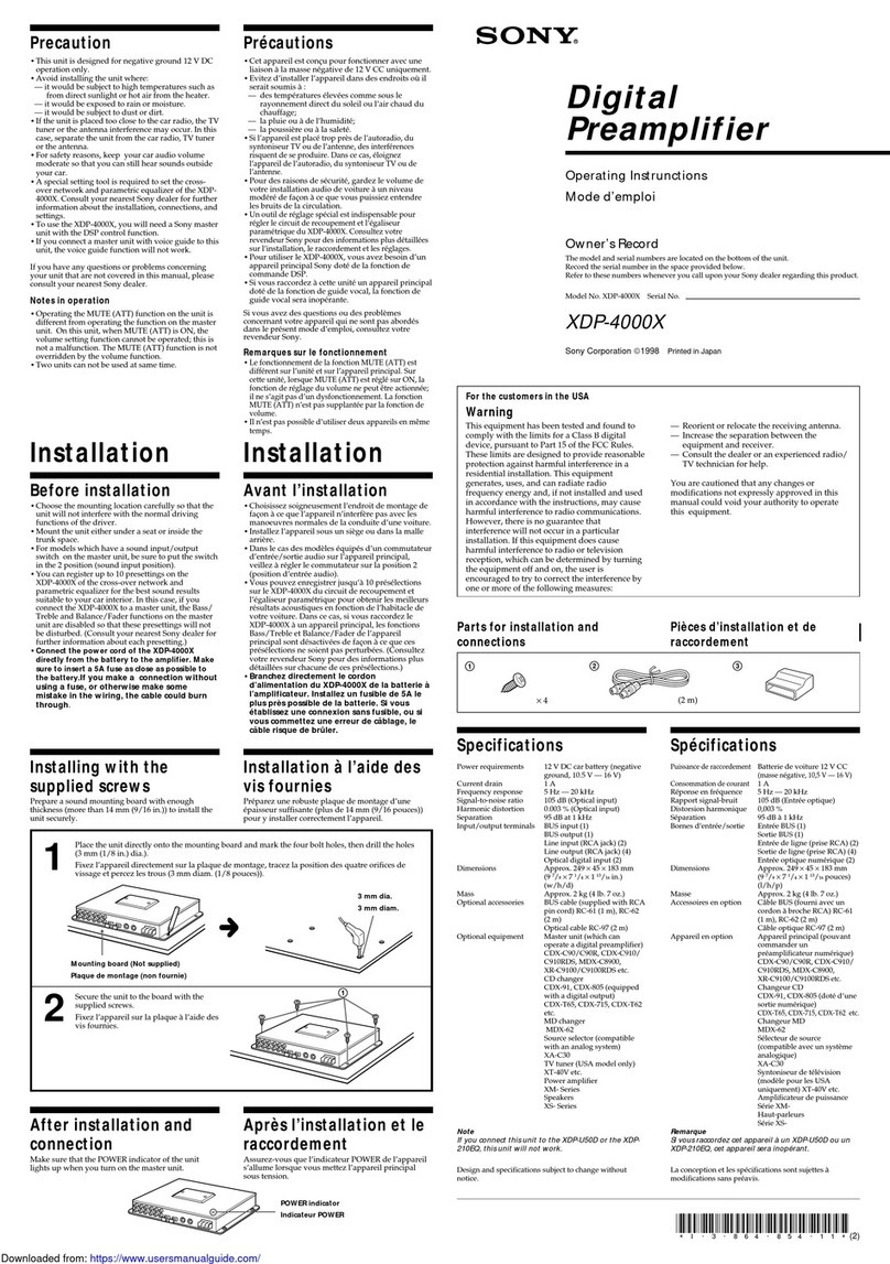
Sony TA-V7700 User manual

S
O
N
YY.
3-786-048-11
(1)
Stereo
Amplifier
Operating
Instructions
_
page
2
Before
operating
the
unit,
please
read
this
manual
thoroughly
and
retain
it
for
future
reference.
Mode
d’emploi
page
14
Avant
la
mise
en
service
de
cet
appareil,
priére
de
lire
attentivement
ce
mode
d’emploi
que
l’on
conservera
pour
toute
référence
ultérieure.
Manual
de
instrucciones
_
pagina
26
Antes
de
utilizar
1a
unidad,
lea
este
manual
detenidamente
y
consérvelo
para
futuras
referencias.
©
1988
by
Sony
Corporation

WARNING
To
prevent
fire
or
shock
hazard,
do
not
expose
the
unit
to
rain
NOTICE
FOR
THE
CUSTOMERS
IN
THE
UNITED
or
moisture.
KINGDOM
To
avoid
electrical
shock,
do
not
open
the
cabinet.
Refer
The
mains
lead
plug
of
this
apparatus
is
a
2-pin
type
servicing
to
qualified
personnel
only.
designed
to
be
connected
only
to
other
apparatus
equipped
with
a
suitable
socket
outlet.
If
the
plug
cannot
be
used
in
this
way,
cut
off
the
plug
and
fit
an
appropriate
one
as
follows:
IMPORTANT
The
wires
in
this
mains
lead
are
coloured
in
accordance
with
the
following
code:
Blue:
Neutral
Brown:
Live
As
the
colours
of
the
wires
in
the
mains
lead
of
this
apparatus
may
not
correspond
to
the
coloured
markings
identifying
the
terminals
in
your
plug,
proceed
as
follows:
The
wire
which
is
coloured
blue
must
be
connected
to
the
terminal
which
is
marked
with
the
letter
N
or
coloured
black.
The
wire
which
is
coloured
brown
must
be
connected
to
the
terminal
which
is
marked
with
the
letter
L
or
coloured
red.
WARNING
To
prevent
shock
hazard,
do
not
insert
the
plug
cut
off
from
the
mains
lead
into
a
socket
outlet.
This
plug
cannot
be
used
and
should
be
discarded.
WE:
|e)
(We)
m
Gre
yal
(alt
Overview
......
Precautions
.
Se
Installation
cesses
ing
Started
Connecting
the
system
ee
Notes
on
connection
Overail
connection
diagram
Parts
identification
8
Audio
adjustment
e
Listening
to
an
audio
program
source
Using
Your
Amplifier
PROGOFCHI
Gy
esis
Sic
sastuaca
casket
cnc
ct
hedeocigsuaant
bates
eae
tvecbg
RUAN
Se
Mecpudletesabaitl
Tape-to-tape
recording
oe
Troubleshooting
Be
~mfpubleshiotitig
Guide
uel oon
sbe
cen
creel
a
co
ae
OE
a
taal
ue
east
13
o
_
Getting
into
the
SPeChfiCatlOnis'secacccscczsascsicscencsbaschacy
See
acancucdaecsiacledecd
sued
ea
casachecwlasieacdadeslvesatlbsacealbtasatedRneceartacdiccastisateanes
13
Details
7
Aeleliea
¢
Power
output
is
80
W
+
80
W
(at
6
ohms).
¢
OPTICAL
DIGITAL
IN
connectors
for
DAT
(Digital
Audio
Tape)
deck
and
CD
player
are
provided
for
listening
to
a
digital
sound
source.
*
Tape-to-tape
recording
can
be
performed
using
the
REC
OUT
SELECTOR
and
the
INPUT
SELECTOR.
ea
csvers1U
bie)
ats
On
operating
voltage
Before
operating
the
unit,
check
that
the
operating
voltage
of
your
unit
is
identical
with
the
voltage
of
your
local
power
supply.
|
Operating
voltage
|
240
V
AG
|
Where
purchased
|
United
Kingdom
Continental
European
countries
Cae
On
safety
e
The
unit
is
not
disconnected
from
the
AC
power
source
as
long
as
it
is
connected
to
the
wall
outlet,
even
if
the
unit
itself
has
been
turned
off.
e
Unplug
the
unit
from
the
wall
outlet
if
it
is
not
to
be
used
for
an
extended
period
of
time.
To
disconnect
the
cord,
pull
it
out
by
the
plug.
Never
pull
the
cord
itself.
¢
Should
any
solid
object
or
liquid
fall
into
the
unit,
unplug
the
unit
and
have
the
unit
checked
by
qualified
personnel
before
operating
it
any
further.
On
cleaning
the
cabinet
Clean
the
cabinet,
panels
and
controls
with
a
soft
cloth
lightly
moistened
with
a
mild
detergent
solution.
Do
not
use
any
type
of
abrasive
pad,
scouring
powder
or
solvent
such
as
alcohol
or
benzine.
On
repacking
Do
not
throw
away
the
carton
and
the
packing
material.
This
makes
an
ideal
container
when
transporting
the
unit.
When
shipping
the
unit,
repack
it
as
it
was
packed
at
the
factory.
If
you
have
any
question
or
problem
concerning
your
unit,
please
consult
your
nearest
Sony
dealer.
Yo)
CetoMol
aM
latsyecliFcliceya
Place
the
unit
in
a
location
with
adequate
air
circulation
to
prevent
internal
heat
build-up
in
the
unit.
Do
not
place
anything
on
top
of
the
unit.
The
ventilation
holes
must
be
unobstructed
for
proper
operation
of
the
unit
and
to
prolong
the
life
of
its
components.
Not
this
way.

Connecting
the
System
Noy
ctomela
Mm
Oxelaarsverteln
¢
Connect
the
AC
power
cord
last.
Make
sure
power
is
off.
*
Cord
plugs
and
jacks
are
color
coded.
Red
plugs
and
jacks
are
for
right
channel
(R)
and
white
ones
for
left
channel
(L).
«
Fully
insert
cable
connectors
into
jacks.
Loose
connections
may
cause
hum
or
noise.
Overall
Connection
Diagram
Turntable
system
Graphic
equalizer
7
ey
3
Digital
audio
tape
Left
speaker
Right
speaker
toan
AC
outlet
Double
cassette
deck
Cassette
deck
VTR
or
CD
player
@connecting
a
turntable
system
=
cea
TA-V7700
Turntable
system

[
@connecting
a
tuner
Tuner
tt
to
line
outputs
RK-C74
TA-V7700
r
C3)
Connecting
a
graphic
equalizer
Graphic
equalizer
—
ee
eee
FPEE
PEE
unc
PEEFEPE
44
4¢
to
line
inputs
RK-C74
to
line
RK-C74
outputs
Be
sure
to
turn
OFF
(released)
ADAPTOR
when
the
ADAPTOR
jacks
are
not
used.
If
not,
sound
cannot
be
heard.
TA-V7700
LL
@
Connecting
a
DAT
(digital
audio
tape)
deck
1
Remove
the
cap.
Insert
the
RK-C74
to
optical
digital
output
Optical
digital
cord
(supplied)
Note
on
DAT
deck
connection
When
the
DAT
OUT
jacks
are
used
for
DAT
deck
connection,
do
not
connect
another
DAT
deck
to
the
REC
OUT
jacks
of
TAPE
2.
If
it
is
connected
to
the
TAPE
2
REC
OUT
jacks,
oscillation
may
occur.
TA-V7700
Sy
[Mia

Connecting
the
System
@
Connecting
cassette
decks
(For
TAPE
1,
be
sure
to
use
a
Sony
TC-V7700
or
TC-V715T
double
cassette
deck.)
Cassette
deck
TA-V7700
llcko)
°
He
AF
to
4t
to
line
line
inputs
outputs
RK-C74
©
Connecting
a
VTR
or
CD
player
TA-V7700
=
44
to
line
inputs
VTR
oo
RK-C74
to
line
outputs
RK-C74
@
Connecting
a
CD
player
having
an
optical
output
jack
TA-V7700
CD
player
==3
asa
a4455
ee
PE
oy
t
to
optical
digital
output
Optical
digital
cord
(supplied)

©
Connecting
left
and
right
speakers
|
Right
speaker
Left
speaker
TA-V7700
be
J
©
Connect
the
AC
power
cord
of
other
audio
component
whose
total
power
consumption
is
less
than
the
wattage
indicated
near
the
AC
OUTLET.
TA-V7700
ce
MA)
Sectors
QO
GIO
Audio
component
manay
to
a
wall
outlet
CAUTION
Do
not
connect
any
electrical
home
appliance
such
as
an
The
unswitched
socket
outlet
remains
live,
independently
electric
iron,
fan,
TV
or
other
high-wattage
equipment
to
this
of
power
switch
setting,
at
all
times
when
the
unit
is
AC
outlet.
connected
to
the
AC
power
supply.
@
Connect
the
AC
power
cord,
making
sure
that
the
POWER
switch
is
OFF.
TA-V7700
sp
to
a
wail
outlet

Parts
Identification
Refer
to
the
pages
indicated
in
@
for
details.
POWER
switch
REC
OUT
(recording
output)
SELECTOR
INPUT
SELECTOR
OPTICAL
DIGITAL
SOURCE
selector
SOURCE
DIRECT
switch
and
indicator
ATTENUATOR
PURE
&
DYNAMIC_OPTICAL
DIGITAL
UAL
D/A
CONVERTER
/
GBAALTAL
CHASSSS
REC
OU
|
SELECTOR
ae
INCUT
S
OR
.~
OPTICAL
DIG
FAL
SOURCE,
ch
V7700
«PEF
OPTICAI
DIGITAL
CO/DAT/BS
+ *
SOURCE
—
TAPET.
+
«TUNER:
BALANCE
ADAPTOR
switch
BALANCE
control
TREBLE
control
BASS
control
BASS
BOOST
switch
PROTECTORIDIGITAL
SOURCE
indicators
HEADPHONES
jack

PANTTolCommANeliUCyataleyal
Volume
Adjustment
To
adjust
volume
Turn
ATTENUATOR
clockwise
to
increase
volume.
Turn
it
counterclockwise
to
decrease
volume.
Before
turning
ON
the
power,
turn
ATTENUATOR
fully
counterclockwise
(ce
dB)
to
avoid
damage
to
the
speakers.
ATTENUATOR
Sound
Quality
Adjustment
To
adjust
the
tone
quality
Turn
TREBLE
clockwise
to
increase
treble
sound.
Turn
BASS
clockwise
to
increase
bass
sound.
BASS
TREBLE
6
6
6
6
8 8 8 8
-19
+10
-10
+10
To
increase
bass
sound
Depress
BASS
BOOST.
Normally,
set
the
switch
to
OFF
(released).
BASS
BOOST
coon
[|]
oFF
Graphic
Equalizer
Depress
ADAPTOR.
Be
sure
to
turn
OFF
(released)
ADAPTOR
when
the
ADAPTOR
jacks
are
not
used.
If
not,
sound
cannot
be
heard.
When
a
graphic
equalizer
is
connected
Turn
ON
the
ADAPTOR
switch.
ADAPTOR
‘=o
ro
ON
(]
OFF
Balance
Adjustment
To
change
the
relative
strength
of
the
left
and
right
speaker
output
Adjust
BALANCE
to
correct
stereo
imaging,
when
the
speaker
position
is
not
symmetrical.
BALANCE
LEFT
®
RIGHT
To
listen
to
the
sound
input
to
the
unit
without
passing
through
the
circuits
of
tone
controls
Depress
SOURCE
DIRECT.
The
indicator
lights
up
and
the
circuits
of
BASS
BOOST,
BASS,
TREBLE
and
BALANCE
controls
are
disengaged.
To
use
the
TREBLE
and
BASS
controls,
BASS
BOOST
switch
and
the
connected
graphic
equalizer
simultaneously
Turn
the
controls
slowly
from
the
standard
position
by
confirming
the
sound
effect.
If
not,
sound
may
be
distorted.
9

My
cclaliavem
comr-lamaverel(omaaceyele-Lamerelelce=
1
Turn
on
POWER
and
the
connected
components.
bi
ec
ea
ae
4
a5
2
Set
INPUT
SELECTOR
and
OPTICAL
DIGITAL
4
.
2
CRUSE
eRe
ee
SOURCE
to
your
desired
position.
Desired
sound
source
INPUT
OPTICAL
SELECTOR
|
DIGITAL
SOURCE
selector
cD
am
or
audio
signal
progr
ce
of
VTR
VIDEO/CD
Taped
program
connected
=
to
TAPE
1
inputs
dee
Taped
program
connected
_
to
TAPE
2
inputs
TAPE
2
CD
program
connected
to
OPTICAL
DIGITAL
IN
(CD)
Dante
cD
connector
Digital
audio
taped
program
connected
to
OPTICAL
DAT
OPTICAL
DIGITAL
IN
DIGITAL
(DAT)
connector
Radio
program
TUNER
_
Record
program
PHONO
_
3
Play
the
program
source.
4
Adjust
the
sound
level
with
ATTENUATOR.
When
you
turn
on
the
power
For
private
listening
The
PROTECTOR
indicator
lights
up
for
approx.
five
seconds
Connect
headphones
to
the
HEADPHONES
jack.
Speaker
sound
immediately
after
the
power
turns
on
and
goes
out.
is
automatically
disconnected.
The
PROTECTOR
indicator
also
lights
up
when
the
condition
is
abnormal.
When
a
CD
player
and/or
DAT
deck
are
connected
to
the
OPTICAL
DIGITAL
IN
connectors
The
“CD”
and
“DAT”
DIGITAL
SOURCE
and
OPERATING
indicators
light
up
without
regard
to
the
setting
of
the
INPUT
SELECTOR
while
power
of
the
connected
CD
player
and
DAT
deck
is
on.
10

aicvexol
collate!
1
Turn
on
POWER
and
the
connected
components.
2
Set
REC
OUT
SELECTOR
to
SOURCE.
3
Set
INPUT
SELECTOR
and
OPTICAL
DIGITAL
SOURCE
to
the
proper
position.
Audio
program
source
to
INPUT
OPTICAL
be
recorded
SELECTOR
|DIGITAL
SOURCE
selector
CD
program
or
audio
signal
of
VIR
VIDEO/CD
Taped
program
connected
to
TAPE
1
inputs
je
Taped
program
connected
to
TAPE
2
inputs
aE
e
CD
program
connected
to
OPTICAL
fee
TAPE
1
—
OPTICAL
DIGITAL
IN
(CD)
DIGITAL
cD
connector
Digital
audio
taped
program
connected
to
OPTICAL
alts
DAT
DIGITAL
IN
(DAT)
connector
Radio
program
TUNER
_
Record
program
PHONO
_—
4
Play
the
program
source
to
be
recorded.
5
Set
the
connected
cassette
deck
and/or
VTR
in
the
record
mode.
To
record
source
sound
on
DAT
deck
Be
sure
to
set
OPTICAL
DIGITAL
SOURCE
to
CD.
WW

istcrerelceliale|
by
the
INPUT
SELECTOR
can
be
made.
The
unit
allows
tape
dubbing
between
the
connected
cassette
decks
and
VTR.
See
the
following
chart.
[
Setting
of
REC
Tape-to-Tape
Recording
Recording
while
listening
to
another
program
sound
selected
Recording
on
the
equipment
connected
to
OUTSELECTOR
|
tape
1
TAPE
2
VIDEO/CD
DAT
OUT
jacks
REC
OUT
jacks
=|
REC
OUT
jacks
|
OUT
jacks
OPTICAL
DIGITAL
|
OPTICAL
DIGITAL
sees
signal
SOURCE
selector:
|
SOURCE
selector:
is
output.)
CD
position
DAT
position
TAPE
1
Recording
is
Recording
is
Recording
is
Recording
is
Signal
is
not
output
(Sony
TC-V7700
possible. possible. possible.
possible.
though
REC
OUT
of
or
TC-V715T
DAT.
double
cassette
deck
only)
TAPE
2
Recording
is
Signal
is
not
Recording
is
possible.
output.
possible.
CD/DAT
Recording
is
Recording
is
Recording
is
|
possible.
possible. possible.
To
record
the
sound
through
the
connected
graphic
equalizer
Depress
ADAPTOR
ON.
The
sound
equalized
by
the
graphic
equalizer
can
be
recorded
only
when
the
REC
OUT
SELECTOR
is
set
to
SOURCE.
12
To
disconnect
the
output
signals
Set
REC
OUT
SELECTOR
to
OFF.

MicolUie)(=\-yatereiiatemerulre(=
Before
going
through
the
check
list
below,
first
refer
back
to
the
connection
and
operating
procedures.
Should
any
problem
persist
after
you
have
made
these
checks,
consult
your
nearest
Sony
dealer.
Trouble
Cause
_
No
audio
No
audio
from
one
channel
or
unbalanced
left
and
right
sound
level.
|
No
recording
position
|
Lack
of
bass
sound
or
obscure
instrument
©
Faulty
setting
of
INPUT
SELECTOR.
¢
Faulty
connection
«The
ADAPTOR
switch
is
set
to
ON
when
the
ADAPTOR
jacks
are
not
used.
¢
The
equipment
connected
to
the
ADAPTOR
jacks
is
not
turned
on.
—
¢
Set
it
correctly.
¢
Connect
the
unit
and
other
equipments
correctly.
¢
Turn
OFF
the
ADAPTOR
switch.
=
Remedy
¢
Set
the
ADAPTOR
switch
to
ON
or
turn
on
the
equipment.
Incorrect
setting
of
the
BALANCE
control.
Set
the
BALANCE
correctly.
Severe
hum
or
noise
The
REC
OUT
SELECTOR
is
not
correctly
|
Set
the
selector
correctly.
set.
Mal-setting
of
sound
quality
controls
e
Noise
from
TV,
etc.
¢
Faulty
connection
of
turntable
system
©
Connect
correctly.
Ground
the
turntable
system.
Adjust
the
controls
for
sound
quality.
¢
Keep
the
connecting
cords
away
from
transformers
or
motors,
TV
and
fluorescent
lights.
Specifications
Continuous
RMS
power
(both
channels
driven)
Music
power
output
80
W
+
80
W
(6
ohms)
at
1
kHz
70
W
+
70
W
6
ohms)
at
40
Hz
—
20
kHz
300
W
Harmonic
distortion
Less
than
0.02%
at
rated
output
1M
distortion
(60
Hz:
7
KHz
=
4:
1)
Less
than
0.02%
at
rated
output
Frequency
response
PHONO:
RIAA
equalization
curve
+0.5
dB
TUNER
|
TAPE
1,
2
7
+0
VIDEOICD
|
10
Hz
-
50
kHz_-5dB
ADAPTOR
Residual
noise
Less
than
130
pV
(6
ohms
network
A)
Input
joey
S/N
(network,
|
Input
|
Sensitivity
Impedance
input
level)
|
PHONO
2.0
mV
50
kohms
70
dB
{A,
2.0
mV)
TUNER
TAPE
1,2
91
dB
y
V
vipeocp.
=|
O™
SOkohms
|
(a,
150
mV)
ADAPTOR
Tens
DA
converter
Frequency
4Hz-20kHz2+3.dB
SIN
More
than
95
dB
Outputs
Output
Type
Voltage
Impedance
DAT
OUT
ADAPTOR
TAPE
1,2
Phono
150
mV
1kohms
VIDEO
HEAD-
Stereo
Accepts
headphones
of
8
ohms
PHONES
phone
or
more.
a
|
Tone
controls
BASS
+10
dB
(at
100
Hz)
TREBLE
+10
dB
(at
10
kHz)
BASS
BOOST
+10
dB
(at
20
Hz,
1W)
General
Power
requirements
Model
for
continental
European
countries:
220
V
AC,
50/60
Hz
Model
for
United
Kingdom:
240
V
AC,
50/60
Hz
Power
consumption
Model
for
continental
European
countries:
150
W
Model
for
United
Kingdom:
350
W
AC
outlet
1
Unswitched,
200
W
max.
Dimensions
Approx.
355
x
130
x
368
mm
(w/h/d)
Weight
Approx.
10.2
kg
(22
ib
8
02),
net
Design
and
specifications
subject
to
change
without
notice.
13
Table of contents
Other Sony Amplifier manuals

Sony
Sony XM-SD14X User manual

Sony
Sony PHA-1AEU User guide

Sony
Sony Xplod XM-5040X User manual

Sony
Sony TA-E741 User manual

Sony
Sony WAHT-SA10 - Wireless Audio Delivery System User manual

Sony
Sony TA-VE215 User manual

Sony
Sony XM-D9001GTR User manual

Sony
Sony XM-DS1300P5 Operating & Mounting User manual

Sony
Sony TA-FB940R User manual

Sony
Sony STR-AN1000 Reference guide

Sony
Sony TA-AV411 User manual

Sony
Sony TA-V901 User manual

Sony
Sony TA-FE320R User manual

Sony
Sony TA-P9000ES - Amplifier User manual

Sony
Sony TA-AV431 User manual

Sony
Sony XM-N1004 User manual

Sony
Sony TA-AV411 User manual

Sony
Sony WM-EX368 User manual

Sony
Sony TA-FB730R User manual

Sony
Sony XM-SD22X User manual