1
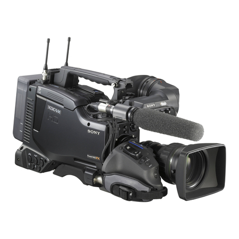
PMW-EX1
Table of Contents
2-2-10. RE-250 Board/ RE-251 Board ............................ 2-10
2-2-11. Battery Case, TX-115 Board ...............................2-11
2-2-12. DPR-289 Board ................................................... 2-13
2-2-13. Case L Assembly ................................................. 2-14
2-2-14. Case R Assembly ................................................ 2-15
2-2-15. Prism Assembly ................................................... 2-15
2-2-16. ND Filter ............................................................. 2-16
2-2-17. AU-313 Board, JK-77 Board,
SW-1375 Board ................................................... 2-17
2-2-18. LENS UNIT ........................................................ 2-17
2-2-19. DR-621 Board ..................................................... 2-18
2-2-20. LED-465 Board ................................................... 2-19
2-2-21. Speaker ................................................................ 2-19
2-2-22. KSW-53 Board, HN-320 Board ..........................2-20
2-2-23. Microphone Unit Assembly ................................ 2-21
2-2-24. Microphone Unit ................................................. 2-22
2-2-25. DET-44 Board ..................................................... 2-23
2-2-26. 3.5-inch LCD Assembly ......................................2-24
2-2-27. Replacing the Parts in the Lens Grip ...................2-25
3. SERVICE Menu
3-1. SERVICE Menu List ...................................................... 3-1
3-2. SERVICE Menu Description .......................................... 3-3
3-2-1. Basic Menu Operations ......................................... 3-3
3-2-2. SERVICE Menu Structure ....................................3-3
3-2-3. Displaying the SERVICE Menu ........................... 3-3
3-3. SERVICE Menu Description .......................................... 3-3
3-3-1. MAINTENANCE Menu ....................................... 3-3
3-3-2. RPN CORRECT Menu ......................................... 3-7
3-3-3. INFORMATION Menu ......................................... 3-8
4. Alignment
4-1. Servicing software “ServiceNavi-EX” ........................... 4-1
5. Spare Parts
5-1. Notes on Repair Parts ..................................................... 5-1
5-2. Exploded Views .............................................................. 5-2
5-3. Electrical Parts List .......................................................5-17
5-4. Supplied Accessories .................................................... 5-55
6. Semiconductor Pin Assignments
Manual Structure
Purpose of this manual ................................................................. 4
Related manuals ........................................................................... 4
1. Service Overview
1-1. External Connectors ........................................................ 1-1
1-1-1. Signal Inputs and Outputs ..................................... 1-1
1-2. Location of the Printed Wiring Boards ........................... 1-3
1-3. Circuit Description .......................................................... 1-4
1-4. Service Tools/Measuring Equipment List .................... 1-10
1-4-1. Service Tools ....................................................... 1-10
1-4-2. Measuring Equipment ......................................... 1-10
1-5. Firmware Upgrade ........................................................ 1-11
1-6. Recommended Replacement Parts ............................... 1-12
1-7. Note on Service ............................................................. 1-13
1-7-1. Requirements on Replacement of Boards
or Parts ................................................................. 1-13
1-7-2. Requirements on Replacement of Lens ............... 1-13
1-7-3. Note on Replacement of Parts on the Board ....... 1-13
1-7-4. Description of Number Seal on the Prism ........... 1-13
1-7-5. Memory Backup Battery ..................................... 1-13
1-7-6. Unleaded Solder .................................................. 1-13
1-8. Connector Location Diagram on Board ........................ 1-14
1-9. Replacing the Flexible Card Wires ...............................1-14
1-10. Replacing the Coaxial Cable with Connector
(Fine Pitch Coaxial Cable) ............................................ 1-15
1-11. List of Error Numbers on the LCD Display ................. 1-16
2. Replacement of Main Parts
2-1. Outline of Replacement Procedures ............................... 2-1
2-2. Replacement Procedures ................................................. 2-2
2-2-1. Lithium Battery ..................................................... 2-2
2-2-2. Case (Bottom) L/R and Front Panel Assembly ..... 2-2
2-2-3. Microphone Holder Assembly ..............................2-3
2-2-4. EVF Assembly ...................................................... 2-4
2-2-5. Handle Assembly .................................................. 2-5
2-2-6. BP-43 Board ..........................................................2-6
2-2-7. Inside Panel Assembly/Outside Panel
Assembly ............................................................... 2-6
2-2-8. Rear Panel Assembly ............................................ 2-7
2-2-9. Express Card Assembly ........................................ 2-8

