1 (E)
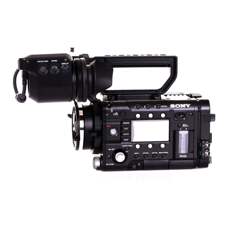
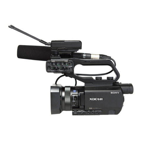
PMW-EX1R
Table of Contents
Manual Structure
Purpose of this manual............................................................ 3 (E)
Related manuals...................................................................... 3 (E)
1. Service Overview
1-1. External Connectors ..................................................1-1 (E)
1-1-1. Signal Inputs and Outputs................................1-1 (E)
1-2. Location of the Printed Wiring Boards .....................1-3 (E)
1-3. Circuit Description ....................................................1-4 (E)
1-4. Service Tools/Measuring Equipment List ...............1-12 (E)
1-4-1. Service Tools..................................................1-12 (E)
1-4-2. Measuring Equipment.................................... 1-12 (E)
1-5. Firmware Upgrade...................................................1-13 (E)
1-6. Recommended Replacement Parts..........................1-14 (E)
1-7. Circuit Protection Part List...................................... 1-15 (E)
1-7-1. Circuit Protection Element.............................1-15 (E)
1-7-2. Replacing Fuse............................................... 1-15 (E)
1-8. Note on Service .......................................................1-16 (E)
1-8-1. Requirements on Replacement of Boards
or Parts ...........................................................1-16 (E)
1-8-2. Requirements on Replacement of Lens .........1-16 (E)
1-8-3. Note on Replacement of Parts on
the Board........................................................1-16 (E)
1-8-4. Description of Number Seal on the Prism .....1-16 (E)
1-8-5. Memory Backup Battery................................ 1-17 (E)
1-8-6. Unleaded Solder............................................. 1-17 (E)
1-9. Connector Location Diagram on Board ..................1-18 (E)
1-10. Connecting/Disconnecting the Flexible
Card Wire ................................................................ 1-19 (E)
1-11. Replacing the Coaxial Cable with Connector
(Fine Pitch Coaxial Cable) .......................................... 1-20 (E)
2. Replacement of Main Parts
2-1. Outline of Replacement Procedures .........................2-1 (E)
2-2. Replacement Procedures ...........................................2-2 (E)
2-2-1. Lithium Battery ...............................................2-2 (E)
2-2-2. Case (Bottom) L/R and Front Panel
Assembly .........................................................2-2 (E)
2-2-3. Microphone Holder Assembly ........................2-4 (E)
2-2-4. EVF Assembly ................................................. 2-4 (E)
2-2-5. Handle Assembly ............................................. 2-5 (E)
2-2-6. DAP-41 Board and AU-326 Board..................2-7 (E)
2-2-7. SW-1478 Board................................................2-8 (E)
2-2-8. Inside Panel Assembly/Outside Panel
Assembly .........................................................2-8 (E)
2-2-9. Rear Panel Assembly .....................................2-10 (E)
2-2-10. Express Card Assembly ................................. 2-11 (E)
2-2-11. RE-272 Board and RE-273 Board .................2-12 (E)
2-2-12. Battery Case, TX-131 Board .........................2-13 (E)
2-2-13. DPR-311 Board..............................................2-15 (E)
2-2-14. Case L Assembly............................................2-16 (E)
2-2-15. Case R............................................................2-17 (E)
2-2-16. Prism Assembly .............................................2-18 (E)
2-2-17. ND Filter........................................................2-18 (E)
2-2-18. Lens Unit........................................................2-19 (E)
2-2-19. DR-644 Board................................................2-19 (E)
2-2-20. LED-491 Board..............................................2-20 (E)
2-2-21. Speaker...........................................................2-20 (E)
2-2-22. KSW-55 Board, HN-361 Board.....................2-21 (E)
2-2-23. Microphone Unit Assembly ........................... 2-22 (E)
2-2-24. Microphone Unit............................................2-23 (E)
2-2-25. DET-52 Board................................................2-24 (E)
2-2-26. 3.5-inch LCD Assembly ................................2-25 (E)
2-2-27. Replacing the Parts in the Lens Grip .............2-26 (E)
3. SERVICE Menu
3-1. Outline of SERVICE Menu.......................................3-1 (E)
3-1-1. Basic Menu Operations.................................... 3-1 (E)
3-1-2. SERVICE Menu Structure ............................... 3-1 (E)
3-1-3. Displaying the SERVICE Menu ......................3-1 (E)
3-2. SERVICE Menu List.................................................3-2 (E)
3-2-1. MAINTENANCE Menu..................................3-2 (E)
3-2-2. RPN CORRECT Menu....................................3-2 (E)
3-2-3. INFORMATION Menu ...................................3-3 (E)
3-3. Self-Diagnostic Function...........................................3-4 (E)
3-4. Executing Log Dump ................................................3-9 (E)
3-5. List of Error Numbers on the LCD Display............3-10 (E)
