C
SSC-CB575R SSC-CB565R
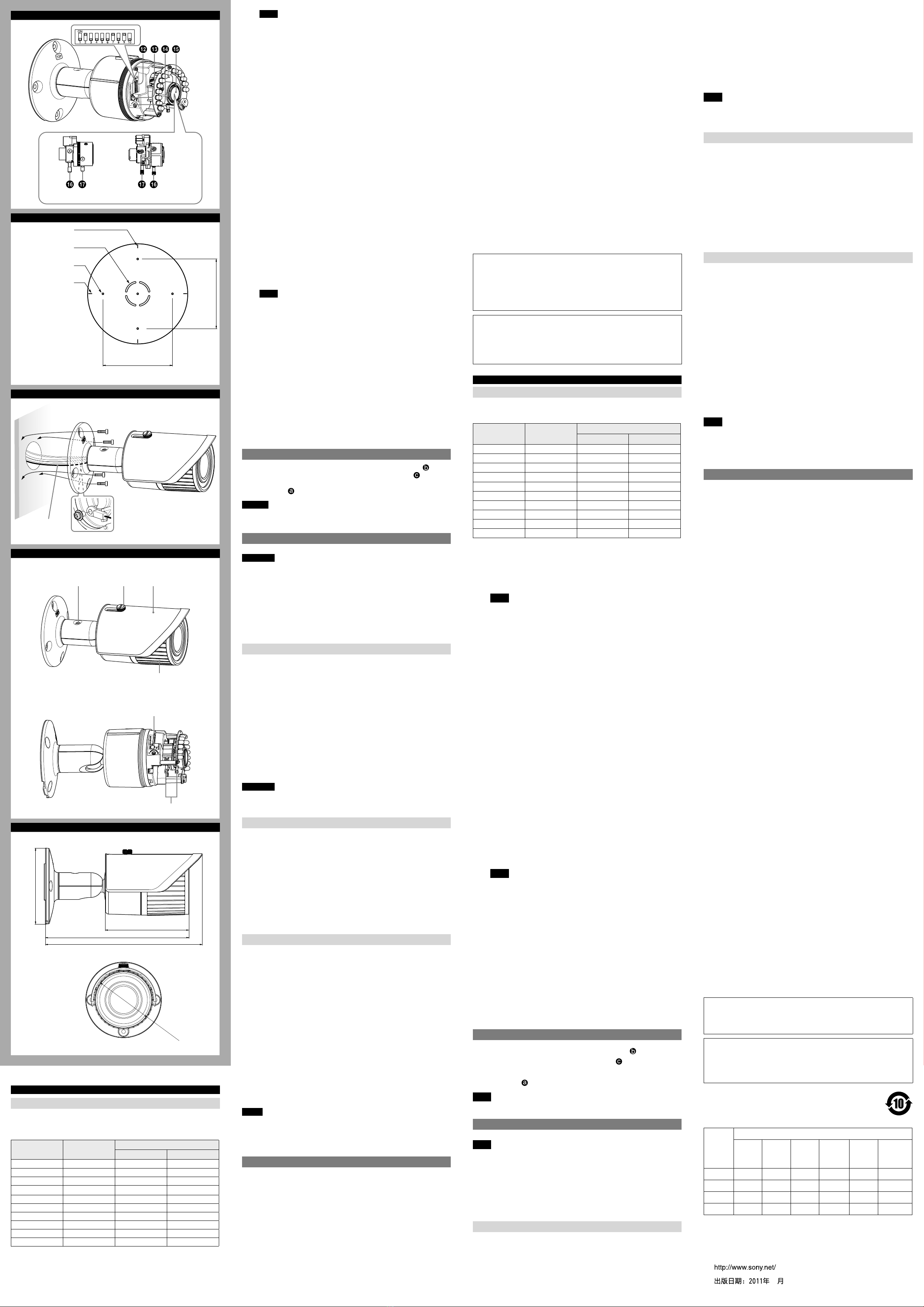
D
83.5
Hole for connecting
cables ø30/
连接电缆孔ø30
Horizontal mark/
水平标记
Hole for installing the
stand/安装底座孔
Vertical mark/
垂直标记
83.5
Unit : mm/单位:mm
E
Wall/墙壁
Fall-prevention
rope (supplied)/
防坠绳(附带)
F
–1
–2
G
ø77
110
189
206.7
Side/边侧
Bottom/底部
ø100
Unit : mm/单位:mm
Horizontal resolution 650 TV lines (normal mode)
Minimum illumination SSC-CB565R:
Color: 0.06 lx at F1.2 (50 IRE, AGC ON)
Color: 0.04 lx at F1.2 (30 IRE, AGC ON)
B/W: 0 lx at F1.2 (50 IRE, AGC ON, IR ON)
B/W: 0 lx at F1.2 (30 IRE, AGC ON, IR ON)
SSC-CB575R:
Color: 0.09 lx at F1.4 (50 IRE, AGC ON)
Color: 0.05 lx at F1.4 (30 IRE, AGC ON)
B/W: 0 lx at F1.4 (50 IRE, AGC ON, IR ON)
B/W: 0 lx at F1.4 (30 IRE, AGC ON, IR ON)
Video output 1.0 Vp-p, 75 Ω, negative sync , BNC cabel
Video S/N 55 dB (AGC OFF, WEIGHT ON)
White balance ATW-PRO/ATW
Automatic gain control (AGC) ON/OFF
Monitor out RCA jack
IR working distance 30 m (50 IRE)
IR Led 14 pcs
Power supply
AC 24V (50 Hz)/DC 12 V
Power consumption 5.5 W
Operating temperature –10°C to +50°C
Storage temperature –40°C to +60°C
Operating humidity 20% to 80%
Storage humidity 20% to 95%
Dimensions (camera body) ø77 mm × 110 mm (not including
projecting parts)
Mass
Approx. 650 g
Supplied accessories Template (1), Fall-prevention rope (1),
Screw M4 × 8 (1), Wrench (1),
Installation Manual (this document) (1 set)
Design and specifications are subject to change without notice.
Note
Always verify that the unit is operating properly before use. SONY WILL NOT BE
LIABLE FOR DAMAGES OF ANY KIND INCLUDING, BUT NOT LIMITED TO,
COMPENSATION OR REIMBURSEMENT ON ACCOUNT OF THE LOSS OF PRESENT
OR PROSPECTIVE PROFITS DUE TO FAILURE OF THIS UNIT, EITHER DURING THE
WARRANTY PERIOD OR AFTER EXPIRATION OF THE WARRANTY, OR FOR ANY
OTHER REASON WHATSOEVER.
Recommendation of Periodic Inspections
In case using this device over an extended period of time, please have it
inspected periodically for safe use.
It may appear flawless, but the components may have deteriorated over time,
which may cause a malfunction or accident.
For details, please consult the store of purchase or an authorized Sony dealer.
中文
内部
模式设定DIP开关
如果下列DIP开关被设定于顶端位置,则它们处于打开状态。
PinNo. 开关 位置
上(ON) 下(OFF)
1 SYNC LL INT
2 AGC ON OFF
3 iBLC ON OFF
4 ATR-Lite ON OFF
5 SHARPNESS SHARP NORMAL
6 WB ATWPRO ATW
7 D/N AUTO OFF
8 D/N_TIME SHORT LONG
9 AdIR ON OFF
10 IRIS OPEN AUTO
1:SYNC(同步锁定)开关(初始设定:INT)
使用此开关将摄像机同步模式设定为INT(内部)或
LL(线路锁定)。
摄像机电源为12V直流电源时,摄像机以内部操作模式工作,
而不管开关设定位置。
注意
如果在摄像机电源不稳定时使用线路锁定功能,摄像机图像可
能会抖动。
2:AGC(自动增益控制)开关(初始设定:ON)
设定为ON时,可使用此开关以提高视频放大器的增益。
3:iBLC(智能逆光补偿)开关(初始设定:OFF)
使用此开关对处于逆光环境的拍摄对象进行曝光补偿。
4:ATR-Lite(适应性色调再生)开关(初始设定:OFF)
此开关设定为ON时,摄像机将根据环境明暗自动调节色调。
5:SHARPNESS(锐度选择)开关(初始设定:NORMAL)
此开关设定为ON时,可以提高摄像机画质的锐度。
6:WB(白平衡)开关(初始设定:ATW)
选择摄像机的WB模式:
ATWPRO(此开关设定为ON时):摄像机根据荧光灯、白炽灯
或自然光线的色温自动调节WB。
ATW(此开关设定为OFF时):摄像机自动调节WB,特别是在钠
灯等特定光源下。
7:D/N(日/夜)开关(初始设定:AUTO)
选择摄像机的D/N模式:
D/N模式(此开关设定为ON时):在明亮的环境中切换到彩色
模式;在低亮度的环境中切换到黑白模式。
彩色模式(此开关设定为OFF时)
8:D/N_TIME(日/夜时间)开关(初始设定:LONG)
设定切换日/夜模式的时间。
采用选项“SHORT”时,需要2秒以上,采用选项“LONG”时,
需要30秒以上。
9:AdIR(高级IR控制)开关(初始设定:ON)
此开关设定为ON时,摄像机将补偿夜模式中的曝光过度。
10:IRIS(镜头光圈控制)开关(初始设定:AUTO)
此开关设定为ON时,光圈完全打开,便于对焦。
注意
正常使用摄像机时将此开关设定为OFF;否则摄像机画面可能
会抖动。
MONITOR输出插孔
将此插孔连接到视频监视器的视频输入接口。您可以在视频监视器
上⼀边观看图像,⼀边调节摄像机或镜头。调节摄像机或镜头以
后,断开电缆连接。
牢牢关闭镜头盖以保持摄像机的防水性能。
PHASE调节螺钉
使用此螺钉调节线路锁定模式中的垂直相位。
镜头
聚焦杆
松开此杆,移动此杆调节焦距。拧紧此杆固定其位置。
变焦杆
松开此杆,移动此杆调节视角。拧紧此杆固定其位置。
连接电缆
1 将BNC电缆连接至监视器或视频装置(参见图 )。
2 将I/O电缆连接至外接控制信号(参见图 )。
3 将电源电缆连接至电源插座(24V交流电源/12V直流电源)
(参见图 )。
注意
为防止发生短路,连接电源线时,请勿使电源线裸露端相互接触。
安装
警告
如果将摄像机安装在墙壁或天花板等高处,请将安装工作委托给
有经验的承包商或安装⼈员。
如果将摄像机安装在高处,请确保安装位置及其材料足够稳固,
能够承受至少15公斤的重量,然后牢固安装摄像机。如果天花板
不够稳固,摄像机可能坠落并导致严重伤害事故。
确保安装附带的防坠绳,以防止摄像机掉落。
如果将摄像机安装在高处,请定期进行检查(至少每年⼀次),
确保连接没有变松。如果条件允许,检查周期可以进⼀步缩短。
确定摄像机的安装位置
确定摄像机拍摄方向后,用附带的模板制作所需的电缆连接孔
(ø30mm)。然后确定四个摄像机底座安装孔的位置。
为避免雨水通过连接电缆的孔流入摄像机,建议将摄像机安装在墙
壁上。
安装螺钉
摄像机底座带有四个ø5毫米安装孔。用螺钉通过四个安装孔将摄像
机底座安装在墙壁或天花板上。根据安装位置及其材料的不同,所
需的安装螺钉也有所不同。(安装螺丝钉未附带。)
钢制墙壁或天花板:使用M4螺栓和螺母。
木制墙壁或天花板:使用M4自攻螺钉。面板厚度必须为15毫米及以
上。
水泥墙壁:使用适用于水泥墙壁的锚、螺栓和楔子。
接线盒:使用匹配接线盒上孔的螺钉。
警告
根据安装位置及其材料的不同,所需的安装螺钉也有所不同。如果
您没有使用合适的安装螺钉将摄像机安装牢靠,摄像机有可能坠
落。
安装摄像机
1 将所有电缆穿过安装表面的电缆连接孔。
2 将附带的防坠绳固定到摄像机和墙壁或天花板上。
用附带的螺钉M4×8将防坠绳固定至摄像机底座上的防坠绳
孔。
将防坠绳固定到墙壁或天花板。
3 将摄像机安装到墙壁或天花板上。
将四个螺钉插入摄像机底座上的螺钉孔,然后拧紧螺钉固定摄像
头。
将摄像机安装到墙壁上时,确保摄像机底座上的TOP标记在顶部。
关于使用的螺钉,请参见“安装螺钉”。
调节摄像机的方向和覆盖范围
1 用附带的扳手松开摄像机角度固定螺钉。
2 调节摄像机,将镜头转向需要的方向。
3 用附带的扳手拧紧摄像机角度固定螺钉,以固定摄像机。
4 松开遮阳板固定螺钉,取下遮阳板。
5 逆时针旋转拆下前盖。
6 松开变焦杆,并将其向右或向左移动调节视角。
将变焦杆设定至所需位置后,拧紧它以固定视线角度。
7 松开聚焦杆,并将其向右或向左移动调节焦距。
将聚焦杆设定于所需位置后,请拧紧它以固定焦距长度。
8 使用PHASE调节螺钉调节通过LL同步的摄像机的垂直相位。
9 顺时针旋转牢固安装前盖。
10沿着摄像机上突起的两条线滑入遮阳板。
11拧紧螺钉固定遮阳板。
12重复步骤1至11直到确定覆盖范围和对焦。
注意
如果不松开摄像机角度固定螺钉就调节摄像机角度,可能会造成
内部损坏。
如果摄像机头部过重无法调节,可松开摄像机角度固定螺钉直到
其活动自如。
规格
成像器件 1/3型行间转移方式
有效像素 976(水平)×582(垂直)
焦距长度 SSC-CB565R:2.8mm-10.5mm
SSC-CB575R:9mm-22mm
最大相对光圈 SSC-CB565R:F1.2
SSC-CB575R:F1.4
可视角度 SSC-CB565R:
水平:101.8°(广角)-27.4°(望
远)
垂直:73.7°(广角)-20.6°(望
远)
SSC-CB575R:
水平:32.1°(广角)-13.1°(望
远)
垂直:23.3°(广角)-9.8°(望
远)
最小对象距离 SSC-CB565R:0.3m
SSC-CB575R:1m
信号系统 PAL彩色系统
同步系统 内置/线路锁定可切换
水平分辨率 650电视线(NORMAL模式)
最低照度 SSC-CB565R:
彩色:F1.2时0.06lx(50IRE,
AGCON)
彩色:F1.2时0.04lx(30IRE,
AGCON)
黑白:F1.2时0lx(50IRE,AGC
ON,IRON)
黑白:F1.2时0lx(30IRE,AGC
ON,IRON)
SSC-CB575R:
彩色:F1.4时0.09lx(50IRE,
AGCON)
彩色:F1.4时0.05lx(30IRE,
AGCON)
黑白:F1.4时0lx(50IRE,AGC
ON,IRON)
黑白:F1.4时0lx(30IRE,AGC
ON,IRON)
视频输出 1.0Vp-p,75Ω,负同步BNC电缆
视频信噪比 55dB(AGCOFF,WEIGHTON)
白平衡 ATW-PRO/ATW
自动增益控制(AGC) ON/OFF
监视器输出 RCA插孔
IR工作距离 30m(50IRE)
IRLed 14个
电源 24V交流(50Hz)/12V直流
功率消耗 5.5W
操作温度 -10℃至+50℃
存放温度 -40℃至+60℃
操作湿度 20%至80%
存放湿度 20%至95%
尺寸(摄像机机身)ø77mm×110mm(不包括突出部
分)
质量 约650g
附件 模板(1)、防坠绳(1)、螺钉M4
×8(1)、扳手(1)、
使用手册(此文件)(1套)
设计及规格若有更改恕不另行通知。
注意
在使用前请始终确认本机运行正常。无论保修期内外或基于任何理
由,SONY对任何损坏概不负责。由于本机故障造成的现有损失或预
期利润损失,不作(包括但不限于)退货或赔偿。
定期检查建议
长时间使用本设备时,请定期检查本设备以便安全使用。
虽然设备似乎没有问题,但是长时间使用时其组件质量可能已经下
降,从而可能引起故障或事故。
有关详细说明,请咨询购买商店或授权的Sony经销商。
产品中有毒有害物质或元素的名称及含量
使用环境条件:参考使用手册中的操作条件
部件名称
有毒有害物质或元素
铅
(Pb)
汞
(Hg)
镉
(Cd)
六价铬
(Cr
(VI))
多溴联苯
(PBB)
多溴二苯
醚
(PBDE)
实装基板 × ○ ○ ○ ○ ○
外壳 × ○ ○ ○ ○ ○
光学组件 × ○ ○ ○ ○ ○
附属品 × ○ ○ ○ ○ ○
○:表示该有毒有害物质在该部件所有均质材料中的含量均在
SJ/T11363-2006标准规定的限量要求以下。
×:表示该有毒有害物质至少在该部件的某⼀均质材料中的含量超
出SJ/T11363-2006标准规定的限量要求。
English
Inside
Mode setting DIP switch
The following DIP switches are turned on if they have been set to the top
positions.
Pin No. Switch Location
Up (ON) Down (OFF)
1 SYNC LL INT
2 AGC ON OFF
3 iBLC ON OFF
4 ATR-Lite ON OFF
5 SHARPNESS SHARP NORMAL
6 WB ATW PRO ATW
7 D/N AUTO OFF
8 D/N_TIME SHORT LONG
9 AdIR ON OFF
10 IRIS OPEN AUTO
1: SYNC (Sync Lock) switch (Initial setting: INT)
Use this switch to set the camera synchronization mode to INT (Internal)
or LL (Line Lock).
When the camera power is DC 12 V, the camera is in the internal operation
mode regardless of the switch setting.
Note
If the Line Lock function is used while camera power is unstable, the
camera image may flutter.
2: AGC (Automatic Gain Control) switch (Initial setting: ON)
Use this switch to increase the gain of the video amplifier when set to ON.
3: iBLC (Intelligent Backlight Compensation) switch (Initial setting: OFF)
Use this switch to adjust the exposure to compensate for situations where
the subject is lit from behind.
4: ATR-Lite (Adaptive Tone Reproduction) switch (Initial setting: OFF)
When the switch is set to ON, the camera will adjust the tone
automatically according to ambient brightness and darkness.
5: SHARPNESS switch (Initial setting: NORMAL)
When the switch is set to ON, the camera will produce sharper images.
6: WB (White Balance) switch (Initial setting: ATW)
Choose the WB mode of the camera:
ATW PRO (when the switch is set to ON): the camera will adjust the
WB automatically, based on the color temperature of fluorescent,
incandescent or natural light.
ATW (when the switch is set to OFF): the camera will adjust the WB
automatically, especially under certain lights, such as sodium, etc.
7: D/N (Day/Night) switch (Initial setting: AUTO)
Choose the D/N mode of the camera:
D/N mode (when the switch is set to ON): switches to the color mode
when in a brightly lit environment; switches to the monochrome mode
when in a low light environment.
Color mode (when the switch is set to OFF)
8: D/N_TIME (Day/Night time) switch (Initial setting: LONG)
Sets the time for switching Day/Night mode.
SHORT takes more than 2 seconds, and LONG takes more than 30 seconds.
9: AdIR (Advanced IR control) switch (Initial setting: ON)
When the switch is set to ON, the camera will compensate for
overexposure in Night mode.
10
: IRIS (Lens iris control) switch (Initial setting: AUTO)
When the switch is set to ON, the aperture is completely open, which
allows for easier focusing.
Note
Set this switch to OFF when using the camera in the normal way;
otherwise, the camera image may flutter.
MONITOR output jack
Connect this jack to a video input connector of a video monitor. You can adjust
the camera or lens while looking at the image on the video monitor. After
adjusting the camera or lens, disconnect the cable.
Close the cover firmly to keep the camera waterproof.
PHASE adjustment screw
Use this screw to adjust the vertical phase in Line Lock mode.
Lens
Focus lever
Loosen the lever, and move it to adjust the focal length. Tighten the lever to
secure its position.
Zoom lever
Loosen the lever, and move it to adjust the angle of view. Tighten the lever to
secure its position.
Connecting the Cables
1Connect the BNC cable to a monitor or video device (see figure ).
2Connect the I/O cable to external control signals (see figure ).
3Connect the power cable to the power supply (AC 24 V/DC 12 V)
(see figure ).
Caution
When you have connected the power cable, be sure that the exposed ends of
the power cable do not touch each other to prevent a short circuit.
Installation
WARNING
If you attach the camera at a height, such as the wall or the ceiling, etc., entrust
the installation to an experienced contractor or installer.
If you install the camera at a height, ensure that the installation location and
its material are strong enough to withstand a weight of 15 kg (33 lb 1 oz) or
more, and then install the camera securely. If they are not strong enough, the
camera may fall and cause serious injury.
To prevent the camera from falling, make sure to attach the supplied
fall-prevention rope.
If you attach the camera to a high location, check periodically, at least once a
year, to ensure that the connection has not loosened. If conditions warrant,
make this periodic check more frequently.
Deciding the Installation Location of the Camera
After deciding the direction in which the camera will shoot, make the required
hole (ø30 mm (1 3/16 inches)) for connecting cables using the supplied template.
Then decide the four mounting hole positions to install the camera stand.
To prevent from rainwater flowing into the camera through the hole for
connecting cables, installing the camera on the wall is recommended.
Mounting screws
The camera stand is provided with four ø5 mm (7/32 inch) mounting holes. Install
the camera stand on a wall or ceiling with screws through four mounting holes.
The required mounting screws differ depending on the installation location and
its material. (Mounting screws are not supplied.)
Steel wall or ceiling: Use M4 bolts and nuts.
Wooden wall or ceiling: Use M4 tapping screws. The panel thickness must be
15 mm (5/8inch) or more.
Concrete wall: Use anchors, bolts and plugs suitable for concrete walls.
Junction box: Use screws to match the holes on the junction box.
WARNING
The required mounting screws differ depending on the installation location and
its material. If you do not secure the camera with the appropriate mounting
screws, the camera may fall off.
Installing the Camera
1Pass all the cables through the hole for connecting cables made at the
installing surface.
2Fix the supplied fall-prevention rope to the camera unit and the wall or
ceiling.
Fix the rope with the supplied Screw M4 × 8 to the hole for the rope on
the camera stand.
Fix the rope to the wall or ceiling.
3Install the camera on the wall or ceiling.
Insert the four screws in the screw holes on the camera stand, and then
tighten the screws to attach the camera.
When installing the camera on the wall, be sure the TOP mark on the camera
stand is at the top.
Refer to “Mounting screws” for screw to be used.
Adjusting the Camera Direction and Coverage
1Loosen the camera angle fixing screw with the supplied wrench.
2Adjust the camera to turn the lens in the desired direction.
3Tighten the camera angle fixing screw with the supplied wrench to fix the
camera.
4Loosen the sun shield fixing screw, and take off the sun shield.
5Remove the front cover by rotating anticlockwise.
6Loosen the zoom lever and move it to the right or left to adjust the angle of
view.
When you have set the zoom lever to the desired position, tighten it to fix
the angle of view.
7Loosen the focus lever and move it to the right or left to adjust the focal
length.
When you have set the focus lever to the desired position, tighten it to fix the
focal length.
8Use the PHASE adjustment screw to adjust the vertical phase of cameras
synchronized by LL.
9Install the front cover tightly by rotating clockwise.
10 Slide in the sun shield along the two projected lines on the camera.
11 Tighten the screw to fix the sun shield.
12 Repeat step 1 to 11 until the coverage and focus are determined.
Notes
If you adjust the camera angle without loosening the camera angle fixing
screw, internal damage may occur.
If the camera head is too heavy to be adjusted, loosen the camera angle fixing
screw until it moves freely.
Specifications
Image device Interline transfer 1/3 type
Effective picture elements 976 (H) 582 (V)
Focal length SSC-CB565R: 2.8 mm - 10.5 mm
SSC-CB575R: 9 mm - 22 mm
Maximum relative aperture SSC-CB565R: F1.2
SSC-CB575R: F1.4
View angle SSC-CB565R:
Horizontal: 101.8° (wide) - 27.4° (tele)
Vertical: 73.7° (wide) - 20.6° (tele)
SSC-CB575R:
Horizontal: 32.1° (wide) - 13.1° (tele)
Vertical: 23.3° (wide) - 9.8° (tele)
Minimum object distance SSC-CB565R: 0.3 m
SSC-CB575R: 1 m
Signal system PAL color system
Synchronization system Internal/Line lock switchable


 User manual")


