Sony HKCU-IP43F User manual

OPERATION MANUAL [English]
1st Edition (Revised 4)
CAMERA CONTROL UNIT
HDCU4300
NETWORKED MEDIA INTERFACE BOARD
HKCU-IP43F
ST 2110 INTERFACE KIT
HKCU-4001
12G-SDI EXTENSION KIT
HKCU-4002

2
Table of Contents
Overview..................................................................... 3
System Configuration.......................................................4
Location and Function of Parts................................ 7
Front Panel.......................................................................7
Rear Panel .......................................................................9
HKCU-IP43F Networked Media Interface Board
(Option).......................................................................10
HKCU-4001 ST 2110 Interface Kit (Option) ...................11
HKCU-4002 12G-SDI Extension Kit (Option).................11
Connections and Settings ...................................... 12
4K System Connection...................................................12
HD CUTOUT Video System...........................................13
HFR Video System.........................................................14
HDR Video System ........................................................16
Relationship between Connection Type and BNC
Connector Assignment ...............................................17
Paint Functions in HDR MODE and COLOR SPACE ....19
PWS-100NM1 Connection Settings ...............................24
Status Display.......................................................... 25
Displaying the Status Screen .........................................25
Status Display Screen....................................................25
Menu Settings .......................................................... 28
Changing Menu Item Settings........................................28
Menu Tree......................................................................30
Menu List........................................................................35
Appendix .................................................................. 63
Precautions ....................................................................63
Error Messages..............................................................63
Specifications .......................................................... 64

3
Overview
The HDCU4300 Camera Control Unit connects to a HDC4300
Color Camera or HDC-P43 Multi Purpose Camera1) with an
optical fiber cable, and carries out the processing of video
signals from the camera and provides an interface with
external equipment.
Connecting a camera facilitates 4K video shooting or HD high
frame rate video shooting. HD normal speed video and SD
normal speed video can even be simultaneously output when
4K video shooting and HD high frame rate video shooting.
Any one of the following option products (sold separately) can
be installed in the unit at a time.
HKCU-IP43F Networked Media Interface Board
Enables output of video signals and audio signals as IP
signals.
2)
HKCU-4001 ST 2110 Interface Kit
Enables operation of the unit in an IP transmission system that
conforms to the SMPTE ST 2110 standard.2)
HKCU-4002 12G-SDI Extension Kit
Enables 12G-SDI output and 6G-SDI output.
1) To connect to the HDC-P43, an HKCU-SM100 CCU Extension
Adaptor and a single-mode fiber cable are required.
2) An SFP+ module is required to use IP output.
This unit may be combined with an MSU-1000 series Master
Setup Unit (optional) or an RCP-3000/1000 series Remote
Control Panel (optional) to form a camera control system. This
enables you to configure a system capable of controlling
multiple video cameras.
Before operating the system, check that the software and
ROM versions of each of this unit, HDC4300, HDC-P43,
MSU-1000 series, and RCP-3000/1000 series are supported.
Note

4
System Configuration
Production of some of the peripherals and related devices shown in the figures may have been discontinued.
For advice on choosing devices, please contact your Sony representative or dealer.
HDC4300 connection example
Note
Lens
(for ENG/EFP)
VCT-14 Tripod
Attachment
Tr i p o d
USB flash drive
Camera hanger a)
HDVF-EL70
HDVF-700A
Viewfinder
CAC-6
Return Video Selector
Intercom Headset
Microphone
HDLA1500-series
Large Lens Adaptor
Lens
(for studio camera)
HDVF-EL75/L750/L770
Viewfinder
BKW-401 Viewfinder
Rotation Bracket
HDC4300 Color Camera
CAC-6
Return Video Selector
Intercom Headset
CAC-12
Microphone
Holder
Microphone
HDC4300
Color Camera
HDVF-20A
HDVF-200
HDVF-EL20
HDVF-EL30
Viewfinder
a) Supplied with HDLA1500 series (Part No.: A-1128-405-A)
b) Install NXLK-IP40F SDI-IP Converter Board (option).
c) Only one of the HKCU-IP43F, HKCU-4001, and HKCU-4002 can be used
at a time.
d) Install HKCU-4002 12G-SDI Extension Kit (option).
e) Install HKCU-IP43F (option) or HKCU-4001 (option) for communication
with IP devices.
USB flash drive
CAC-6
Return Video Selector
Intercom Headset
Microphone
BKP-7911
Script Holder
V-wedge shoe
(supplied with
tripod)
Tr i p o d
HDCU4300
BNC
MSU-1000 series
Master Setup Unit
RCP-3000/1000 series
Remote Control Panel
Video
Monitor
Waveform
Monitor
Video Router
CCA-5
LAN cable
Optical fiber cable
Hub
BNC×4
2K Video
Monitor
BNC
4K Video
Monitor
LAN cable
Sync signal input
Return video input
Intercom
Network Switch
Optical fiber cable e)
PWS-100NM1
IP Live System Manager
Station
NXL-FR318
Signal Processing
Unit b)
BNC×1 d)
or
<or c)
m

5
HDC-P43 connection example
HDC-P43 Multi
Purpose Camera
Lens
(for ENG/EFP)
USB flash
drive
VCT-14
Tripod
Attachment
Tripod for portable
camera
AC-DN10/DN10A
AC Adapter
AC power supply
a) The transmission distance with a single-mode fiber cable (ST connector)
and optical fiber cable is approximately 5 km (max.).
b) Install HKCU-4002 12G-SDI Extension Kit (option).
V shoe
Dual HD-SDI video outputs
Single-mode fiber cable
(ST connectors, 1 pair)
HKCU-SM100
CCU Extension
Adapter a)
Optical fiber
cable
HDCU4300
BNC
MSU-1000 series
Master Setup Unit
RCP-3000/1000 series
Remote Control Panel
Video
Monitor
Waveform
Monitor
Video Router
CCA-5
LAN cable
Hub
BNC×4
2K Video
Monitor
BNC
4K Video
Monitor
LAN cable
Sync signal input
Return video input
BNC×1 b)
or

6
IP transmission connection example
a) Signal transfer over a maximum of 2 km is possible. However, the actual transfer distance may vary depending on the system
configuration of the cameras and the type of optical fiber cables used.
b) Install the HKCU-4001 ST 2110 Interface Kit.
c) Connect to the LAN-1 and LAN-2 connectors of the HKCU-4001 ST 2110 Interface Kit.
d) Connect to the LAN-COM connector of the HDCU4300.
HDCU4300 b)
MSU-1000 series
Master Setup Unit
IP switch
100M/1G
Audio Mixer
Optical fiber cable
LAN cable
Multi Viewer
Video Server
PTP Master × 2
IP Live System
Manager × 2
IP Intercom
IP Tally System
IP switch
10G/1G
IP switch × 2
10G/25G
HDCU4300 b)
c)
c)
d)
c)
c)
d)
HDC4300 Color Camera
a)
a)

7
Location and Function of Parts
Front Panel
aRed tally indicator
Lights in red when this unit receives a red tally signal. You can
attach the supplied number plate here.
bYellow tally indicator
Lights in yellow when this unit receives a yellow tally signal.
cGreen tally indicator
Lights in green when this unit receives a green tally signal.
dCCU number display
Displays the camera number set in the CCU menu.
eNMI STATUS indicator or NETWORK indicator
• NMI STATUS indicator (when HKCU-IP43F is installed)
Displays the NMI-LAN status.
Green: Normal status
Flashing green: Network synchronization in progress
Off: SFP+ module is not installed.
Disconnected from IP Live System Manager.
Connection with IP Live System Manager in progress
Flashing red: Not locked to network sync signal.
Signal reception is unavailable.
• NETWORK indicator (when HKCU-4001 is installed)
Displays the GENLOCK status of the network.
Low-speed flashing: PTP master not detected
High-speed flashing: Genlock initiated
Lit: Genlock achieved
Not lit: Network genlock setting disabled
fStatus display indicator
REF IN (green): Indicates presence of REFERENCE input
signal.
UNLOCK (Red): Not locked to the REFERENCE input signal.
NETWORK or RCP/MSU (when HKCU-4001 is installed):
Displays the status when there is a network system
connection.
On: When CNS MODE on the <CNS SETTINGS> page in
the NETWORK menu is set to either BRIDGE or
MCS, this indicates that external control equipment
(MSU-1000/1500 Master Setup Unit, RCP-3000/
1000 series Remote Control Panel, or other
equipment) is connected.
Flashing: When CNS MODE on the <CNS SETTINGS>
page in the NETWORK menu is set to either BRIDGE
or MCS, this indicates that the unit cannot connect
correctly with external control equipment (MSU-1000/
1500 Master Setup Unit, RCP-3000/1000 series
Remote Control Panel, or other equipment).
Off: When CNS MODE on the <CNS SETTINGS> page
in the NETWORK menu is set to either BRIDGE or
MCS, this indicates that a LAN cable is not connected
or that the network system connection settings have
not been configured.
When CNS MODE on the <CNS SETTINGS> page in
the NETWORK menu is set to LEGACY, this remains
turned off.
COM ERROR (Red): Communication with the camera or
external control equipment (such as the RCP-3000/1000
series Remote Control Panel) is not possible.
FAN STOP (Red): The fan is stopped.
12
3
4
qs qd qf
765
8qa09

8
gINTERCOM audio input/output and control block
• MIC/PGM (microphone/program) switch
ON: Turns the headset microphone on.
OFF: Turns the headset microphone off.
PGM: Selects program audio output. In this mode, the
INTERCOM knob adjusts the headset program audio
level.
• INTERCOM (intercom select) switch
Selects the intercom signal input/output connection source for
the INTERCOM connector on the front panel.
PROD: Connects the producer line.
PRIV: Blocks the connection to the producer line or engineer
line, allowing private intercom talk between the CCU and
the camera.
ENG: Connects the engineer line.
• PRIV (private) indicator
Lights when the intercom is in private mode.
• INTERCOM (intercom adjustment) knob
Adjusts the receiver audio level of the intercom.
• INTERCOM connector (XLR 5-pin)
Connects the intercom headset.
To use a headset with a plug other than an XLR 5-pin plug,
consult a Sony service or sales representative.
hMAIN POWER switch and indicator
Turns the entire camera system on and off, including this unit,
the video camera, and the RCP-3000/1000 series Remote
Control Panel connected to the REMOTE connector of this
unit. Switch to “?” to turn the power on, and switch to “a” to turn
the power off. The MAIN indicator lights when the power
switch of the unit is turned on. The CAM indicator lights when
power is supplied to the video camera.
iCABLE ALARM indicators
SHORT (red): Lights in red when the power supply cord of an
optical fiber cable is shorted to the outer sheath, or two
power supply cords are shorted. Power is not input to the
camera when this indicator lights.
OPEN (red): Lights in red when a camera is not connected to
the CAMERA connector on the rear panel of this unit via
an optical fiber cable.
jOptical signal reception status indicator
Indicates the communication status of the camera and CCU.
When the two lamps on the right (green) are lit: Reception
status is excellent.
When the second lamp from the right (green) is lit:
Reception status is good.
When the second lamp from the left (yellow) is lit:
Reception status is low.
When the lamp on the left (red) is lit: Reception status is at
the lowest level.
kMENU control block
• DISP/MENU lever and indicator
Selects the status display or setup menu display. In setup
menu mode, the indicator turns on.
• CANCEL/ENTER lever
In setup menu mode, used to cancel and enter settings.
• CONTROL knob (rotary encoder)
In status screen mode, used to change the displayed page. In
setup menu mode, used to move the cursor on a page and to
change menu settings.
Pushing the control knob has the same function as setting the
CANCEL/ENTER lever to ENTER.
lAssignable button
You can set a function for this button via the CCU menu.
mMenu lock switch
This locks out operation of the front panel menu operation
area.
nCall button
When pressed, this outputs a call signal to the camera or
external control device (the RCP-3000/1000 series, etc.) that
are connected to this unit. Use this when you want to call and
speak with the camera operator or external control device
operator via intercom. This button lights in red when it is
pressed or the call button of other equipment is pressed.
MIC/PGM (microphone/program) switch
INTERCOM (intercom select) switch
INTERCOM (intercom adjustment) knob
INTERCOM connector
DISP/MENU lever and indicator
CANCEL/ENTER lever
CONTROL knob

9
Rear Panel
aTRUNK A connector (round 12-pin)
Used to connect to the CCU connector on a video camera via
an RS-232C or RS-422A interface. Communication with up to
two channels is available.
bRCP/CNU connector (round 8-pin)
Used to connect to an MSU-1000 series Master Setup Unit,
CNU-700 Camera Command Network Unit, or RCP-3000/
1000 series Remote Control Panel via a CCA-5 Connection
Cable. Control signals are sent and received via this
connector. When using an RCP-3000/1000 series unit, power
is also supplied.
c3G/HD SDI OUTPUT (SDI output) connector (SLOT1)
(BNC-type)
Used to output video signals from the video camera using
Multi-Link format comprising 3G-SDI signals or HD-SDI
signals.
For details about assignments to each signal output connector
in the Multi-Link interface, see “Relationship between
Connection Type and BNC Connector Assignment” (page 17).
d(LAN-COM) connector (RJ-45 8-pin)
Used to connect to a LAN. Connect a LAN HUB (10BASE-T/
100BASE-TX), using a LAN cable (shielded type of category 5
or more).
eAUDIO OUT CH1, CH2 (audio output 1, 2) connectors
(XLR 3-pin)
Used to output the audio signal to the AUDIO IN connectors of
the video camera.
fCAMERA connector (optical fiber connector)
Used to connect a video camera, using an optical fiber cable.
All video camera signals, including power supply, control,
video, and audio, are sent and received over one optical fiber
cable.
• Dust on the connection surface of the optical fiber cable may
result in transmission errors. When not connected, always
cover the end of the connector with the supplied cap.
• To connect to the HDC-P43, an HKCU-SM100 CCU
Extension Adapter and a single-mode fiber cable are
required.
gINTERCOM/TALLY/PGM (intercom/tally/program
audio) connector (D-sub 25-pin)
Used to input and output intercom, tally, and program audio
signals. Connect to the intercom/tally/program audio
connector of the intercom system.
REAR PREVIEW function: Pin 10 is assigned for the output
pin of the REAR PREVIEW function.
hRETURN SDI IN 1/2 (3G/HD/SD-SDI return video 1/2)
connectors (BNC-type)
Two different 3G/HD/SD-SDI return video input signals may
be received independently. The selection of RET 1 or 2 is
made by the return switch of the video camera. The aspect
ratio can also be selected for an SD signal.
The type of input signal on RET 1 and 2 may be set individually
using the setup menu, or using the MSU-1000 series Master
Setup Unit.
For details on the setup menu, contact a Sony service or sales
representative.
Refer also to the Master Setup Unit manual.
i3G/HD SDI I/O 1/2 (SDI input/output 1/2) connectors
(SLOT3) (BNC-type)
These can be used as return video inputs, HD prompter
inputs, camera video signal outputs, and HD-TRUNK outputs.
Set them in SLOT3 on the <I/F SETTINGS> page of the
MAINTENANCE menu according to the application.
jINPUT area
1PROMPTER 1, 2 (tele-prompter input) connectors
(BNC-type)
Input the prompter signal of 1 channel or 2 channels
depending on the setting of PROMPTER CHANNEL MODE
on the <TRUNK/PROMPTER1> page of the MAINTENANCE
menu. When 1 channel is set, the input signal is output from
qa qs qd
2
80 qf
13
qg9
4
7
65
Notes

10
the other connector as is (loop-through). If loop-through output
is not used, terminate the unused connector at 75 ohms.
When 2 channels are set, both connectors become inputs and
they are terminated at 75 ohms inside the unit.
If the signal used is a 1.0 Vp-p, 75-ohm analog signal, it may
be output from the PROMPTER OUT connector of the video
camera with a frequency bandwidth of 5 MHz, regardless of
signal format.
2REFERENCE connectors (BNC-type)
Input an HD tri-level reference sync signal or SD reference
sync signal (black burst signal, or black burst signal with 10
Field ID) to either of the two connectors.
The input signal is output from the other connector as is (loop-
through output). If loop-through output is not used, terminate
the unused connector at 75 ohms.
The type of reference signal is selected using the setup menu,
or using the MSU-1000 series Master Setup Unit.
For details on the setup menu, contact a Sony service or sales
representative.
When a black burst signal with a 10 Field ID is input, 10F BB
on the <GENLOCK> page of the SYSTEM OPERATION
menu must be set to ON.
kRETURN VBS IN 3/4 (VBS return video input 3/4)
connectors (BNC-type)
Two different VBS return video input signals may be received
independently.
The selection of RET 3 or 4 is made by the return switch of the
video camera. The type of input signal on RET 3 and 4 may be
set individually using the setup menu, or using the MSU-1000
series Master Setup Unit. An aspect ratio may also be
selected for SD signals.
For details on setup menu operations, contact a Sony service
or sales representative.
Refer also to the Master Setup Unit manual.
l3G/HD SDI OUTPUT (SDI output) connector (SLOT2)
(BNC-type)
The signal from the video camera may be output as four 3G-
SDI signals, HD-SDI signals or SD-SDI signals. They can
output signals with superimposed text characters and
markers.
For details on settings, contact a Sony service or sales
representative.
mNETWORK TRUNK connector (RJ-45 8-pin)
Used to connect the NETWORK TRUNK connector of the
device connected to the camera with the network connection
device.
nOUTPUT area
1VBS MONITOR (VBS monitor output) connector (BNC-
type)
Outputs an SD analog video signal.
2CHARACTER/SYNC (character output / sync signal
output) connector (BNC-type)
Outputs the self-diagnostic results or setup menu of the unit as
an SD analog video signal. If CHARACTER/SYNC OUT on the
<I/F SETTINGS> page of the MAINTENANCE menu is set to
SYNC, this connector can also be used as the sync signal
output (SYNC) connector. An SD composite sync or HD tri-
level sync signal will be output from the internal sync signal
generator.
For details on how to select the signal, contact a Sony service
or sales representative.
o-AC IN (AC power input) connector
Use the specified AC power cord to connect to an AC power
supply. The AC power cord can be secured to this unit, using
the plug holder (optional).
HKCU-IP43F Networked Media Interface
Board (Option)
For safety, only a qualified technician with service training
should perform tasks inside the unit.
The HDCU4300 supports IP output of a single 4K signal or
dual HD signals by installing an HKCU-IP43F in the
HDCU4300.
HDCU4300 software version 1.11 or later is required. In
addition, an OTM-10GSR1 or other SFP+ module is required
to use IP output.
For details about installation, contact a Sony service or sales
representative.
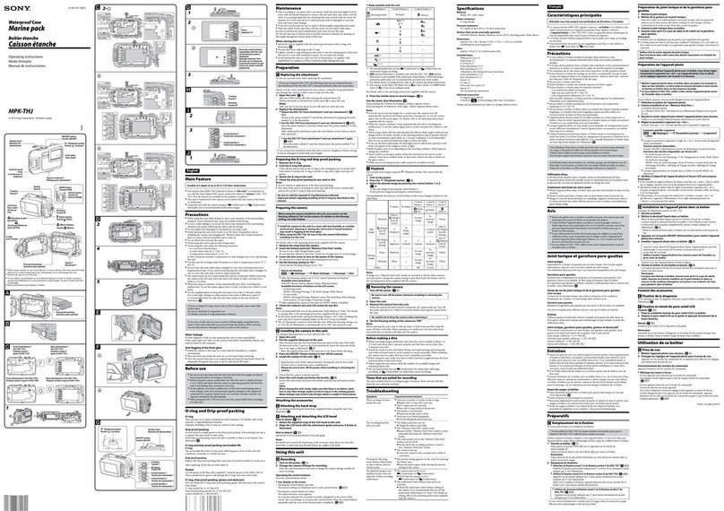
aNMI-LAN connectors (SFP+)
These connectors output IP video signals and audio. The
output signal format is the same as the format set for SLOT4.
Note Note
1

11
HKCU-4001 ST 2110 Interface Kit
(Option)
For safety, only a qualified technician with service training
should perform tasks inside the unit.
Connection with devices that are SMPTE ST 2110 compliant
is supported by installing an HKCU-4001 to the HDCU4300.
HDCU4300 software version 2.00 or later is required. An
OTM-10GSR1 or other SFP+ module or SFP28 module is
required to use IP output.
aLAN-1, LAN-2 connectors (SFP+/SFP28)
IP video signals and audio input/output, intercom, and network
synchronization are supported. This enables three IP outputs
and two IP inputs for HD signals on the HDCU4300.
For RCP/MSU device connection and IP tally input, use the
LAN-COM connector.
The input/output signal format is set using the <OUTPUT
FORMAT2> page and <RETURN> page in the setup menu.
HKCU-4002 12G-SDI Extension Kit
(Option)
For safety, only a qualified technician with service training
should perform tasks inside the unit.
The HDCU4300 supports 4K 2-system 12G-SDI output or
6G-SDI output by installing an HKCU-4002 in the HDCU4300.
HDCU4300 software version 1.50 or later is required.
For details about installation, contact a Sony service or sales
representative.
a12G/6G-SDI output connectors
These connectors are 12G-SDI output connectors or 6G-SDI
output connectors. The output format is the same as the
format set for SLOT1 of the HDCU4300.
For details, see page 37.
Note
Note
1
1

12
Connections and Settings
4K System Connection
A 4K format camera system is formed by connecting the unit
and a video camera (HDC4300 or HDC-P431)) with optical
fiber cables.
The functions provided by the unit (genlock, power supply to the
video camera, various interface functions, etc.) can be used as
is.
HD signals down-converted from 4K signals can be output
from SLOT2 and SLOT3.
1) Requires an HKCU-SM100 CCU Extension Adaptor and single-
mode fiber cable.
Connection example
Settings
INCOM
INTERCOM 1
PROD
LEVEL
REAR
FRONT
MIC
ON
OFF ENG
OFF
+48V
MIC
FRONT MIC
PROMPTER
/GEN
LOCK
RET CTRL
AUDIO IN
CH1 CH2
TEST
OUT
SDI
MONI
DC IN 10.5-17V
LINE
OFF
+48V
MIC
AES/EBU
LINE
INCOM
INTERCOM 2
EARPHONE REMOTE
DC OUT
CRANETRACKER
PROD
LEVEL
REAR
FRONT
MIC
ON
OFF ENG
LAN
SDI 1
SDI 2
SDI-MONI
RETURN SDI IN
1-2
REFERENCE
SDI I/O 1
SDI I/O 2
CAMERA
SDI OUT SDI OUT
SDI
OUT
1
SDI
OUT
3
SDI
OUT
5
SDI
OUT
7
SDI
OUT
2
SDI
OUT
4
SDI
OUT
6
SDI
OUT
8
HDC4300
HDCU4300
SDI Monitor/Prompter
(Digital)
Optical fiber cable
3G SDI/
HD SDI Monitor
LINK-1 LINK-2 LINK-3 LINK-4
Switcher
(4K-QUAD Link)
HD SDI Monitor
Monitor
(4K-QUAD Link)
HD PROMPTER signal
input
Reference signal input
Return signal input
Hub MSU-1000/1500
Master Setup Unit
RCP-3000/1000 series
Remote Control Panel
For details about the assignments of BNC connectors of the unit, see “Relationship between
Connection Type and BNC Connector Assignment” (page 17).
HD TRUNK signal input
HD TRUNK signal output
HD PROMPTER signal output
Device Purpose Menu/Page Item Set value
HDCU4300 HD system format setting SYSTEM OPERATION/<MULTI FORMAT> BASE FORMAT Set other than 3G-SDI
Video format setting SYSTEM OPERATION/<MULTI FORMAT> 4K/HFR FORMAT Video format
Video output format setting SYSTEM OPERATION/<OUTPUT
FORMAT>
SLOT1 to SLOT3 Video output format of
each slot
Assignment of function of SDI I/O
connector
MAINTENANCE/<I/F SETTINGS> SLOT3 (SDI I/O) SDI IN3/
HD PROMPTER IN,
HD TRUNK OUT
HDC4300 HD-PROMPTER output and HD
TRUNK input settings
MAINTENANCE/<SDI OUT> SDI-1 OUT HD PROMPTER
SDI-2 OUT/IN HD TRUNK/RET IN

13
HD CUTOUT Video System
An HD signal can be extracted from the 4K signal by installing
the optional SZC-2001/2001M/2001W HD CUTOUT Software
in the HDCU4300.
The region that is cut out can be controlled using a mouse or
other device connected to the HD CUTOUT Controller.
For details about setup and operation, refer to the SZC-2001/
2001M/2001W User’s Guide.
The cutout HD signal is output from SLOT1.
HD video down-converted from 4K signals can be output from
SLOT2, SLOT3, and SLOT4.
Also, a wire frame indicating the cutout region can be
displayed.
Connection example
Settings
Device Purpose Menu/Page Item Set value
HDCU4300 HD system format setting SYSTEM OPERATION/<MULTI FORMAT> BASE FORMAT Select 59.94 or 50
frequency format
Video format setting SYSTEM OPERATION/<MULTI FORMAT> 4K/HFR FORMAT Video format
Video output format setting SYSTEM OPERATION/<OUTPUT
FORMAT>
SLOT1 to SLOT4 Video output format of
each slot
HD CUTOUT settings SYSTEM OPERATION/<CHU MODE> CHU MODE HDC(HD CUTOUT)
SYSTEM OPERATION/<HD CUTOUT> HD CUTOUT ON (fixed)
HDC4300 HD-PROMPTER output and HD
TRUNK input settings
MAINTENANCE/<SDI OUT> SDI-1 OUT HD PROMPTER
SDI-2 OUT/IN HD TRUNK/RET IN
INCOM
INTERCOM 1
PROD
LEVEL
REAR
FRONT
MIC
ON
OFF ENG
OFF
+48V
MIC
FRONT MIC
PROMPTER
/GEN
LOCK
RET CTRL
AUDIO IN
CH1 CH2
TEST
OUT
SDI
MONI
DC IN 10.5-17V
LINE
OFF
+48V
MIC
AES/EBU
LINE
INCOM
INTERCOM 2
EARPHONE REMOTE
DC OUT
CRANETRACKER
PROD
LEVEL
REAR
FRONT
MIC
ON
OFF ENG
LAN
SDI 1
SDI 2
SDI-MONI
RETURN SDI IN
1-2
REFERENCE
SDI I/O 1
SDI I/O 2
CAMERA
SDI OUT SDI OUT
SDI
OUT
1
SDI
OUT
3
HDC4300
HDCU4300
SDI Monitor/Prompter
(Digital)
Optical fiber cable
3G SDI/
HD SDI Monitor
Switcher
(3G/HD SDI)
HD SDI Monitor
HD PROMPTER signal input
Reference signal input
Return signal input
Hub MSU-1000/1500
Master Setup Unit
RCP-3000/1000 series
Remote Control Panel
For details about the assignments of BNC connectors of the unit,
see “Relationship between Connection Type and BNC Connector
Assignment” (page 17).
HD TRUNK signal input
HD TRUNK signal output
HD PROMPTER signal output
HD
CUTOUT-1
HD
CUTOUT-2
CNA-1 Camera Control Network Adaptor
Mouse

14
HFR Video System
The unit can transfer HFR video and perform signal
processing for the following formats according to the
connected camera.
Yes: Supported, No: Not supported
1) Interlaced output is also supported in HD HFR 1080 format.
2) Selectable only when the format is set to 720P.
1x video can be output at the same time from SLOT2 and
SLOT3.
The HFR imaging function is dependent on the software
version of the connected camera. Check the compatibility of
each device before use.
HFR format Connected device
HDC4300, HDC-P43 (without option) HDC4300, HDC-P43
(when SZC-4002 series installed on the unit)
1080/59.94P (2x) 1) Yes Yes
1080/50P (2x) 1) Yes Yes
720/59.94P (2x) 2) Yes Yes
720/50P (2x) 2) Yes Yes
1080/59.94P (3x) 1) Yes Yes
1080/50P (3x) 1) Yes Yes
720/59.94P (3x) 2) Yes Yes
720/50P (3x) 2) Yes Yes
1080/59.94P (4x) 1) No Yes
1080/50P (4x) 1) No Yes
720/59.94P (4x) 2) No Yes
720/50P (4x) 2) No Yes
1080/59.94i (6x) 1) No Yes
1080/50i (6x) 1) No Yes
720/59.94P (6x) 2) No Yes
720/50P (6x) 2) No Yes
1080/59.94i (8x) 1) No Yes
1080/50i (8x) 1) No Yes
720/59.94P (8x) 2) No Yes
720/50P (8x) 2) No Yes
Note

15
Connection example (4x HD)
INCOM
INTERCOM 1
PROD
LEVEL
REAR
FRONT
MIC
ON
OFF ENG
OFF
+48V
MIC
FRONT MIC
PROMPTER
/GEN
LOCK
RET CTRL
AUDIO IN
CH1 CH2
TEST
OUT
SDI
MONI
DC IN 10.5-17V
LINE
OFF
+48V
MIC
AES/EBU
LINE
INCOM
INTERCOM 2
EARPHONE REMOTE
DC OUT
CRANETRACKER
PROD
LEVEL
REAR
FRONT
MIC
ON
OFF ENG
LAN
SDI-MONI
RETURN SDI IN
1-2
REFERENCE
SDI I/O 1
CAMERA
SDI OUT SDI OUT
SDI
OUT
1
SDI
OUT
3
SDI
OUT
5
SDI
OUT
7
SDI 1
HDC4300
HDCU4300
SDI Monitor/Prompter
(Digital)
Optical fiber cable
3G SDI/
HD SDI Monitor
LINK-1 LINK-2 LINK-3 LINK-4
Storage Unit
(PWS-4400, etc.)
HD SDI Monitor
HD PROMPTER signal
input
Reference signal input
Return signal input
Hub MSU-1000/1500
Master Setup Unit
RCP-3000/1000 series
Remote Control Panel
For details about the assignments of BNC connectors of the unit, see “Relationship between
Connection Type and BNC Connector Assignment” (page 17).
HD PROMPTER signal output

16
HDR Video System
When a 4K format camera system is selected, the dynamic
range of the camera can be enhanced to produce HDR video
output from SLOT1 by setting HDR MODE to Live HDR.
Set the HDR Look at the same time.
HDR/SDR or 4K/HD can be output from SLOT1.
The HD output from SLOT2, SLOT3, and SLOT4 is always
SDR video.
HDR Look
The HDR Look is a setting that determines the basic Look
(visual performance, attractiveness) of the HDR video.
This is a basic setting that determines how the image captured
by the camera will be displayed on the display as an HDR
image. You can select from the following three settings.
Live: Characteristics based on the traditional Look derived
from current SDR images. A powerful image with strong
contrast and high color density. Wide dynamic range with
substantial image brightness, capturing highlights without
overexposure.
Mild: Based on the Live setting but with an overall milder
image characteristic.
Natural: HLG original Look. Calm, gentle color density. The
actual sensitivity setting is reduced, but with better S/N
ratio. Natural can be selected only when the output signal
OETF setting is HLG.
Settings
INCOM
INTERCOM 1
PROD
LEVEL
REAR
FRONT
MIC
ON
OFF ENG
OFF
+48V
MIC
FRONT MIC
PROMPTER
/GEN
LOCK
RET CTRL
AUDIO IN
CH1 CH2
TEST
OUT
SDI
MONI
DC IN 10.5-17V
LINE
OFF
+48V
MIC
AES/EBU
LINE
INCOM
INTERCOM 2
EARPHONE REMOTE
DC OUT
CRANETRACKER
PROD
LEVEL
REAR
FRONT
MIC
ON
OFF ENG
LAN
SDI 1
SDI 2
SDI-MONI
RETURN SDI IN
1-2
REFERENCE
SDI I/O 1
SDI I/O 2
CAMERA
SDI OUT SDI OUT
SDI
OUT
1
SDI
OUT
3
SDI
OUT
5
SDI
OUT
7
SDI
OUT
2
SDI
OUT
4
SDI
OUT
6
SDI
OUT
8
HDC4300
HDCU4300
SDI Monitor/Prompter
(Digital)
Optical fiber cable
3G SDI/
HD SDI Monitor
LINK-1 LINK-2 LINK-3 LINK-4
HDR/SDR Output
4K/HD Output
HD SDI Monitor
Monitor
(4K-QUAD Link)
HD PROMPTER signal input
Reference signal input
Return signal input
Hub MSU-1000/1500
Master Setup Unit
RCP-3000/1000 series
Remote Control Panel
For details about the assignments of BNC connectors of the unit, see “Relationship between Connection Type
and BNC Connector Assignment” (page 17).
HD TRUNK signal input
HD TRUNK signal output
HD PROMPTER signal output
Device Purpose Menu/Page Item Set value
HDCU4300 Transfer to HDR mode SYSTEM OPERATION/<HDR> HDR MODE LIVE HDR (Live HDR video output)
SYSTEM OPERATION/<OUTPUT
FORMAT>
LOOK Live
Mild
Natural
SLOT1 OETF S-Log3 (SR Live recommended setting)
HLG (Compliant with HLG format)

17
Relationship between Connection Type and BNC Connector Assignment
The names of output interfaces in Table 1 correspond to
connector assignments in Table 2 (page 19). Check the output
interface for the format you want to use in Table 1, then check
the signal assignments to BNC connectors in Table 2.
Table 1: Relationship between operation mode/signal format and output interface
Operation
mode
Frame rate Slot1 Slot2/Slot3
Output format Output interface Output format
4K 59.94 4K/59.94P 3) Quad-Link-1 3G 1080/59.94P(3G), 1080/59.94i(1.5G), 720/59.94P(1.5G) 2),
525/59.94i
Single-Link 12G 5)
1080/59.94P 4) Single-Link 3G
1080/59.94i 4) 1.5G
50 4K/50P 3) Quad-Link-1 3G 1080/50P(3G), 1080/50i(1.5G), 720/50P(1.5G) 2), 625/50i
Single-Link 12G
1080/50P 4) Single-Link 3G
1080/50i 4) 1.5G
29.97 4K/29.97P 1) 3) Dual-Link-2 3G 1080/29.97PsF(1.5G), 525/29.97PsF
Single-Link 6G 5)
4K/29.97PsF 1) 3) Dual-Link-2 3G
Quad-Link-1 1.5G
1080/29.97PsF 4) Single-Link
25 4K/25P 1) 3) Dual-Link-2 3G 1080/25PsF(1.5G), 625/25PsF
Single-Link 6G 5)
4K/25PsF 1) 3) Dual-Link-2 3G
Quad-Link-1 1.5G
1080/25PsF 4) Single-Link
24 4K/24P 1) 3) Dual-Link-2 3G 1080/24PsF(1.5G), 1080/50i(1.5G), 625/50i
Single-Link 6G 5)
4K/24PsF 1) 3) Dual-Link-2 3G
Quad-Link-1 1.5G
1080/24PsF 4) Single-Link
23.98 4K/23.98P 1) 3) Dual-Link-2 3G 1080/23.98PsF(1.5G), 1080/59.94i(1.5G), 525/59.94i
Single-Link 6G 5)
4K/23.98PsF 1) 3) Dual-Link-2 3G
Quad-Link-1 1.5G
1080/23.98PsF 4) Single-Link

18
1) Output is P when the division method is 2SI, and PsF when the division method is SQD.
2) Output only when the BASE FORMAT is 720P.
3) A Slot1 output format of “4K” refers to 4096x2160 or 3840x2160.
4) Supported when the BASE FORMAT is 1080.
5) Supported when HKCU-4002 is installed.
HD HFR 59.94(8x) 1080/59.94i(8x),
720/59.94P(8x) 2) Quad-Link-2 3G 1080/59.94i(1.5G), 720/59.94P(1.5G) 2), 525/59.94i
50(8x) 1080/50i(8x),
720/50P(8x) 2) Quad-Link-2 3G 1080/50i(1.5G), 720/50P(1.5G) 2), 625/50i
59.94(6x) 1080/59.94i(6x),
720/59.94P(6x) 2) Triple-Link-2 3G 1080/59.94i(1.5G), 720/59.94P(1.5G) 2), 525/59.94i
50(6x) 1080/50i(6x),
720/50P(6x) 2) Triple-Link-2 3G 1080/50i(1.5G), 720/50P(1.5G) 2), 625/50i
59.94(4x) 1080/59.94P(4x) Quad-Link-1 3G 1080/59.94P(3G), 1080/59.94i(1.5G), 720/59.94P(1.5G) 2),
525/59.94i
1080/59.94i(4x),
720/59.94P(4x) 2) 1.5G
Dual-Link-2 3G
50(4x) 1080/50P(4x) Quad-Link-1 3G 1080/50P(3G), 1080/50i(1.5G), 720/50P(1.5G) 2), 625/50i
1080/50i(4x),
720/50P(4x) 2) 1.5G
Dual-Link-2 3G
59.94(3x) 1080/59.94P(3x) Triple-Link-1 3G 1080/59.94P(3G), 1080/59.94i(1.5G), 720/59.94P(1.5G) 2),
525/59.94i
1080/59.94i(3x),
720/59.94P(3x) 2) 1.5G
50(3x) 1080/50P(3x) Triple-Link-1 3G 1080/50P(3G), 1080/50i(1.5G), 720/50P(1.5G) 2), 625/50i
1080/50i(3x),
720/50P(3x) 2) 1.5G
59.94(2x) 1080/59.94P(2x) Dual-Link-1 3G 1080/59.94P(3G), 1080/59.94i(1.5G), 720/59.94P(1.5G) 2),
525/59.94i
1080/59.94i(2x),
720/59.94P(2x) 2) 1.5G
Single-Link 3G
50(2x) 1080/50P(2x) Dual-Link-1 3G 1080/50P(3G), 1080/50i(1.5G), 720/50P(1.5G) 2), 625/50i
1080/50i(2x),
720/50P(2x) 2) 1.5G
Single-Link 3G
HD CUTOUT 59.94 1080/59.94P 4) Single-Link 3G 1080/59.94P(3G), 1080/59.94i(1.5G), 720/59.94P(1.5G) 2),
525/59.94i
1080/59.94i 4) 1.5G
720/59.94P 2)
50 1080/50P 4) Single-Link 3G 1080/50P(3G), 1080/50i(1.5G), 720/50P(1.5G) 2), 625/50i
1080/50i 4) 1.5G
720/50P 2)
Operation
mode
Frame rate Slot1 Slot2/Slot3
Output format Output interface Output format

19
Figure 1: Slot numbers and BNC connectors
Table 2: Relationship between output interface and BNC connector assignment
a) SDI OUT 1 and SDI OUT 2 output the same data.
b) SDI OUT 3 and SDI OUT 4 output the same data.
c) SDI OUT 5 and SDI OUT 6 output the same data.
d) SDI OUT 7 and SDI OUT 8 output the same data.
Paint Functions in HDR MODE and COLOR SPACE
Some paint functions are disabled, depending on the HDR
MODE and COLOR SPACE settings on the HDCU4300.
Disabled items can still be adjusted from the PAINT menu on
the camera or RCP/MSU, but the settings are not applied to
the HDR video that is output from SLOT1.
Paint functions that can be adjusted when HDR MODE is selected
MAIN Output 4K / HD HFR/HD CUTOUT
SLOT 1
Operation mode Output interface
SDI OUT 1-2
a)
SDI OUT 3-4
b)
SDI OUT 5- 6
c)
SDI OUT 7- 8
d)
4K Quad-Link-1 Link-1 Link-2 Link-3 Link-4
Dual-Link-1 Link-1 Link-2 Link-1 Link-2
HD HFR Quad-Link-1 Link-1 Link-2 Link-3 Link-4
Quad-Link-2 Link-1/2 Link-3/4 Link-5/6 Link-7/8
Triple-Link-1 Link-1 Link-2 Link-3 (Link-2)
Triple-Link-2 Link-1/2 Link-3/4 Link-5/6 (Link-3/4)
Dual-Link-1 Link-1 Link-2 Link-1 Link-2
Dual-Link-2 Link-1/2 Link-3/4 Link-1/2 Link-3/4
Single-Link Link-1/2 Link-1/2 Link-1/2 Link-1/2
HD CUTOUT
Perspective CUTOUT CUTOUT CUTOUT CUTOUT
Simple HD CUTOUT1 CUTOUT2 CUTOUT1 CUTOUT2
SLOT1
SLOT3 SLOT2
Paint function HDR MODE setting
OFF LIVE HDR
Gain Step Gain Yes Yes
Master White Gain Yes Yes
White R/G/B Yes Yes
Balance/C Temp Yes Yes

20
Gamma ON/OFF Yes (Fixed OETF)
R/G/B/Master Yes No
Step Gamma Yes No
Black R/G/B/Master Yes Yes
Black Gamma ON/OFF Yes Yes
Range Yes Yes
R/G/B/Master Yes Yes
Flare ON/OFF Yes Yes
R/G/B/Master Yes Yes
Knee ON/OFF Yes (Fixed OFF)
Knee Point R/G/B/Master Yes No
Knee Slope R/G/B/Master Yes No
Auto Knee ON/OFF Yes No
Auto Knee Point Limit Yes No
Auto Knee Auto Slope Yes No
Detail ON/OFF Yes Yes
Level Yes Yes
Limiter Yes Yes
Crispening Yes Yes
Level Dep Yes Yes
H/V Ratio Yes Yes
Frequency Yes Yes
Mix Ratio Yes No
W.Limiter Yes Yes
B.Limiter Yes Yes
Knee Apt ON/OFF Yes (Fixed OFF)
Knee Apt Level Yes No
Shutter Shutter ON/OFF Yes Yes
ECS ON/OFF Yes Yes
Shutter Level Yes Yes
ECS Level Yes Yes
Skin Detail ON/OFF Yes Yes
Gate ON/OFF Yes No
Zoom Link ON/OFF Yes Yes
Natural Skin DTL ON/OFF Yes Yes
Level Yes Yes
Phase Yes Yes
Width Yes Yes
Saturation Yes Yes
Y Limit Yes Yes
Saturation ON/OFF Yes Yes
Saturation Yes Yes
Paint function HDR MODE setting
OFF LIVE HDR
This manual suits for next models
3
Table of contents
Other Sony Camera Accessories manuals

Sony
Sony CA4000 User manual

Sony
Sony NP-F330 Operating Instructions (primary... Service manual

Sony
Sony MPK-URX100A User manual

Sony
Sony DXF-C50WA User manual

Sony
Sony SPK-TRC User manual

Sony
Sony FCB-CX45CP User manual

Sony
Sony UNI-PMA1 User manual

Sony
Sony MPK-F40 User manual

Sony
Sony MPK-WG User manual

Sony
Sony VG-C77AM User manual
Popular Camera Accessories manuals by other brands

Active Silicon
Active Silicon Harrier 36 Series Technical reference manual

DreamGEAR
DreamGEAR Power Bricks user guide

Panasonic
Panasonic Lumix H-ES045 operating instructions

Phase Trigger
Phase Trigger Event 5.6 operating instructions

Pentax
Pentax Tele Converter TE-Z100 operating manual

Westfalia
Westfalia 817033 instructions