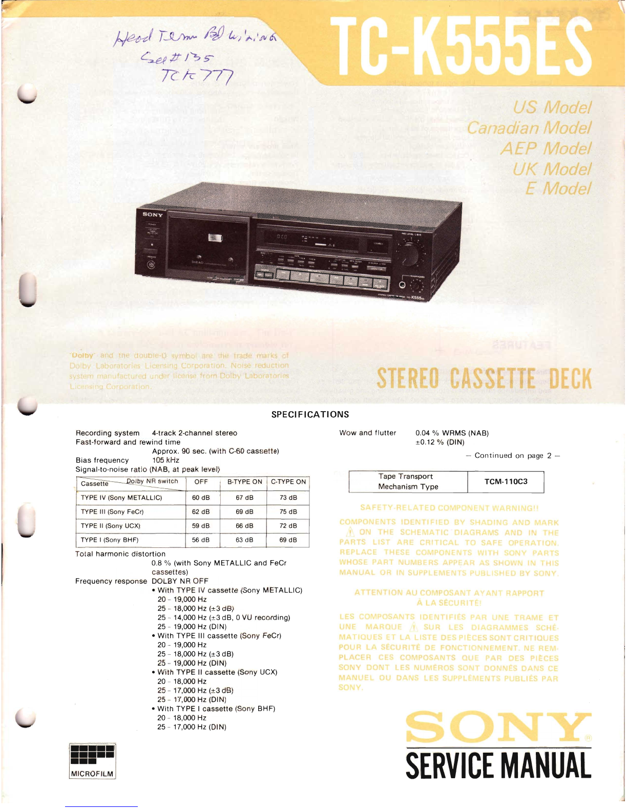
Sony TC-K555ES User manual

~T
~~~#
I'?s--
R
k7
77
E
SPECIFICATIONS
TCM-110C3
-
Continued
on page 2 -
0.04 %
WRMS
(NAB)
±0.12 %
(D
IN)
SERVICE
MANUAL
Tape
Transport
Mechanism
Type
Wow
and
fl
utter
ChOFF B-TYPE ON C-TYPE ON
TYPE IV (Sony METALLIC) 60
dB
67
dB
73
dB
TYPE III (Sony FeCr) 62
dB
69
dB
75
dB
TYPE
II
(Sony UCX)
59
dB
66
dB
72
dB
TYPE I(Sony BH
F)
56
dB
63
dB
69
dB
Recording
system
4-track
2-channel
stereo
Fast-forward
and
rewind
time
Approx.
90 sec.
(with
C-60
cassette)
Bias
frequency
105
kHz
Signal-to-noise
ratio
(NAB,
at
peak
level)
Total
harmonic
distortion
0.8 %
(with
Sony
METALLIC
and
FeCr
cassettes)
Frequency
response
DOLBY
NR
OFF
•
With
TYPE IV
cassette
(Sony
METALLIC)
20 -19,000 Hz
25 -18,000 Hz (±3 dB)
25 -14,000 Hz (±3 dB, °
VU
recording)
25 -19,000 Hz (DIN)
•
With
TYPE"
I
cassette
(Sony FeCr)
20 -19,000 Hz
25 -18,000 Hz
(±3
dB)
25 -19,000 Hz (DIN)
•
With
TYPE"
cassette
(Sony UCX)
20 -18,000 Hz
25 -17,000 Hz
(±3
dB)
25 -17,000 Hz (DIN)
•
With
TYPE I
cassette
(Sony BH
F)
20 -18,000 Hz
25 -17,000 Hz (DIN)
•••••
•••••
•••
MICROFILM

TC-K555ES
I
OdB=O.775V
I
Peak
program
meters
Response range
-40
dB
to
+8dB
Frequency
response
20
-20,000
Hz
zl.5
dB
Response
time
1
millisecond
Decay
time
(from
0
dB
to
-20
dB)
750
milliseconds
Overshoot
none
r-
------
--
Inputs
Line
inputs
(phono
jacks)
Sensitivity
77.5
mV
(-20
dB)
Input
impedance
50
k
ohms
Outputs
Line
outputs
(phono
jacks)
Output
level 0.435 V
(-5
dB)
at
aload
impedance
of
50 k
ohms
Load
impedance
over 10 k
ohms
Headphone
output
Output
level,
variable
from
-20
dB
to
-50
dB
at
a
load
impedance
of
8
ohms
General
Power
requirements
AEP
model:
220
Vac,
50/60
Hz
(240V
ac adjustable
by
authorized
Sony
personnel)
UK
model:
240V
ac,
50/60
Hz
(220
Vac adjustable
by
authorized
Sony
personnel)
US, Canadian
model:
120
Vac,
60
Hz
E
model:
110,
120,220
or
240
Vac ad-
justable,
50/60
Hz
FEATURES
Power
consumption
Dimensions
Weight
26
watts
Approx. 430 x105 x285
mm
(w/h/d)
(17
x4'/. x11'/. inches)
inclUding
projecting
parts
and
controls
Approx.
6.1
kg
(13
Ibs
80z)
Three-head
system
Separate record and
playback
heads
allow
optimum
gap
settings
and
impedance
ratings
for
distortion-free
recording
and
greatly
ex-
tended
frequency
response. For
good
tape·to-head
contact
the
heads
are
mounted
in one
block
and each head is
separately
ad-
justed
for precise
azimuth
alignment.
The three-head
system
also
enables
you
to
monitor
the
recorded
tape
while
actually
recording.
Newly-developed LA
(LaserAmorphous)
head
The
record/playback
head is
made
of
a
special
amorphous
magnetic
alloy
developed by Sony, and
its
cores
are
solidly
welded
by laser. This new
highly-durable
head provides a
wider
dynamic
range and a
more
extended
frequency
response,
especially
in the
high-frequency
range. The head is designed
to
take
full
advantage
of
the
potential
of
the
metal
tapes.
Closed-loop
dual-capstan
tape
drive
system
Two
pairs
of
capstans
and
pinch
rollers
ensure
uniform
tape
ten-
sion
and
stable
tape-to-head
contact.
As aresult,
wow
and
flutter
and
modulation
noise
are
greatly
reduced.
Dolby
C-type NR (noise
reduction)
system
In
addition
to
the
conventional
B-type Dolby NR system,
this
cassette
deck
employs
the
newly-developed C-type
Dolby
NR
system
which reduces
tape
noise
twice
as
effectively
as the B-type
system. The C-type
system
also
incorporates
an
anti-saturation
network
to
improve
the
high-frequency
dynamic
range by 4
dB
at
10
kHz.
Digital
linear
counter
This
counter
indicates
the
recording
or
playback
time
elapsed on
the tape so
that
the
tape
can be precisely indexed.
While
conven-
tional
displays
can
only
indicate
the elapsed
recording
time,
this
display
can
indicate
with
a
minus
sign
how
much
recording
time
re-
mains.
Bright
FL-display peak
program
meters
The peak
program
meters
follow
the
transient
peaks
of
the
music
and
maintain
the peak
readings
for
about
4seconds.
This
double
indication
makes
it easy
to
set
critical
recording
levels precisely.
Remote
control
operation
Using
the
optional
RM-50
or
RM-80
remote
control
unit,
various
operations-recording,
playback,
record
muting
operation,
etc.-
can be
remotely
controlled.
When the RM-65
synchro
remote
control
unit
is used
to
connect
this
cassette
deck
with
a
turntable
equipped
with
a
synchro
remote
control
jack, the
operation
of
the
cassette
deck
and the
turntable
will be synchronized.
Two
motors
The
two-motor
drive
system
assures
accurate
and
stable
tape
transport.
The
capstan
is driven by alinear
torque
BSL (brush/ess
and
slot
less)
motor
to
keep
wow
and
flutter
low
and
to
provide
smooth
torque.
Useful
functions
.Record
muting
function
allows
you
to
easily
insert a
moderately
long
blank
space
between
selections.
.Auto
play
permits
one
step
rewind and
playback
from
the begin-
ning
of
the
tape
and
the
memory
function
allows
you
to
easily
locate
any desired
point
on the tape.
.A
timer
switch
is provided
to
turn the
deck
on and
off
any
number
of
times
at preset
times
set on an
optional
timer.
-2-

SAFETY
CHECK-OUT
(US Model)
After
correcting
the
original service
problem,
perform
the
following safety
check
before
releasing
the
set
to
the
customer:
Check
the
antenna
terminals,
metal
trim,
"metallized"
knobs,
screws,
and
all
other
exposed
metal
parts
for
AC leakage.
Check
leakage as described below.
LEAKAGE
TEST
TC-K555ES
3. Measuring the voltage
drop
across
aresistor by
means
of
aYOM
or
battery-operated
AC
volt-
meter.
The
"limit"
indication
is
0.75
V,
so
analog
meters
must have an
accurate
low-
voltage scale.
The
Simpson
250
and Sanwa
SH-63Trd are
examples
of
apassive YOM
that
is suitable. Nearly all
battery
operated
digital
multimeters
that
have a 2V
AC
range are
suitable. (See Fig. A)
The
AC leakage from
any
exposed
metal
part
to
earth
ground
and
from all exposed metal
parts
to
any
exposed
metal
part
having a
return
to chassis,
must
not
exceed
0.5 rnA
(500
microampers).
Leakage
current
can be measured by
anyone
of
three
methods.
I.
A
commercial
leakage tester,
such
as
the
Simpson 229
or
RCA WT-540A.
Follow
the
manufacturers'
instructions
to
use
these
instru-
ments.
2. A
battery-operated
AC milliammeter.
The
Data
Precision 245 digital
multimeter
is
suitable for
this
job.
To
Exposed
Metal
Parts
on
Set
1.5kH
..L Earth
Ground
AC
voltmeter
(0.75
V)
MODEL
IDENTIFICATION
-
Specification
Label
-
SON~
MODEL
NO. TC-K555ES
TAPECORDER
SERIAL
NO.
MADE
IN
JAPAN
US,
Canadian model: AC 120 V60
Hz
26 W
Fig. A. Using an
AC
voltmeter
to check
AC
leakage.
SON~
MODEL
NO.
TC-K555ES
TAPECORDER
SERIAL
NO.
MADE
IN
JAPAN
AEP model: AC 220 V~50/60
Hz
26 W
UK
model: AC 240 V
~
50/60
Hz
26 W
Emodel: AC 110, 120, 220, 240 V
~
50/60
Hz
26 W
-3-

f~-K555ES
I,L
Caution
on
DOLBY
IC (CX174) Replacement
This set uses eight Dolby ICs
(CXI74).
(lCIOI,
102,201,202,301,302,401,402)
These
ICs
are
either
CX 174-1
or
CX-174-3.
When replacing these ICs, be sure
to
use
the
same
ICs as
the
original
one.
SONY
174 -
1
:CX174·1
3
:CX174-3
-4-

*
1-1. BLOCK
DIAGRAMS
-
Amp
Section -
-
L-CH--
PB
EO
AMP
IC501
SECTION 1
OUTLINE
TC-K555ES
5505-1 5506-2
I
DOLBY
NR
11Kl-----.I--+-~--+--___......___<:::I1
I
DOLBY
NRI
OFF
B
TYPE
• +
ON
C
TYPE
B+
(9.6Vl
TC-KS
TO
5Y5TEM
CONTROL
BOARD
CNJ301
I
L1Ni
INI
--
R-CH-
•
SAME
AS
L-CH
5507-1
I
MPX
FILTERI
OFF
+
ON
1Jc:}------~
SWITCHIREC
EO)
t------1I---------+__---_+----+----
0314
5506-1 5505-2
IDOLBY
NRI
IDOLBY
NR!
1J<}---+-"-+-~"""-----1t>f1
OFF
t
OFF
5504-2
:
j:::
O~
TO
MmR
.......
t---_-+--~I
O*N
TJlT~['
BOARD(Al@_,--t-----+--i>°FF5503-2
_ *
TYPE
ill
ON
Fe-Cr
-5-

.I
TC-K555ES I
S508-3
I
MONITOR
I
TAPE
+
SOURCE
HEADPHONE
AMP
~AA
CNJ501
IC503
r-~'"
Ir
IHEADPHONESI
R-CH
}
TO
SYSTEM
CONTROL
BOARD
~~
..
@
TO
METER
BOARD(A)
IC801
CNJ302
I
L1NE
L
OUT
I
RV302
METER
LEVEL
L
~...
~@
6)
,
R-CH
SWITCHING
Q514,515
S508-1
IMONITORI
TAPE
,
SOURCE
y
L~G31~MP
~.+
+
R-CH
METER
BOARD
(A)
ICBOI
OFF
t
ON
TO
SYSTEM
CONTROL
BOARD
8+
--1
VOL
..
REG.
H
VOL.REG.
~~
(9.6VlQ
502
-
504
Q50I
~~
B-
(-9.6Vl
PL501
PL502
B-
(9.6V)
B+
TO
SYSTEM
CONTROL
BOARD
RV502~1
IBIAsl
t~
¥v3T~M
CONTROL
BOARD
...
4-1
~~~~I
~
I
S504-2
,
,TYPE
N
'"'\
METAL
S503-2
t
ITYPE
ill
~\
Fe-Cr
-6-

TC-K555ES
-System Control Section -
SWITCH
-PM2~
~'
.~
~
TO
RECORD
BOARD
5802
ACCIDENTAL
ON
ERASURE
t
PREVENTION
OFF
0638
580 I
r----+-+---f-----t--+--+-~-+__t____1--~
CASSETE
HALF
OET
ON
t
OFF
~
~F
A
TO
RECORD
BOARD
@
0701
•
0702
~
0703
II
IC601
@I-----t
TO
SYSTEM
CONTROL
BOARD
~
I
FI
I
-7-
I

i55ES
TC-K555ES
TO
RECORD
BOARD
l~~
e
@
4)
~~
,-----o~
AC
IN
DOLBY
C
INDICATOR
0607,609
DOLBY
B
INDICATOR
0608,610
) •
~}
TO
RECORD
BOARD
1,2
AC
5.2V
r-----"------,
t
B+
B+
(6V)
(22VI
-
B+
(6V)
FLUORESCENT
DISPLAY
TUBE
B-t
B+ B+
(26VI (22VI
(~0)
,@
"TO
SERVO
BOARD
I I
B+
'i
(26V)
PLI
SPEED-DET
~~
0905,906
~
B-
(-203VI'
TO
PLAYBACK
BOARD
~.
•
(POWER
RESET)
5708
IRESETI
S709
[MEMORYI
0611
'4
~
1
TO
RECORD
BOARD
1I
SWITCH
I .
4.T~
f
LJL-~----________=_~-----
~~~,
~
B+
(15V)
0612,613
~~MI
~
-----.r
REEL
MOTOR
~
r\7I
PM2
~AMSSOLENOID
~~"\
PMI
~
HEAD
SOLENOID
;~G
-.~
~
,=-
-------------iIJl
'Xl
•I
IC604 (1/2)
-8-

TC-K555ES
1-2. FUNCTION OF CONTROLS
The
numbers
in
the
photo
are keyed
to
the
following
explanations.
TC-K5
COUNTER MEMORY
button
TAPE
select
buttons
and BIAS
control
e
Cassette
holder
TIMER
switch
•
REMOTE
control
connector
oPeak
program
meters
oDOLBY NR
switches
oMPX FILTER
switch
8
MONITOR
switch
and
indicator
REC LEVEL
(recording
level)
controls
•
HEADPHONES
level
control
•
Function
buttons
OPOWER
switch
Depress
this
switch
to
turn
on
the
power. The
lamp
in
the
cassette
holder,
the
display
of
the
peak
program
meter
and
the
tape
counter
will
light
up. The
indicator
lamp
of
the
pause
button
will
blink
for
about
4seconds,
indicating
that
the
function
buttons
are in-
operative
during
this
period.
Press
this
switch
again
to
turn
the
power
off.
•
~
(eject)
button
Press
this
button
to
open
the
cassette
holder.
eTAPE
select
buttons
and BIAS
control
Depress one
of
the
TAPE
select
buttons
according
to
the
type
of
tape
to
be used. When
the
appropriate
button
is depressed,
the
op-
timum
equalization
and
bias
current
settings
are
obtained
for
recording, and
the
optimum
equalization
setting
is
obtained
for
playback. When
recording
using
aTYPE I(NORM), TYPE
II
(Cr0
2)or
TYPE III (Fe-Cr) tape,
adjust
the
BIAS
control.
See
"Recommended
settings
for
the
TAPE
select
buttons
and
the
BIAS
control':
on
page
11.
.Peak
program meters
With
the
MONITOR
switch
set
to
SOURCE,
the
meters
show
the
peak
input
level
of
each channel, and
to
TAPE,
the
meters
show
recorded levels. They
follow
the
transient
peaks
of
high-level
inputs
that
are
too
brief
to
be
followed
by
conventional
VU
meters
so
that
the
optimum
recording
level can be
accurately
set. The
highest
in-
put
of
each
channel
is held
about
4
seconds
on
the
scale,
except
when a
higher
peak
occurs
before
4
seconds
have passed, in
which
case
that
peak is
immediately
indicated.
-9-
GOOLBY
NR
switches
The
left
switch
turns
the
Dolby
NR
*(Noise Reduction)
system
on
and
off
and
the
right
switch
selects
either
the
B-type
or
C-type
Dolby NR system.
To record
with
the
Dolby NR process, depress
the
ON/OFF
switch
to
the
ON
position
and
choose
B-TYPE
(n
)or C-TYPE
(.D.
).
To record
without
the
Dolby NR process, press
the
ON/OFF
switch
again
to
release.
When
playing
back, set
these
switches
to
the
same
position
used
in recording.
*
"Dolby"
and
the
double-D
symbol
are
trade
marks
of
the
Dolby
Laboratories
Licensing
Corporation.
Noise
reduction
system
manufactured
under
license
from
Dolby
Laboratories
Licensing
Corporation.
OMPX
FILTER
switch
Normally
set
this
switch
to
OFF.
When recording FM stereo
broadcasts
with
the
Dolby NR system,
set it
to
ON
if
the
19
kHz
pilot
signal
and
the
38
kHz
subcarrier
have
not
been
adequately
suppressed by
the
FM
tuner
or
receiver.
If
the
tuner
or
the
receiver
suppresses
such
signals
adequately
(most
high-quality
tuners
and receivers will), you
do
not
have
to
set
this
switch
to
ON.
•MONITOR
switch
and
indicator
When
adjusting
the
recording level, set
this
switch
to
the
released
position
(SOURCE
n)
to
allow
monitoring
of
the
sound
to
be
recorded. During
playback,
depress
this
switch
(TAPE
0.)
to
allow
monitoring
of
the
recorded sound.
According
to
the
MONITOR
switch
setting,
"SOURCE"
or
"TAPE"
will
appear in
the
indicator
window.
During recording, use
this
switch
to
monitor
either
the
source
or
the
recorded sound.

TC-K555ES
OREC
LEVEL (recording level) controls
These
controls
adjust
the
recording level. The
knob
nearest
the
panel is for the
left
channel and the
other
knob
for
the
right
chan-
nel. To
adjust
the level
of
the
left
or right channel only,
turn
the ap-
propriate
knob
while
holding
the
other
knob.
OTiMER
switch
You can set
the
unit
to
record or play back at apredetermined
time
by
connecting
any
commercially
available timer. To record, set
this
timer
switch
to
REC.
To play back, set it
to
PLAY.
(!) REMOTE control connector
Connect
the
optional
RM-50 (wired) or RM-80 (wireless) remote con-
trol
unit
to
operate
the
tape
transport
functions
from a
distance.
Synchronized
operation
is
also
possible
with
selected Sony turn-
tables, using
the
optional
RM-65
synchro
remote
control
unit. Read
the
instruction
manual
of
your
remote
control
unit
before
operating
it.
CD
Tape counter
This
counter
indicates
the
tape
running
time
.
•COUNTER RESET button
Press
this
button
to
reset
the
tape
counter
to
"0.00."
GCOUNTER
MEMORY button
Press
to
rewind the tape
to
the
"0.00"
point
on
the
tape counter.
The word
"MEMORY"
is
displayed
below
the
tape
counter. Press-
ing the
~
button
together
with
the -
button
automatically
starts
playback
from
"0.00."
When you
do
not use the
memory
function,
press
this
button
again.
The word
"MEMORY"
will disappear.
4D
Function buttons
It is possible
to
switch
directly
from one mode
to
another. The in-
dicator
lamps
light
when
the
tape
deck
is
in
the
forward, record or
pause mode.
-(rewind)
button:
Press
this
button
to
rewind
the
tape. This
button
is
also
used,
with
the
~
button,
to
initiate
auto
play.
•(stop)
button:
To
stop
the tape, press
this
button.
The tape will
stop
automatically
when it is
completely
wound in
either
direc-
tion.
~
(forward)
button:
Press
this
button
to
play
the
tape back. To
record, press
this
button
while
holding
the.
button
down.
-(fast-forward)
button:
Press
this
button
to
advance
the
tape
rapidly.
•(record)
button:
Press
this
button
together
with
the
~
button
to
start
recording.
"(pause)
button:
To pause
for
a
moment
during
recording or
playback, press
this
button.
This
button
is also used
to
control
more precisely the
start
of
recording and
to
release
the
record
muting
mode.
o(record
muting)
button:
Press
this
button
to
eliminate
un-
wanted
material
and
to
insert a
blank
space
during
recording.
G)HEADPHONES jack
Headphones
may
be
inserted
either
to
monitor
the
input
signals
to
be recorded or
to
listen
to
arecording in the
playback
mode.
Headphone volume is
adjustable
with
the
HEADPHONES
control.
oHEADPHONES level control
This
control
adjusts
the
headphone level.
This
selling
does
not
af-
fect
the
peak program meters or the
output
level
of
the
LINE OUT
jacks
at
the
rear.
"
-10-

TC-K555ES
'-3.
RECORDING
RECOMMENDED SETTINGS FOR THE TAPE SELECT BUTTONS
AND BIAS CONTROL
Press
the
appropriate
TAPE
select
button
referring
to
the
recom-
mended
settings
listed
below. When recording using aTYPE I(nor-
mal), TYPE
II
(CrO,)
or
TYPE III (Fe-Cr) tape,
adjust
the
BIAS
control
also.
While
the
settings
are
optimum
for
Sony
cassettes,
you may
want
to
change
them when
using
cassettes
produced by
other
manufac-
tures.
BIAS
control
This
control
regulates bias current for TYPE I (NORM), TYPE
II
(CrO,) and TYPE III (Fe-Cr)
cassettes.
The full
counterclockwise
position
decreases bias by
about
20% from
the
center
position
and
the
full
clockwise
position
increases
it by
about
20%.
Generally, as
bias
is increased, extreme
high
frequencies
will
be suppressed. As
bias
is reduced,
extreme
high
frequencies
will
be boosted. You can
then
find
the
appropriate
bias
setting
for each brand
of
TYPE
I,
TYPE
II
and TYPE III
cassettes.
Tape
list
(for
Canada)
Tapes
(C-60
and
C·9O)
Type
01
tape
SONY:
LNX,
SHF
AMPEX:
GRAND
MASTER I
MAXELL:
UD, UD·XL
I,
FUJI:
FX·I TYPE I
XL I·S
MEMOREX:
MRX·'
(NORMAL)
SCOTCH:
MASTER I
TDK:
AD, AD·X
SONY:
UCX·S, EHF
AMPEX:
GRAND
MASTER
II
FUJI:
FX·II TYPE
II
MAXELL:
UD·XL II, XLlI·S
MEMOREX:
HIGH BIAS
II
(CrO,)
SCOTCH:
MASTER
II
TDK:
SA, SA·X
SONY:
FeCr
BASF:
PROFESSIONAL III TYPE III
SCOTCH:
MASTER III (Fe·Cr)
TYPE I
SONY:
METALLIC
Other
metal
tapes
(METAL)
CD
"0
.~
Qi
Bias
reduced
~
1---B-ia-s-I-'n-c-re-a-s-ed--ooE::----
"5
c.
"5
0'--
-::-
__
--:-,--
_
Frequency
in
Hz
RECORD MONITORING
As
this
tape
deck
has separate record and
playback
heads, you can
easily
compare
the source and the recorded
sounds
in
the
record-
ing mode by using
the
MONITOR
switch.
You can
check
the
record·
ing level and
whether
there
is
any
contamination
on the heads
that
is
affecting
the recording.
.If
the
connected
amplifier
has atape
monitor
selector,
sourcel
tape
comparison
is
possible
with
the
amplifier
monitor
selector. In
this
case, set
the
tape
deck
MO ITOR
switch
to
TAPE.
Tape
list
(for
other
countries)
MONITOR
switch
setting
and
signal
flow
REC LEVEL
l+---toJ
LINE IN
l+---toJ
LINE IN
REC LEVEL
Playback
head
J-J()~A~~~i~
~,,~
J;:==='h-
....
--Q~
MONITOR
TAPE
TO RECORD MATERIAL ONTO ASPECIFIC PORTION OF TAPE
When you want
to
re-record a
specific
portion
of
tape or
to
insert
new
material
between
two
points
on atape you will find it
handy
to
be able
to
change
directly
from
the
playback
to
the record mode by
pressing
the.
REC
button
while
holding
the
~
button
down.
The three-head
system
permits
you
to
monitor
the
recorded sound
while
in
the
record mode, so
that
you can easily
check
the
effects
of
various
settings
of
the
TAPE select
buttons
and the BIAS con-
trol.
f
Tapes (C-60
and
C·90)
Type
of
tape
SONY:
AHF,
BHF
AGFA:
SUPER FERRO
DYNAMIC
BASF:
LH-X.
Professional
I
FUJI:
FX·I TYPE I
MAX
ELL :UD, UD·XL
I,
XL I·S
PHILIPS:
SUPER FERRO·f (NORMAL)
SCOTCH:
MASTER I
TDK:
AD
SONY:
UCX·S, UCX
AGFA:
STEREO
CHROM
BASF:
Professional
II
FUJI:
FX·II TYPE
II
MAX
ELL
:UD·XLlI, XLlI·S
PHILIPS:
CHROMIUM
(CrO,)
SCOTCH:
MASTER
II
TDK:
SA, SA·X
SONY:
Feer
AGFA:
CARAT
TYPE III
BASF:
Professional III
PHILIPS:
FERRO
CHROMIUM
SCOTCH:
MASTER III (Fe·Cr)
TYPE IV
SONY:
METALLIC
Other
metal
tapes
(METAL)
-11-

PM
1M
'M
HE
)
R
G
El
9
TC-K555ES
1-4. TO ADJUST THE
RECORDING
LEVEL
Adjust
the
recording
level
while
monitoring
on
the
peak
program
meters
the
input
level
of
the
program
source
to
be recorded.
If
the
recording
level
setting
is
too
high,
the
recording
will
be
distorted,
and
if
the
setting
is
too
low,
the
recording
will
be
noisy.
The record·
ing level
should
be set as
high
as
possible
while
still
avoiding
distortion.
This
level
will
depend
on
the
type
of
tape
being
used.
When
the
TAPE
button
is
pressed,
the
range
above
the
saturation
level
of
the
selected
type
of
tape
is
indicated
by
the
red line.
Generally
speaking,
adjust
the
recording
level
by
making
sure
that
the
meters
deflect
only
to
the
left
end
of
the
red
line
at
the
highest
signal
level.
Example: Type I
cassette
--
-40
-jO
-}(j
-10
0oJ
.4.,
-8
c::;J~c:::.c::::J~CJc::::Jc::Jc::JOc:::J~
c:::::;):=Jc::::x:=Jc:::J~c:lc:::::Jc:=lc::=Jc::::1c::;J
/R~iCh
Saturation
level
of
Type I
cassette
saturation
occurs.
Since
the
saturation
level
of
any
tape
is
lower
in
the
higher
frequen·
cies
than
in
the
lower
frequencies,
the
recording
level
may
still
be
too
high
if
adjusted
in
this
way
if
the
program
to
be
recorded
con·
tains
many
high
frequency
signals.
Consideration
has
to
be given
to
the
program
source
to
be
recorded
as
well
as
to
the
character·
istics
of
the
cassette
to
be used,
since
each
cassette,
even
casset·
tes
using
the
same
type
of
tape,
may
have
different
characteristics.
The
following
table
will
provide
you
with
a
starting
point
in
setting
the
recording
level
of
various
kinds
of
programs
when
using
Sony
cassettes.
Type
of
Sony
Low
and
mid
freq.
Mid
and
high
freq.
tape
cassettes
range
programs
range
programs
(vocal, etc.) (piano,
guitar,
etc.)
I
BHF
+3
dB
+1
dB
AHF
+4
dB
+2
dB
II
UCX +
3dB
+2
dB
III FeCr +
5dB
+1
dB
IV
METALLIC
+
6dB
+
6dB
-12-

SECTION
2
DISASSEMBLY
Note:
Follow
the
disa"ssembly
procedure
in
the
numerical
order
given.
TC-K555ES
TC-KS
CASE
BWscrew
PLAYBACK BOARD
BOTTOM PLATE
case
j
+BVTT3x6
r-----~
+
BVTT3x8
bottom
plate
-13-
BWscrew

5TC-KSSSES
·1
f)
rO+BVTT3X20
8
~reverse
board
/1~
~"
spacer
f)+PTTWH3x5
~
--~
~systemcontrolboard
SYSTEM CONTROL
BOARD
CASSETTE
LID/PANEL
f)+BVTT3x6-
-
~
A-
8+
BVTT3x6
record
board
-14-

ESCUTCHEON ASS'Y
~.
~
~
fush
thed~wsmarkedby
0
~
with precision screwdriver.
TC-K555
5
MECHANISM SECTION
Of)
+
BVTT3x6
O+BVTT3x6
CASSETTE HOLDER
8
Remove\'he
gu;de
~
'--
a~~~
~
/;~
'/)
/d~'P
cA'
;:-tJi'
~
Z ·
oRerr:ove the loading '-
~2-
f)
Remove
the
holder
spnng.
~
support.
@}
Remove
'he
gu;de
rOller.·
~
OBVTT2.6x5
-15-

555ES
TC-K555ES
METER AMS SOLENOID
Remove the
brake
solenoid
holding
it
up.
When
installing:
~brake
F
solenoid
brake
OBVTT3x5
~Si
u~
I I
\K'<::JV
A-
0Remove
the
flywheel.
8"
\"
.~
Remove
the
belt. \ \
.....
~J
RECORD/PLAYBACK HEAD 0
~
f}
ERASE HEAD &
~
&
f)
Remove the
record
playback
head.
-16-

.CASSETTE-ORNAMENT PLATE
Note: This plate does
not
need screws to be installed.
1.
Press the ejection
button
and open the cassette
lid.
2.
Release the two claws from the cassette-
ornament plate at
both
the
top
corners.
3. Depress the REC detecting lever and the half
detecting levers at the inside
of
the set and re-
move the cassette-ornament plate.
4. When reinstalling
the
cassette-ornament plate,
perform the steps in areverse manner.
claw
cassette-ornamentplate
MECHANISM
SECTION PHOTOGRAPHS
1. Top View with Cassete Holder Shut:
2.
Bottom
View with Cassette Holder Shut:
-17-
TC-K555ES
3. Left Side View with Cassette Holder Shut:
4. Right Side View with Cassette Holder Shut:
5.
Front
View with Cassette Holder Removed:
TC-K
6. F

ES
TC-K555ES
6.
Front
View with Cassette Holder
and
Cassette-
Ornament Plate Removed: 8.
Bottom
View with Thrust Retainer and
DC
Motor Removed:
7. Rear View: 9. Bottom View with Switch Board and Flywheel
(T) Removed:
SELECT
TUNE
LEVER/BRAKE
PLATE
ASS'Y/
SWITCH
BOARD
swith
board
~~~~~
/
~[II
~
~~~8~"
il
6:~
~~//'~
/~~;-
1{O~
~
~
I
~~I,--
O/:'~
~
~
~1!:
/
/'1
~
~
I~~
~,
~:t/
,~01
60i
~~-/
~
~I'I
/
~/
",... .»';T •I
'I""
//~~.
~
~
~~
OPTPWH3xB
~
(Qjt:l~~\.fi;)'/
-~
/
~~
(1)
PTP'AI
~*,
~
~--
~
.v'H 3xBV . .
'\
.
,brake sele
~
•'-..... plate ass'y
ct
tune lever
0PTPWH3xB
~
~ote:
Be
sure
to
tighten
the
screws 0'-0in numerical
order given. Otherwise
motor
position may
be
dis-
placed and decrease the performance.
Select tune lever:
0,
f)
"Brake plate ass'y: 0
-.,
()
Switch board: 0
-.,
0
-18-

SECTION 3
ADJUSTMENTS
TC-K555ES
3-1. MECHANICAL ADJUSTMENTS
PRECAUTION
1.
Clean
the
following parts with adenatured-
alcohol-moistened swab:
2. Demagnetize
the
record/playback
head
with
a
head demagnetizer.
3. Do
not
use amagnetized screwdriver for
the
ad-
justments.
4.
After
the
adjustments, apply suitable locking
compound
to
the
parts adjusted.
5.
The
adjustments should be
performed
with
the
rated
power
supply voltage uhless otherwise
noted.
Torque
Torque
meter
Meter
reading
FF
CQ-201B 65 -85
g-cm
REW
record/playback
head
erase
head
capstan
FF/REW Torque Measurement
pinch roller
ru
bber belts
idlers
tape FE
Tape Path Adjustment
1.
Insert amirror cassette (CQ-009C).
2. Set
for
forward
mode
and
confirm
that
there
is
no
tape
curl
at
the
tape
guides and recording
head.
3.
If
there
is curl,
turn
the
adjust
nut
and
raise and
lower
the
supply side pinch roller (with
tape
guide
attached)
to
adjust.
4.
If
step 3does
not
get rid
of
the
curl, adjust
further
by
turning
adjustment
screws A,
B,
C
less
than
1/
2
turn
in
the
same direction
at
the
same angle.
5. Confirm
that
the
erase head height
is
as
shown
in Figure
2.
6. Check
tape
wrinkling (zigzag).
Tighten
adjust screw D
if
the
tape
is wrinkling
up. (clockwise)
Loosen screw 0
if
the
tape
is wrinkling down-
ward. (conterclockwise)
Repeat
step 5
after
adjusting screw D
as
neces-
sary, within
1/
2turn.
7. Lock
the
screw with locking
compound.
record/playback
head
16.1
mm
tape
guide
Fig. 3
capstan
pinch
roller
C8
D
*When
replacing
the
pinch
roller,
be
sure
that
the
measurements
are
as
shown
below
when
attaching
it.
(After
installation,
perform
the
above
adjustment.)
1.
Loosen
screws E, Fso
that
the
ratio
between
a
and
b
is 3 : 5
and
adjust
with
the
adjustment
shim.
2. When
changing
erase
head
heigh
t,
check
for
tape
wrinkling.
Fig. 1
~
II
O.75mm
(b)
E F
Fig. 2
tape I
n~~~5mm
_________
•
---10,
II
I I
II
II
tape
path
adjustment
-19-

TC-K555ES
Head
Base
Position Adjustment
Perform the following adjustment when replacing the
head
base
solenoid.
Perform with
the
old head base solenoid still in
place.
1.
Press
the
head base solenoid core with
the
finger until
the
head base stops moving.
2.
Draw aline
as
shown in Figure 2. Replace with
the
new
head base solenoid.
3. Loosen
the
mounting
screw,
match
with
the
line drawn in step 2, and tighten the screw.
4. Lock
the
screw after adjustment.
L-_..-L~;----
draw aline
head
board
~..--_,.--:
..
~-
-"?
~
...
, ,
,,
_...L
__
.L_,
X:
I
I
I
I
I
I
XI
I
__
..J
core
screws
head
base solenoid Fig. 1
head
board
Jz.
mech
chassis
Fig. 2
head
base position adjustment
-20-
Table of contents
Other Sony Cassette Player manuals

Sony
Sony Walkman WM-FX290 Setup guide

Sony
Sony WM-W800 User manual

Sony
Sony CFM-20 User manual

Sony
Sony TCW-E475 User manual

Sony
Sony Walkman WM-FX197 User manual

Sony
Sony Walkman WM-EX505 User manual

Sony
Sony WM-FX244 Marketing User manual

Sony
Sony Walkman WM-FS233 User manual

Sony
Sony TCS-580V User manual

Sony
Sony Pressman TCM-50DV User manual

Sony
Sony Sports Walkman WM-FS495 User manual

Sony
Sony Walkman wm-FX105 User manual

Sony
Sony Walkman WM-FX197 User manual

Sony
Sony Walkman WM-FS556 User manual

Sony
Sony Walkman WM-GX221 User manual

Sony
Sony WM-FX521 - Walkman User manual

Sony
Sony WM-20 User manual

Sony
Sony TC-WR801ES User manual

Sony
Sony TCM-473V User manual

Sony
Sony WALKMAN WM-FX483 User manual