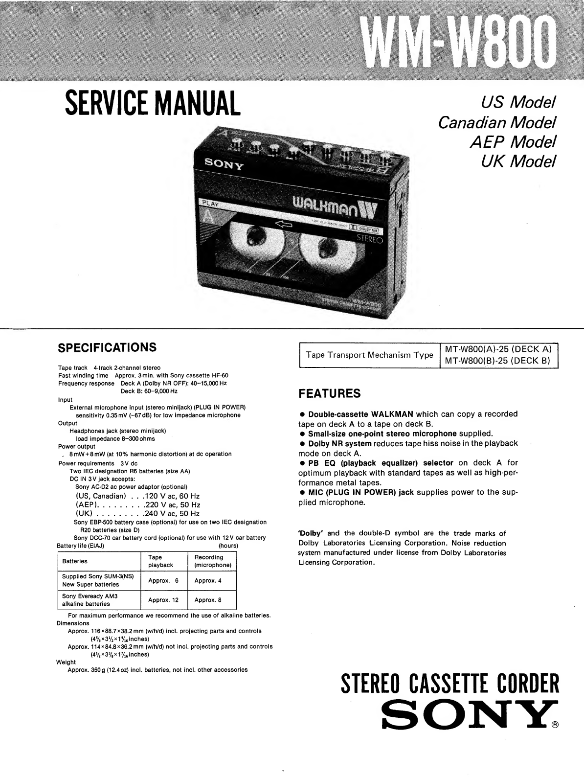
Sony WM-W800 User manual

SERVICE
MANUAL
US
Model
Canadian
Model
AEP
Model
UK
ModeI
SPECIFICATIONS
Tape
track
4-track
2-channel
stereo
Fast
winding
time
Approx.
3min.
with
Sony
cassette
HF-60
Frequency
response
Deck
A
{Dolby
NR
OFF):
40-15,000
Hz
Deck
B:
60-9,000
Hz
Input
External
microphone
input
(stereo
minijack)
(PLUG
IN
POWER)
sensitivity
0.35
mV
(-67
dB)
for
low
impedance
microphone
Output
Headphones
jack
(stereo
minijack)
load
impedance
8-300
ohms
Power
output
.
8
mW
+
8
mW
(at
10%
harmonic
distortion)
at
dc
operation
Power
requirements
3
V
dc
Two
IEC
designation
R6
batteries
(size
AA)
DC
IN
3
V
jack
accepts:
Sony
AC-D2
ac
power
adaptor
(optional)
(US,
Canadian)
.
.
.120
Vac,
60
Hz
(AEP)..
.
.220
Vac,
50
Hz
(UK)..
.240
Vac,
50
Hz
Sony
EBP-500
battery
case
(optional)
for
use
on
two
IEC
designation
R20
batteries
(size
D)
Sony
DCC-70
car
battery
cord
(optional)
for
use
with
12
V
car
battery
Battery
life
(EIAJ)
(hours)
Batteries
Tape
playback
Recording
(microphone)
Supplied
Sony
SUM-3(NS)
New
Super
batteries
Approx.
6
Approx.
4
Sony
Eveready
AM3
alkaline
batteries
Approx.
12
Approx.
8
For
maximum
performance
we
recommend
the
use
of
alkaline
batteries.
Dimensions
Approx.
116x88.7x38.2mm
(w/h/d)
incl.
projecting
parts
and
controls
(4%
x
3
V
2
x
1
9
/
16
inches)
Approx.
114x84.8x36.2mm
(w/h/d)
not
incl.
projecting
parts
and
controls
(4V
2
x
3%
x
1
7
/
16
inches)
Weight
Approx.
350
g
(12.4oz)
incl.
batteries,
not
incl.
other
accessories
Tape
Transport
Mechanism
Type
MT-W800(A)-25
(DECK
A)
MT-W800(B)-25
(DECK
B)
FEATURES
•
Double-cassette
WALKMAN
which
can
copy
a
recorded
tape
on
deck
A
to
a
tape
on
deck
B.
•
Small-size
one-point
stereo
microphone
supplied.
•
Dolby
NR
system
reduces
tape
hiss
noise
in
the
playback
mode
on
deck
A.
•
PB
EQ
(playback
equalizer)
selector
on
deck
A
for
optimum
playback
with
standard
tapes
as
well
as
high-per¬
formance
metal
tapes.
•
MIC
(PLUG
IN
POWER)
jack
supplies
power
to
the
sup¬
plied
microphone.
'Dolby'
and
the
double-D
symbol
are
the
trade
marks
of
Dolby
Laboratories
Licensing
Corporation.
Noise
reduction
system
manufactured
under
license
from
Dolby
Laboratories
Licensing
Corporation.
STEREO
CASSETTE
CORDER

WM-W800
SERVICING
NOTES
Replacing
chip
components
All
chip
components
should
be
connected
and
disconnect¬
ed,
using
a
tapered
soldering
iron
[temperature
of
the
iron
tip:
less
than
280°C
(536°F)],
a
pair
of
tweezers
and
braid¬
ed
wire.
Precautions
for
replacement
1.
Do
not
disconnect
the
chip
component
forcefully.
Otherwise,
the
pattern
may
peel
off.
2.
Never
re-use
a
disconnected
chip
component.
Dispose
of
all
old
chip
components.
3.
To
protect
the
chip
component,
heating
time
for
attach¬
ing
the
component
should
be
within
3
seconds.
o
Removing
chip
components
(1)
R
emoving
solder
at
electrode
Remove
the
solder
at
the
electrode,
using
a
thin
braided
wire.
Do
not
remove
the
solder
of
the
part
(chip
component)
attached
adjacent
to
the
electrode.
(2)
D
i
sconnecting
chip
components
Turn
the
tweezers
with
the
soldering
iron
alternately
applied
to
both
electrodes,
and
the
chip
component
will
be
disconnected.
Take
careful
precautions
while
disconnecting,
because
if
the
chip
component
is
force¬
fully
removed
the
land
may
peel
off.
Never
re-use
a
disconnected
chip
component.
(3)
S
moothing
the
soldered
surface
After
disconnecting
the
chip
component,
remove
the
solder
by
using
a
braided
wire
to
smooth
the
land
surface.
o
Connecting
chip
components
The
value
of
chip
components
is
not
displayed
on
the
main
body.
Take
due
precautions
to
avoid
mixing
new
chip
components
with
other
ones.
(1)
A
pplying
solder
to
land
on
one
side
Apply
a
thin
layer
of
solder
to
the
land
on
one
side
where
the
chip
component
is
to
be
connected.
Too
much
solder
may
cause
bridging.
Small
quantity
of
solder
(2)
S
peedy
soldering
Hold
the
chip
component
at
the
desired
position,
using
tweezers,
and
apply
the
soldering
iron
in
the
arrow-marked
direction.
To
protect
the
chip
compo¬
nent,
heating
time
should
be
within
3
seconds.
(3)
S
p
eedy
soldering
of
electrode
on
the
other
side
Solder
the
electrode
on
the
other
side
in
the
same
way
as
in
(2)
above.
—
2
—

WM-W800
PARTS
IDENTIFICATION
Deck
A
O
Cassette
compartment
(deck
A)
O
0
Headphone
jack
(stereo
minijack)
©MIC
(microphone)
(PLUG
IN
POWER)
jack
(stereo
mini-
jack)
©
PB
EQ
(playback
equalizer)
selector
©
ISS
(Inteference
Suppress
Switch)/DOLBY
NR
selector
©
PUSH
OPEN
button
©
Battery
compartment
operation
buttons
on
deck
A
©
PLAY
(playback)
button
©
STOP
button
©
«
(
fast-forward)
button
0
►
►
(rewind)
button
©
Cassette
compartment
(deck
B)
©
DC
IN
3
V
(external
power
input)
jack
©
VOL
(volume)
control
©
PAUSE
switch
©OPR/BATT
(operation/battery)
indicator
operation
buttons
on
deck
B
©
REC
(record)
button
©
PLAY
(playback)
button
©
STOP
button
©
(fast-forward)
button
©
►►
(rewind)
button
3

WM-W800
SECTION
1
BLOCK
DIAGRAM
4

SECTION
2
DISASSEMBLY
•
Follow
the
disassembly
procedure
in
the
numerical
order
given.
•
Assemble
in
the
reverse
order
of
disassembling.
CONTROL
PANEL
COVER
control
pane
/
cover
CONTROL
PANEL
control
pane!
0
precision
screw
PI.4
x
4
/
0
precision
screw
Ml.4
x
4
O
step
screw
fS\/Q
M1.4\
J
PIT
^
1
-
;<jp
step
screw
A
M1.4
CASSETTE
LID
(B)
cassette
lid
(B)
precision
screw
CASSETTE
LID
(A)
cassette
lid
@
precision
screw
+P1.4
x
1.6
WM-W800
WM-W800
+P1.4
x
3.5
T
lever
bracket
SIDE
PANEL
J
side
panel
DECK
B
0
precision
screw
Ml.4
0
precision
AUDIO
BOARD/DECK
A
0
chassis
fitting
shaft
(B)
0
chassis
fitting
shaft
(B)
audio
board
*4
^
:o)j/
■
vs*

WM-W800
WM-W800
HEAD
CHASSIS
(Deck
A)
REC
LEVER
(Deck
B
only)
REC
lever
0
tension
spring
/
0
x©
precision
screw+P1.4
x
2.0
fV^©
REC
lever
spacer
CONTROL
PLATE
lever
stopper
(C)
spring
j
precision
screw
/\.
I
+P1.4
x
2.0
/
V
//
\
©
Loosen
the
screw.
SLEEVE
T
REEL
precision
screw
+P1.4
x
1.8
07.2
washer
precision
screw
+P1.7x
2.0
control
plate
Installation
(1)
BUTTON
GUIDE
button
collar
V'
button
guide
servo
board
S901/S902
installation
(2)
HEAD
CHASSIS
(Deck
B)
take-up
reel
<t>2.5
washer
^
Spread
the
contact
I
point
of
reel
switch
with
a
pair
of
tweezers.
PI.4
x
1.4\
head
&
?
chassis
ERASE
head
11
<55!
?E^
=
”
1
joint
(A)
0
stopper
washer
1
/
reel
switch
(|
lock
screw
/
h
e
ad
chasste^
©
spring
(Installation)
pinch
lever
07.2
washer
■
head
chassis
-
pinch
lever
'
shaft
(Head
Wiring)
sprins
*&>
h
ead
—
grounding
1
plate
adjustment
©
pinch
lever
©
pinch
lever
.u
azimuth
adjustment
screw
©
precision
screw
\
T
+P1.4
x
1.4
shut-off
spring
stopper
washer
+
precision
screwdriver
head
chassis
head
chassis
/
^
c/s/o
„
sprmg
*
head
chassis
-151
pinch
lever
shaft

SECTION
3
ADJUSTMENTS
WM-W800
PRECAUTION
1.
Clean
the
following
parts
with
a
denatured-
alcohol-moistened
swab:
REC/PB
head
pinch
roller
capstan
rubber
belts
erase
head
2.
Demagnetize
the
REC/PB
head
with
a
head
demagnetizes
(Take
care
not
to
demagnetize
the
erase
head.)
3.
Do
not
use
a
magnetized
screwdriver
for
the
adjustments.
4.
The
adjustments
should
be
performed
with
the
rated
power
supply
voltage
(2.5V)
unless
other¬
wise
noted.
3-1.
MECHANICAL
ADJUSTMENTS
Pinch
Roller
Pressure
Measurement
Procedure:
—
playback
mode
—
1.
Pull
the
spring
scale
in
the
direction
of
the
arrow.
2.
Slowly
return
the
pinch
roller
and
read
the
spring
scale
just
when
the
pinch
roller
starts
to
rotate.
Specifications:
150
±
20g
Torque
Measurement
Perform
with
2.5V
DC
power.
Torque
meter
Meter
reading
FWD
CQ-102C
20
-40
g-cm
(0.28
-
0.56
oz-inch)
FF,
REW
CQ-201B
More
than
60
g-cm
(More
than
0.83
oz-inch)
Back
Tension
CQ-102C
0
-
2.5
g-cm
(0
—
0.034
oz-inch)
Tape
Pulling
Force
CQ-403
More
than
45
g-cm
(More
than
0.62
oz-inch)
Thrust
Clearance
Adjustment
Thrust
clearance
Adjustment
Parts
(Refer
to
exploded
views
and
parts
list.)
Motor
wheel
0.2mm
No.
114
Take-up
reel
0.05-0.15mm
No.
108/110/111
Supply
reel
0.05-0.15mm
No.
117
Reverse
wheel
0.05-0.15mm
No.
152/154
reverse
wheel
-
9
-

WM-W800
3-2.
ELECTRICAL
ADJUSTMENTS
Record/Playback
Head
Azimuth
Adjustment
Procedure:
1.
Mode:
playback
test
tape
P-4-A063
(6.3kHz,
-
1
0
dB)
VTVM
czT
LXj-Ll_J
^
HEAD
PHONES
2.
Turn
the
adjustment
screw
for
the
maximum
output
levels.
If
these
levels
do
not
match,
turn
the
adjustment
screw
until
both
of
output
levels
match
together
within
0.5dB.
.x
within
'output
05dB
level
j
screw
position
Phase
Check
Mode:
playback
test
tape
P-4-AQ63
(6.3kHz,
-10dB)
Note)
After
the
adjustments,
do
not
apply
locking
compound.
oscilloscope
Y"
|
R-CH
^
HEADPHONES
hl8n
□
j/h
—O
pO
L
t-i
J
wt
m
Screen
pattern
Of\
Tape
Speed
Adjustment
Setting:
VOLUME
control:
mechanical
mid
Procedure:
Mode:
playback
test
tape
WS-48A
(3kHz,
OdB)
speed
checker
LFM-30
or
digital
frequency
counter
0
—,_)
i
r
-
-O
0
|
HEADPHONES
Specification:
Deck
A
3,000
-
3,020Hz
(3,010
±0.3%)
Deck
B
2,980
-
3,000Hz
(2,990
±0.3%)
Adjustment
Location:
fast
Deck
A
w
tape
speed
\
adjustment
J
RV601
*
slow
Deck
B
tape
speed
adjustment
RV701
in
phase
45
0
gp°
735
°
180°
good
wrong
10
-

WM-W800
Dolby
NR
Level
Adjustment
Setting:
TAPE
switch:
NORM
DOLBY
NR
switch:
off
VOLUME
control:
minimum
test
tape
P-4-L300
(315
Hz,
OdB)
n
Procedure:
Adjust
RV101
(L-CH),
RV201
(R-CH)
to
obtain
—27.7dB
±0.5dB
(0.030V
to
0.033V)
output
level.
Adjustment
Location:
Audio
board

WM-W800
RECORD
BIAS
ADJUSTMENT
Setting:
VOLUME
control:
MECHANICAL
MID
Procedure:
1.
R
e
c
o
rding
Mode
(Deck
B)
onoOoo'T
blank
tape
CS-10
600n
/
^
■
MIC
'
250Hz
]
315Hz
|
0.0775m
V
(~80dB)
6.3kHz
2.
P
layback
Mode
(Deck
B)
recorded
portion
i
it
3.
S
p
e
c
ifications
250Hz
315Hz
6.3kHz
If
necessary,
change
resistor
connection
and
repeat
the
above
step
1
through
3.
o
mark:
pattern
bridge
LOW
R316
R317
o
o
o
o
Adjustment
Location:
Audio
board
R317
%
1316
Bridge
with
solder.
—12

WM-W800
WM-W800
4-1.
SECTION
4
DIAGRAMS
1
_
1_
l
_I_g_1_*_I_§_|_g_|_7_|_g__|_9
MOUNTING
DIAGRAM
-AUDIO
SECTION
-
■
<
i
>
Note:
•
Color
code
of
sleeving
over
the
end
of
the
jacket.
•
•-:
parts
extracted
from
the
conductor
side.
•
[.!*
■
:
indicates
side
identified
with
part
number.
•
®
:
Through
hole.
@
:
signal
path
®
:
L-CH
signal
path
•
;
R=CH
signal
path
®
'
:
8
+
pattern
R335
TO
SERVO(A)BOARD
(DECK-A)
TO
SERVO(B)BOARD
(DECK-B)

4-2.
SCHEMATIC
DIAGRAM
-AUDIO
SECTION
-
WM-W800
WM-W800
8
I
9
[MAIN
BOARD]
IC30I
BA3304F
PREAMP
IC302
CX20085
DOLBY
NR
CIRCUIT
Q302
2SB8I5
SWITCHING
DECK-A
PLAY
fylODE:
ON
,
FF/REW
MODE:
OFF
WM-W800
Q305
2SB8I5
RIPPLE
FILTER
•
Semiconductor
Lead
Layouts
D302
SLPI35B
BA3304F
CX20085
TA7688F
Note:
•
All
capacitors
are
in
jitF
unless
otherwise
noted.
pF:
jujuF
50
WV
or
less
are
not
indicated
except
for
electrolytics
and
tantalums.
•
All
resistors
are
in
and
l
/
4
\
N
or
less
unless
otherwise
specified.
•
l|>
:
signal
path.
•
signal
path.
•
Components
for
right
channel
have
same
values
as
for
left
channel.
Reference
numbers
are
coded
from
200.
©
BE
SSH
SKSliB
;
g
+
&US.
•
I
1
:
adjustment
for
repair.
©
Voltages
are
dc
with
respect
to
ground
unless
otherwise
noted.
©
Readings
are
taken
under
no-signai
conditions
with
a
VOM
f50kn/Vh
(
)
:
REC
®
Voltage
variations
may
be
noted
due
to
normal
produc¬
tion
tolerances.
®
Power
voltages
.is
DC
3V
and
fed
with
regulated
dc
power
supply
from
DC
JACK.
Voltages
are
dc
with
respect
to
ground
in
PB
mode.
Voltage
variations
may
be
noted
due
to
normal
pro¬
duction
tolerances.
Ref.
No.
Switch
Position
S301
PB
EQ
NORM
S302
DOLBY
NR
OFF
S303
REC/PB
PB
S901-1
POWER
(DECK-A)
OFF
S901-2
FF/REW
(DECK-A)
OFF
S902-1
POWER
(DECK-B)
OFF
S902-2
FF/REW
(DECK-B)
PB
HEAD
HP90I-I
PP227-3602H
,
PB
HEAD
HP90I-2
‘
PP227-3602H
,
REC/PB
HEAD.
HRP90M
r
PP2I7-62026
v
REC/PB
HEAD
HRP90I-2
'
PP217-6202G
.
ON
/OFF
CONTROL
CIRCUIT
4)—I
BIAS
I
I.I5
>
L_J
CONTROL
1
—®—a
L-
L
_._r1
CIRCUIT
DOLBY
NR
LEVELOr-CH)]
RIOli
-J-CI0I
47k
f
*T820p
0.001
T
T33/4V
C
1
0
6
—L
f
12
k
tLCI
0
8
+Lci09
o
'
o,
I
t
i?Lp
DECK-A
PLAY
MODE:
ON
REW
MODE:OFF
ON
Nig
f
Q303I
OFF
V
DECK-A
:R306
FF/REW
'47k
MODE*-ON
0304
r
lDECK-ir]
S90I-2
,
FF/REW
I
■
(
F
F/REW
\.
|
\
MODE
ON
I*
METAL
—
NORM
/Cr02
C204
R206
DOLBY
NR
LEVEL!R-CH)
R20I5
=£C20I
R2
04_
c
2
02
R
2
03
:
1
S
301
-
2
R205
RI2I
(2.3)
10k
|
TO
SERVO
I
(A)BOARD
Q303
2SCI623
SWITCHING
Q304
DTCI43TK
SWITCHING
S303-2
3
REC/PB
|
REC
—
PB
|
I
f
R2II
+L
+1
C206=Pii.
^C208
irC209
T
^FC207|
!
1C304
CX20023
REC/PB
PREAMP
7
4V
IC30411/2)
LCI16
—L
Cl
18
r0.0033-r
0.0047
PB
PREAMP
REF
AMP
1.8
5
|
I
RIPPLE
TT
FILTER
1LC3I3
C3I4+L
"T
10
22
T
3.15V
4V
0
C
i
24
1.3
I/16V
C120
^
R122
33/4V
560
1
REC
PREAMP
C
-C333
tL
C
3
1
2
-n
nm
'T'
J
0
’
001
I
3
ERASE
HEAD
.
HE90I
*
EBF269-36
>
L/C3I9
jli^r
rf0.0022l^iFi
KACI4V#
I-1
S303-4
REC/PB
REC
—
PB
X
+[
3
-
i
s
v
START
OF
RECORDING:
MOMENTARILY
0!!
I
0313
iSrH
no/i
R3I7
22
L
C
4
37
25
riiT^Ti
4V
Q312
2SD596
0313
DTCII4YK
BIAS
OSC
BIAS
SWITCH
0310
GOES
ON
IN
PLAY
MODE
.AND
IC304
IS
PLAYBACK
SIDE.
R3I2
+LC3I6
15k
22
4V
Q309
2SCI623
Q3I0
DTCII4YK
DISCHARGE
SWITCHING
*
RIPPLE
FILTER
5
k
L/16V
Q306
2SB8I5
SWITCHING
I
FOR
PREAMP
OF
DECK-B
(
0306
GOES
OFF
IN
PLAYBACK
)
0306
MODE
OF
DECK-A
'
■
e
K
Q307
2SCI623
SWITCHING
DECK-B
PLAY
MODE:ON
FF/REW
MODE:OFF
DECK-A
PLAY
MODE:OFF
IC303U/2)
Hpower
switch
I-
1C303
TA7688F
HEADPHONE
AMP
l
D302
1REC/BATT|
0316,317
2SAII62
SWITCHING
FOR
MUTING
OF
POWER
ON/OFF
0317
TURNS
ON
WHEN
POWER
ON
>
0316
TURNS
ON
MOMENTARILY
WHEN
POWER
OFF
Q324
2SB8I5
SWITCHING
FOR
POWER
SUPPLY
OF
HEADPHONE
AMP
Q324
R322
f
22k
5
DECK-8
FF/REW/PLAY
MODE:ON
Q326
f
DECK-A
R332
FF/REW/PLAY
MODE
:
ON
4
'
3
k
0325
Q308
2SCI623
f
SWITCHING
™
DECK-B
FF/REW
MODE:
ON
DECK-A
PLAY
MODE:,ON
(2.3)
Q308
GOES
OFF
WHEN
DECK-B
IS
IN
REC
MODE.
TO
SERVO
W
(B)
BOARD
4R329
f
Ik
Q322
0325,326
DTCI43TK
SWITCHING
Q320
DTAI14YK
SWITCHING
HEADPHONE
AMP
MUTING
STARTING
OF
RECORDING
.
.•MOMENTARILY
ON
Q327
DTC1I4YK
SWITCHING
DECK-B
REC
MODE
:
ON
DECK-B
FF/REW/PLAY
MODE
PAUSE
ON/OFF
MODE
s^POWER
ON
jbr
:Q322
MQMENTARll
1
D305
'
D305
IS2837
SjH
MOMENTARILY
ON
Q322
SW
lTCmNG
’^
Q
3
I
9
(
M)
Wa
£H26
__J
0323
2SCI623
T
+
J
DISCHARGE
1
---It*-
0321,328
DTCII4YK
33
SWITCHING
4V
0318,319
2SAII62
SWITCHING
WHEN
POWER
IS
SUPPLIED
TO
DECK-B
WITH
PAUSE
SW
OFF,
CURRENT
FLOWS
FROM
0319
EMITTERBASE
—
C329
—
PAUSE
SW
-*•
GROUND,
TURNING
ON
0319
AND
0321.
0319
AND
Q32I
GO
OFF
WHEN
C329
i$
CHARGED.
WHEN
PAUSE
SW
TURNS
ON
0329
BEGINS
DISCHARGING
THROUGH
TOW
LOOPS:
C329
PLUS
SIDE
—
0318
EMITTER-®-
BASE-®-
R32S-^-
0329
MINUS
SIDE
AND
C329
PLUS
SIDE—
R328
—
R326
—
C329
MINUS
SIDE,
AND
0318
AND
0321
TURN
ON.
WHEN
Q32I
TURNS
ON,
0320
IS
TURNED
ON
AND
THE
HEADPHONE
AMP
OUTPUT
SIGNAL
IS
MUTED.
J30I
HEADPHONE
TO
SERVO-(A)BOARD
—®
TO
SERVO
(B)
BOARD
—©
TO
SERVO
(A)BOARD
-TO
SERVO
(B)
BOARD
S90I-I
POWER
(DECK-A)
/FF/REW/PLAY\
\
MODE
ON
)
S902-I
POWER
(DECK-B)
/
FF/REW/
PLAY
\
l
MODE
ON
i
DRY
BATTERY
(1EC
DESIGNATION
R6)
SIZE
"AA"
2PCS,3V
)
TO
SERVO
(B)
BOARD
CX20023
KiiLiliUil
■
Tllllllllll
SLP135B
2SA1162
2SB624-BU4
2SB815
2SC1623
2SD596
DTC114YK
DTC143TK

WM-W800
WM-W800
WM-W800
B
H
8
10
11
12
13
14
15
16
17
18
19
20
21
22
4-3.
MOUNTING
DIAGRAM
-SERVO
SECTION
-
Note:
•
•-
:
Parts
extracted
from
the
conductor
side.
•
<8>
:
Through
hole.
si:
B
+
pattern
-
2
0
-
DECK-A
(PB
TO
MAIN
BOARD
SIDE
A
Q
—<
I
~
5
>
603
602
601
—
Q
703
604
702
701
0
1C
609
608
IC60I
607
704
606
709
708
IC70I
707
706
1C
(SIDE
B)
Note
on
schematic
diagram:
•
All
capacitors
are
in
nf
unless
otherwise
noted.
pF:
wiF
50
WV
or
less
are
not
indicated
except
for
electrolytics
and
tantalums.
•
All
resistors
are
in
fit
and
V
4
W
or
less
unless
otherwise
specified.
BEEssa®
;
fj+
bus.
r
I
:
adjustment
for
repair.
®
Voltages
are
dc
with
respect
to-ground
unless
otherwise
noted.
®
•
Readings
are
taken
under
no-signal
conditions
with
a
VQM
(5Qk£2/Vh
®
Voltage
variations
may
be
noted
due
to
normal
produc¬
tion
tolerances.
•
Power
voltage
Is
DC
3V
and
fed
with
regulated
dc
power
supply
from
DC
JACK.
Voltages
are
dc
with
respect
to
ground
in
PB
mode.
Voltage
variations
may
be
noted
due
to
normal
pro¬
duction
tolerances,
•
Switch
Ref.
No.
Switch
Position
S601
5903
5904
PAUSE
REEL
(DECK-A)
REEL
(DECK-B)
OFF
1
PAUSE
|
OFF--ON
21
—22
B
H

WM-W800
WM-W800
i
8
10
11
12
13
14
15
B
H
4-4.
SCHEMATIC
DIAGRAM
(Refer
to
page
22
for
notes.)
-
SERVO
SECTION
-
0603
2SB624,0604
2SCI623-L6
-MOTOR
DRIVE
fMOTOR
COILl
f
SERVO
(A)
1(A)
BOARD
1
L
BOARD
1
8
mSec
JTH.
^(T0
MAIN
BOARD)
0
MAIN
BOARD)
DECK-A
B
+
IS
APPLIED
IN
FF/REW/PLAY
MODE
©
(
T
OMAIN
BOARD)
DECK-A
B+IS
APPLIED
IN
FF/REW
MODE
(TO
MAIN
BOARD)
B
+
(TO
MAIN
BOARD)
(TO
MAIN
BOARD)
-(n
DECK-B
^
B+
IS
APPLIED
IN
FF/REW/PLAY
MODE
(TO
MAIN
BOARD)
-A
DECK-B
^
B+IS
APPLIED
IN
FF/REW
MODE
-23

REVISED
wM-wsoo
SECTION
5
I--'
-
EXPLODED
VIEWS
AND
PARTS
LIST
NOTE:
•
The
mechanical
parts
with
no
reference
*
Items
marked
"
*
"
are
not
stocked
since
•
The
construction
parts
of
an
assembled
number
in
the
exploded
views
are
not
they
are
seldom
required
for
routine
part
are
indicated
with
a
collation
supplied.
service.
Some
delay
should
be
antici-
number
in
the
remark
column.
pated
when
ordering
these
items.
(D
1
X-3325-115-1
(BLACK)...,
.LID
(A)
ASSY,
CASSETTE
10
3-325-109-01
SPRING
X-3325-116-1
SILVER)..,
.LID
(A)
ASSY,
CASSETTE
11
3-325-125-01
TERMINAL
(A),
BATTERY
3
X-3325-101-1
BRACKET
ASSY,
T
LEVER
—12
3-325-107-01
TERM
1NAL(B),
BATTERY
4
7-627-850-47
(SILVER)..,
.SCREW,
PRECISION
+P
1.4X1.6*51
—13
3-325-102-01
TERM
1NAL
(C),
BATTERY
7-627-850-48
(BLACK)...,
.SCREW,
PRECISION
+P
1.4X1.®^
14
3-325-117-01
SCREW
(Ml.4),
STEP,
SPECIAL
6
7-627-850-17
(SILVER)..,
.SCREW,
PRECISION
+P
1.4X2.5
15
7-627-850-68
SCREW,
PRECISION
+P
1.4X4
7-627-850-18
(BLACK)...,
.SCREW,
PRECISION
+P
1.4X2.5
16
3-325-128-11
COVER,
CONTROL
PANEL
7
X-3325-105-1
LID
(B)
ASSY
(BLACK),
CASSETTE
17
3-527-213-00
LABEL,
SERIAL
NUMBER
8
A-3043-104-A
PANEL
ASSY,
,
CONTROL
18
9-911-815-01
CUSHION
9
3-325-124-01
CLAW,
LOCK,
,
COVER
19
*3-703-710-01
STICKER,
SONY
SYMBOL
(12)
21
*3-323-130-11
CUSHION,
CASSETTE
25
-

WM-W800

No.
Part
No.
Description
Remarks
101
3-315-301-11
TERMINAL
BOARD,
MOTOR
102
3-831-441-XX
CUSHION
103
X—3325—111—1
STOPPER
ASSY,
T
104
7-627-850-37
SCREW,
PRECISION
+P
1.4X1.4
105
3-315-412-00
CONTACT,
OUTSERT
106
7-627-850-37
SCREW,
PRECISION
+P
1.4X1.4
107
X—3315—314—0
CHASSIS
ASSY,
TAKE-UP
REEL
109
X-3315-315-0
GEAR
ASSY,
TAKE-UP
REEL
110
3-317-701-01
WASHER
3-317-701-11
WASHER
111
3-315-384-01
WASHER,
STOPPER
(t=0.13)
3-315-384-11
WASHER,
STOPPER
(t=0.25)
112
A-3133-205-A
WHEEL
ASSY
BLOCK
ASSY,
MOTOR
113
A-3133-206-A
RIVETING
ASSY,
MOTOR
SLEEVE
114
3-315-332-01
SPACER
(t=0.05)
3-315-332-11
SPACER
(t=0.1)
3-315-332-21
SPACER
(t=0.125)
115
3-315-390-00
PLATE,
HYSTERESIS
116
3-324-546-01
GEAR
(OUTSERT),
REEL,
SUPPLY
117
3-315-384-01
WASHER,
STOPPER
(t=0.13)
3-315-384-11
WASHER,
STOPPER
(t=0.25)
3-315-384-21
WASHER,
STOPPER
(t=0.2)
3-315-384-31
WASHER,
STOPPER
(t=0.3)
118
*3-315-419-00
PLATE,
SHIELD
119
3-315-485-01
SCRWE
(Ml.4X2.3),
PRECISION
120
3-317-706-01
SCREW
(Ml.4X2.3)
121
X—3325—113—
LEVER
ASSY,
REC
122
3-325-150-01
BUTTON,
REC
123
3-305-528-11
SCREW,
STOPPER
124
3-320-349-01
CLAW,
REC
LOCK
125
X-3320-309-1
ARM
ASSY,
JOINT,
E
HEAD
126
3-320-350-11
SPRING
127
3-578-224-11
WASHER
No.
Part
No.
Description
Remarks
128
X—3315—343—1
SLEEVE
COMP
ASSY
129
7-627-850-07
SCREW,
PRECISION
+P
1.4X2
130
7-627-552-28
SCREW,
PRECISION
+P
1.7X2
131
*3-325-155-01
CLAMP
132
3-315-399-00
COLLAR,
BUTTON
133
*3-317-578-01
STOPPER,
LEVER
(C)
134
3-325-171-01
SCREW
135
3-308-557-00
(DECK
A)....LUG,
PLATE,
DIA.
1.7
3-325-147-01
(DECK
B)_RETAINER,
LEAD
136
3-320-420-01
STOPPER,
FR
LEVER
(C)
137
3-325-149-01
SPACER,
LEVER,
REC
138
3-325-145-01
SPRING,
TENSION
139
7-627-850-78
PRECISION
SCREW
+P
1.4X1.8
140
X-3317-508-1
FLYWHEEL
ASSY
141
3-315-495-01
WASHER
(t=0.25)
3-315-495-11
WASHER
(t=0.13)
3-315-495-21
WASHER
(t=0.2)
3-315-495-31
WASHER
(t=0.3)
142
3-315-417-00
BUSHING,
CAPSTAN
143
3-315-405-00
BELT
144
3-324-524-01
SLIDER,
JOINT
145
3-325-116-01
PLATE,
ORNAMENTAL,
CHASSIS
146
A-3102-071-A
CHASSIS
(A)
BLOCK
ASSY,
REEL
147
A-3102-072-A
CHASSIS
(B)
BLOCK
ASSY,
REEL
148
3-324-520-01
SPRING,
TENSION
149
3-703-929-01
CUSHION
(G)
150
3-317-702-01
SPACER
(D)(t=0.13)
3-317-702-11
SPACER
(D)(t=0.2)
3-317-702-21
SPACER
(D)(t=0.25)
901
1-462-225-11
COIL,
MOTOR
(STATOR)
902
A-3065-051-A
MOUNTED
PCB
(A),
SERVO
903
A-3065-052-A
MOUNTED
PCB
(B),
SERVO
—27

WM-W800
No^
Part
No.
Description
Remarks
151
X-3315-308-0
WHEEL
ASSY,
REVERSE
152
3-315-415-00
WASHER
1.5
DIA.(t=0.075)
3-315-415-11
WASHER
2.3
DIA.(t=0.1)
3-315-416-00
WASHER
1.2
DIA.(t=0.1)
3-315-416-21
WASHER
2.5
DIA.{t=0.188)
153
X-3315-307-0
LEVER
(B)
ASSY,
FR
154
3-315-414-00
WASHER
(t=0.25)
3-315-414-11
WASHER
(t=0.188)
3-315-414-21
WASHER
(t=0.13)
155
X-3315-360-1
PLATE
ASSY,
CONTROL
156
3-325-139-01
BUTTON,
PLAY
157
3-325-142-01
BUTTON,
STOP
158
3-305-528-21
SCREW,
STOPPER
159
3-305-528-11
SCREW,
STOPPER
No.
Part
No.
Description
Remarks
160
X-3324-505-1
PLATE
ASSY,
CONTROL
161
X—3325—117—1
LEVER
ASSY,
PLAY
162
‘X-3315-304-5
PLATE
ASSY,
LOCK
163
3-315-384-41
WASHER,
STOPPER
164
3-315-331-00
SPRING,
COMPRESSION
165
3-325-140-01
BUTTON,
FF/REW
166
3-315-395-00
SCREW,
BUTTON
167
7-627-551-47
SCREW,
PRECISION
+P
1.4X1.4
168
3-315-341-00
SPRING,
TENSION
(POWER
TENSION)
169
3-315-343-00
SPRING,
TENSION
(POWER
TENSION)
170
3-315-396-00
LEVER
(C),
F.R
171
3-315-397-00
SPRING,
TENSION
(POWER
TENSION)
172
A-3125-002-A
WHEEL
BLOCK
ASSY,
REVERSE
28

No,
Part
No.
Description
Remarks
201
3-325-126-01
KNOB,
PAUSE
204
3-324-541-01
PLATE,
BASE,
HEAD
205
3-324-531-01
CLAMP
206
7-627-850-37
SCREW,
PRECISION
+P
1.4X1.4
208
3-320-343-01
JOINT
(A),
E
HEAD
209
3-320-344-01
JOINT
(B),
E
HEAD
210
3-320-352-01
SPRING,
COMPRESSION
211
7-627-451-28
SCREW,
PRECISION
+K
1.4X3
212
3-703-816-01
SCREW
(Ml.4X2.0),
SPECIAL
HEAD
213
3-324-543-01
ARM,
HEAD,
E
214
X—3324—507—1
CHASSIS
ASSY,
HEAD
215
3-324-551-01
SHAFT
(B),
ARM,
E
HEAD
No.
Part
No.
Description
Remarks
216
3-324-542-01
SPRING,
COMPRESSION
217
3-324-544-01
WASHER
(DIA.
2.3-1)
218
3-324-540-01
SCREW,
ADJUSTMENT,
AZIMUTH
219
X—3325—110—1
PINCH
LEVER
ASSY
220
3-315-394-00
SPRING
221
3-315-393-00
SHAFT,
PINCH
LEVER
222
3-315-384-11
WASHER,
STOPPER
(t=0.25)
223
3-315-357-00
SPRING
224
3-315-384-31
WASHER,
STOPPER
(t=0.3)
225
3-315-406-00
SPRING
226
7-627-850-37
SCREW,
PRECISION
+P
1.4X1.4
227
3-325-144-01
GUIDE,
BUTTON
—29

WM-W800
(6)
DECK
A
No.
Part
No.
Description
Remarks
No.
Part
No.
Description
251
A-3163-080-A
CHASSIS
BLOCK
ASSY,
T
REEL
259
3-315-394-00
SPRING
252
3-315-430-00
TABLE,
HEAD
260
3-315-393-00
SHAFT,
PINCH
LEVER
253
3-315-463-00
PLATE,
GROUND,
HEAD
261
3-315-384-41
WASHER,
STOPPER
254
3-315-484-02
SCREW
(M2X3),
HEAD,
WASHER
262
3-315-357-00
SPRING
255
3-315-431-00
CHASSIS,
HEAD
263
3-315-406-00
SPRING
256
3-315-391-00
SPRING
264
7-627-850-37
SCREW,
PRECISION
+P
1.4X1.4
257
3-315-392-00
SCREW,
ADJUSTMENT
265
3-325-144-01
GUIDE,
BUTTON
258
X—3325—110—1
PINCH
LEVER
ASSY
—
3
0
—
Remarks
Other manuals for WM-W800
1
Table of contents
Other Sony Cassette Player manuals

Sony
Sony TC-WE305 User manual

Sony
Sony CFD-S700 User manual

Sony
Sony TC-S3 User manual

Sony
Sony WM-GX410 - Walkman User manual

Sony
Sony Walkman WM-FX241 User manual

Sony
Sony Walkman WM-FX251 User manual

Sony
Sony Walkman WM-FX195 User manual

Sony
Sony TC-TX101 User manual

Sony
Sony TC-KB820S User manual

Sony
Sony WM-FS555J - Walkman User manual

Sony
Sony Walkman WM-FX28 User manual

Sony
Sony TC-KE600S User manual

Sony
Sony HVR-M25J User manual

Sony
Sony Walkman WM-GX221 User manual

Sony
Sony FX323 User manual

Sony
Sony Walkman WM-DD 3 User manual

Sony
Sony Walkman WM-FX488 User manual

Sony
Sony HCD-EP30 User manual

Sony
Sony WALKMAN WM-9 User manual

Sony
Sony Walkman wm-FX105 User manual