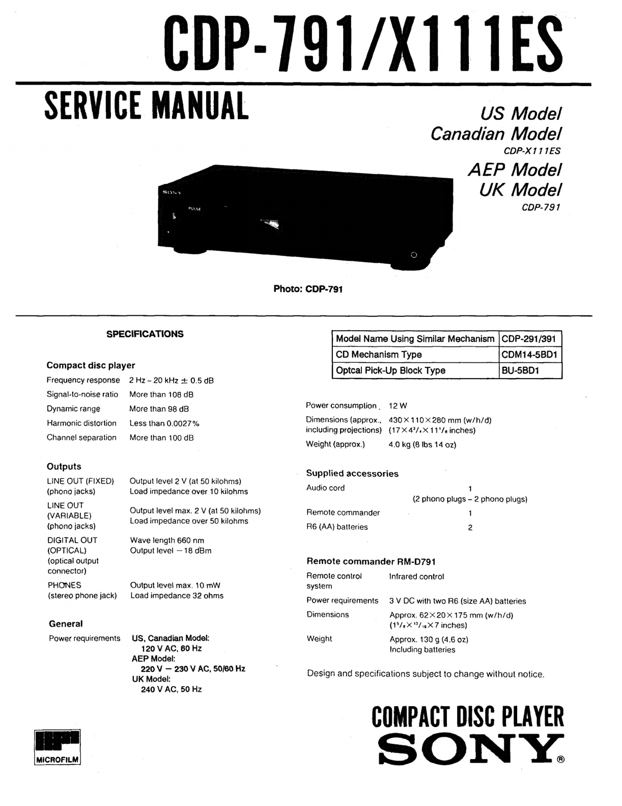
Sony CDP-791 User manual
Other Sony CD Player manuals

Sony
Sony Walkman D-SJ303 User manual

Sony
Sony MZ-R500 User manual

Sony
Sony HCD-GNX660 User manual

Sony
Sony D-MJ95 Primary User manual

Sony
Sony CFD-W57 - Cd Radio Cassette-corder User manual

Sony
Sony CFD-S03CPL User manual

Sony
Sony WX-GT80UI User manual

Sony
Sony CDP-C245 User manual

Sony
Sony DVP-NC615 User manual

Sony
Sony WM-EX570 User manual

Sony
Sony HCD-H50 User manual

Sony
Sony CDX-M800 User manual

Sony
Sony DVP-FX780 User manual

Sony
Sony CD Walkman D-EJ885 User manual

Sony
Sony CDX-2160 User manual

Sony
Sony CDX-C8050X - Fm/am Compact Disc Player User manual

Sony
Sony MZ-N10 User manual

Sony
Sony CDX-GT400 - Fm/am Compact Disc Player User manual

Sony
Sony D-NE336CK - Atrac Cd Walkman Installation instructions

Sony
Sony Discman D-E440 User manual