manuals.online logo
Brands
  1. Home
  2. •
  3. Brands
  4. •
  5. Sony
  6. •
  7. CD Player
  8. •
  9. Sony CDP-C265 User manual

Sony CDP-C265 User manual

Other manuals for CDP-C265

1

This manual suits for next models

1

Other Sony CD Player manuals

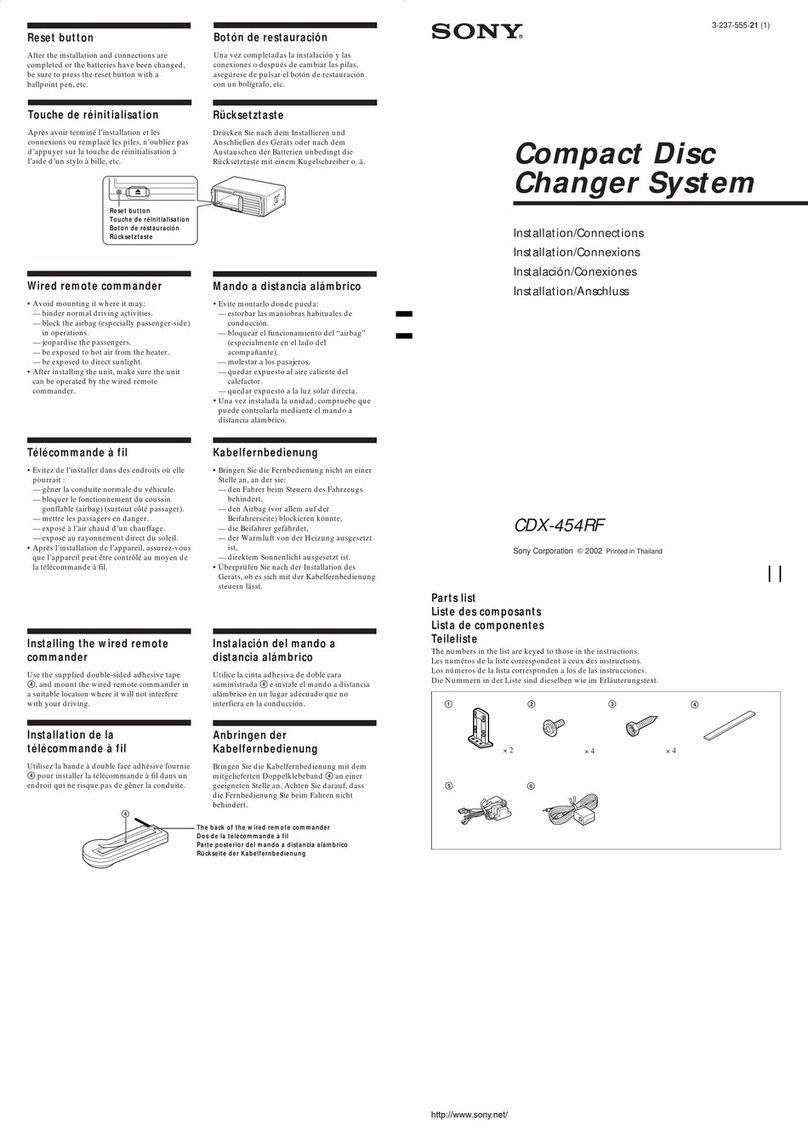
Sony CDX-G1180UM User manual

Sony

Sony CDX-G1180UM User manual

Sony CDX GT52W - MP3 / WMA Instruction Manual

Sony

Sony CDX GT52W - MP3 / WMA Instruction Manual

Sony CDX-605 - Compact Disc Changer User manual

Sony

Sony CDX-605 - Compact Disc Changer User manual

Sony CDX-C410 User manual

Sony

Sony CDX-C410 User manual

Sony CDX-805 User manual

Sony

Sony CDX-805 User manual

Sony MZ-N707 OpenMG Jukebox NOTES on installing &... User manual

Sony

Sony MZ-N707 OpenMG Jukebox NOTES on installing &... User manual

Sony MCE-F500 User manual

Sony

Sony MCE-F500 User manual

Sony AVD-C700ES - 5 Dvd Changer/receiver User guide

Sony

Sony AVD-C700ES - 5 Dvd Changer/receiver User guide

Sony CDP-C661 Operating Instructions (CD... User manual

Sony

Sony CDP-C661 Operating Instructions (CD... User manual

Sony CD Walkman D-193 User manual

Sony

Sony CD Walkman D-193 User manual

Sony CDX-GT610UI - Cd Receiver With Ipod... User manual

Sony

Sony CDX-GT610UI - Cd Receiver With Ipod... User manual

Sony SCD-CE775 Marketing User manual

Sony

Sony SCD-CE775 Marketing User manual

Sony G70L User manual

Sony

Sony G70L User manual

Sony CDX-415RF User manual

Sony

Sony CDX-415RF User manual

Sony CDP-CX200 User manual

Sony

Sony CDP-CX200 User manual

Sony MD Walkman MZ-R91 User manual

Sony

Sony MD Walkman MZ-R91 User manual

Sony CDX-GT40U User manual

Sony

Sony CDX-GT40U User manual

Sony Walkman MZ-R30 User manual

Sony

Sony Walkman MZ-R30 User manual

Sony CDX-1000RF User manual

Sony

Sony CDX-1000RF User manual

Sony CDP-CE500 User manual

Sony

Sony CDP-CE500 User manual

Sony CDP-C235 User manual

Sony

Sony CDP-C235 User manual

Sony CFD-E100WHITE User manual

Sony

Sony CFD-E100WHITE User manual

Sony CDP-XE700 User manual

Sony

Sony CDP-XE700 User manual

Sony CFDF17CP User manual

Sony

Sony CFDF17CP User manual

Popular CD Player manuals by other brands

Arcam CD23 Handbook

Arcam

Arcam CD23 Handbook

Sanyo MCD-Z1F Service manual

Sanyo

Sanyo MCD-Z1F Service manual

JVC RC-ST3SL instructions

JVC

JVC RC-ST3SL instructions

Technics SL-P9066 operating instructions

Technics

Technics SL-P9066 operating instructions

Marantz HD-CD1 quick start guide

Marantz

Marantz HD-CD1 quick start guide

Philips AZ1140 Instrukcja obs?ugi

Philips

Philips AZ1140 Instrukcja obs?ugi

Alpine 7909 owner's manual

Alpine

Alpine 7909 owner's manual

JVC CH-X350 instructions

JVC

JVC CH-X350 instructions

RCA RP-7923 instruction manual

RCA

RCA RP-7923 instruction manual

Pioneer DEH-P3550MP XM Operation manual

Pioneer

Pioneer DEH-P3550MP XM Operation manual

Philips Shockproof AX2102 brochure

Philips

Philips Shockproof AX2102 brochure

Philips CD582 user manual

Philips

Philips CD582 user manual

Philips AZ 6821 operating manual

Philips

Philips AZ 6821 operating manual

Lasonic MSU-2020 user manual

Lasonic

Lasonic MSU-2020 user manual

Denon DCD-1420 Service manual

Denon

Denon DCD-1420 Service manual

Panasonic SJ-MR100 operating instructions

Panasonic

Panasonic SJ-MR100 operating instructions

Onkyo DX-7210 instruction manual

Onkyo

Onkyo DX-7210 instruction manual

Cambridge Audio SONATA CD30 manual 

Cambridge Audio

Cambridge Audio SONATA CD30 manual 

manuals.online logo
manuals.online logoBrands
  • About & Mission
  • Contact us
  • Privacy Policy
  • Terms and Conditions

Copyright 2025 Manuals.Online. All Rights Reserved.

SERVICE
MANUAL
Photo
:
CDP-C265
CDP-C265/C365
US
Model
Canadian
Model
AEP
Model
UK
Model
Australian
Model
CDP-C265/C365
E
Model
CDP-C365
CDP-C235/C335
CDM27A1-5BD13
BU-5BD13
Compact
Disc
Player
System
Laser
Wavelength
Frequency
response
Signal
to
noise
ratio
Dynamic
range
Harmonic
distortion
Channel
separation
Output
LINE
OUT
(phono
jacks)
General
Power
requirements
Power
consumption
Dimensions
(w/h/d)
SPECIFICATIONS
Compact
disc
digital
audio
system
Semiconductor
laser
780-790
nm
2
Hz-20
kHz
(+0.5
dB)
More
than
102
dB
More
than
98
dB
Less
than
0.0045%
More
than
100
dB
Output
level
2
V
(at
50
kilohms)
Load
impedance
over
10
kilohms
Model
for
US
and
Canadian
120V
AC,
60Hz
Model
for
AEP,
German,
UK,
Singapore,
Malaysia
220
—
230V
AC,
50/60Hz
Model
for
Australian
240V
AC,
50/60Hz
Model
for
E
110—120V,
220—240V
AC,
50/60Hz
14W
Approx.
430
x
125
x
385
mm
(17
x
5
x
151/4
inches)
Including
projecting
parts
and
controls
Mass
Remote
Commander
Remote
control
system
‘Power
requirements
Dimensions
Mass
Supplied
accessories
KSS-240A
Approx.
5.6
kg,
net
(12
Ibs
60z)
RM-D335
(CDP-C365
only)
Infrared
control
3
V
DC
with
two
size
AA
batteries
(IEC
designation
R6)
45
x
185
x
20
mm
(w/h/d)
(1
13/16
x
7
3/8
x
13/16
inches)
100
g
(3.5
oz)
including
batteries
Audio
signal
connecting
cord
(phono
plug
x
2
—
phono
plug
x
2)
(1)
Remote
commander
(1)
(CDP-C365
only)
Sony
SUM-3
(NS)
batteries
(2)
(CDP-C365
only)
AC
plug
adaptor
(1)
(CDP-C365
E
model
only)
Design
and
specifications
are
subject
to
change
without
notice.
COMPACT
DISC
PLAYER
SONY.
The
following
caution
label
is
located
inside
of
the
unit.
CAUTION
*
INVISIBLE
LASER
RADIATION
WHEN
OPEN,
AVOID
EXPOSURE
TO
BEAM
A
.
USYNLIG
LASERSTRALING
VEO
ABNING
NAR
DVARSEL
SIKKERHEOSAFBRYOERE
ER
UDE
AF
FUNKTION
UNOGAUOS
ZTTELSE
FOR
STRANING
:
AVATTAESSA
JA
SUOJALUKITUS
OHITETTAESSA
OLET
ALTTIINA
LASERSATEILYLLE
{
LASERSTRALING
NAR
DENNA
DEL
AR
OPPNAD
OCH
SPARREN
AR
URXOPPLAD
ADVARSEL
:
USYALIG
LASERSTRALING
NAR
OEKSEL
APNES
UNNGA
EKSPONERING
FOR
STRALEN
VAROi
VARNING
This
Compact
Disc
player
is
classified
as
a
CLASS
1
LASER
product.
The
CLASS
1
LASER
PRODUCT
MARKING
is
located
on
the
rear
exterior.
CLASS
1
LASER
PRODUCT
LUOKAN
1
LASERLAITE
KLASS
1
LASERAPPARAT
CAUTION
Use
of
controls
or
adjustments
or
performance
of
procedures
other
than
those
specified
herein
may
result
in
hazardous
radiation
exposure.
SAFETY-RELATED
COMPONENT
WARNING
!!
COMPONENTS
IDENTIFIED
BY
MARK
A\
OR
DOTTED
LINE
WITH
MARK
A\
ON
THE
SCHEMATIC
DIAGRAMS
AND
IN
THE
PARTS
LIST
ARE
CRITICAL
TO
SAFE
OPERATION.
REPLACE
THESE
COMPONENTS
WITH
SONY
PARTS
WHOSE
PART
NUMBERS
APPEAR
AS
SHOWN
IN
THIS
MANUAL
OR
IN
SUPPLEMENTS
PUBLISHED
BY
SONY.
TABLE
OF
CONTENTS
Section
Title
Page
SECTION
T:.
“GENERAL
asses
sasisasdearecnveevivigaaneceevareteaeans
5
SECTION
2.
DISASSEMBLY
2-1.
Case,
Bottom
Plate
and
Front
Panel
........0....ccceeeceeeeeee
6
2-2.
Back
Panel
and
Disc
Table
.00000..
eee
eecceeeseeeeeeenenes
6
2-3.
Optical
Pick-up
Block
ASSEMDIy
«0.0.0...
ce
ceeeesceteeeeeteees
7
2-4.
Bracket
(Gear)
ASSEMDLyY
ese
cseseseeseescreeeeeeeees
7
SECTION
3.
ELECTRICAL
BLOCK
CHECKING
........
8
SECTION
4.
DIAGRAMS
AnT.>
BIOCK:
DIAG
CAIN
atsasancesgyccessccccetce
vance
sen
ssateastees
Gbtewste
nantes
10
4-2.
Circuit
Boards
Location
0...
cceesssneeecsessesnsseeneesseeees
12
4-3.
Semiconductor
Lead
Layouts
.......
cc
eeseeecesseeeeseeeeeenee
12
4-4.
Printed
Wiring
Board
o0......
cece
sccestteceecnsseseeesnensseeeeees
13
4-5.
Schematic
Diagram
.....ccccccscesecsesscsssesssseestsssseseensseeseees
17
4-6.
IC
BlOCK.
DidQraims
esi
sevecssedsivccnsivesecaviegninesdacivasvedeonavadtievass
21
4-7.
\C
Pin
Functions
*
1C101
Focus/Tracking
Sled
Servo,
EFM
Comparator
(CXD2515Q)
.00....
eee
seseesesereeseeeseecnes
23
*
1C103
Digital
Filter,
D/A
Converter
(OX
D256
SAM-
TG)
sscccevnipitavetentvnsityponamnasaaviotsnantccsaxions
25
*
1C401
System
Control
(CXP82316-050Q)
........
ee
26
SECTION
5.
EXPLODED
VIEWS
5-1.
Front
Panel
and
Case
Sections
...........ccccesseessesssesenees
27
5-2.
Backpanel
and
Disk
Table
Section
............cccssseeeeeeeeee
28
5-33,
“CHASSIS
SOCtON
siscsessc:
tanicariede
car
cateesrainerantonteatieane
29
5-4,
Base
Unit
Section
(BU-5BD13)
wu.
ees
ceeeeeeereeeeeaee
30
SECTION
6.
.
ELECTRICAL
PARTS
LIST...........0000..
31
ATTENTION
AU
COMPOSANT
AYANT
RAPPORT
A
LA
SECURITE!!
LES
COMPOSANTS
IDENTIFIES
PAR
UNE
MARQUE
A\
SUR
LES
DIAGRAMMES
SCHEMATIQUES
ET
LA
LISTE
DES
PIECES
SONT
CRITIQUES
POUR
LA
SECURITE
DE
FONCTIONNEMENT.
NE
REMPLACER
CES
COMPOSANTS
QUE
PAR
DES
PIECES
SONY
DONT
LES
NUMEROS
SONT
DONNES
DANS
CE
MANUEL
OU
DANS
LES
SUPPLEMENTS
PUBLIES
PAR
SONY.
MODEL
IDENTIFICATION
—
BACK
PANEL
—
4-971(ZZZ
CDP-C265
US
Model
:080-5C]
(U)
(made
in
malaysia)
US
Model
:
532-40]
(U)
(made
in
china)
Canadian
Model
:
532-11
(CA)
AEP
Model
:
080-60]
(CED)
UK
Model
:
080-70)
(CEK)
German
Model
:
532-31
(CEE)
Australian
Model
:
080-80]
(AU)
CDP-C365
US
Model
:
080-0L
(U)
Canadian
Model
:
532-00)
(CA)
AEP,
Singapore,
Malaysia
Model
:080-1(]
(CED)
UK
Model
:
080-20]
(CEK)
German
Model
:
532-201)
(CEE)
E
Model
080-40]
(E2/E3)
Australian
Model
:
080-30)
(AU)
NOTES
ON
HANDLING
THE
OPTICAL
PICK-UP
BLOCK
OR
BASE
UNIT
The
laser
diode
in
the
optical
pick-up
block
may
suffer
electrostatic
breakdown
because
of
the
potential
difference
generated
by
the
charged
electrostatic
load,
etc.
on
clothing
and
the
human
body.
During
repair,
pay
attention
to
electrostatic
breakdown
and
also
use
the
procedure
in
the
printed
matter
which
is
included
in
the
repair
parts.
;
The
flexible
board
is
easily
damaged
and
should
be
handled
with
care.
NOTES
ON
LASER
DIODE
EMISSION
CHECK
The
laser
beam
on
this
model
is
concentrated
so
as
to
be
focused
on
the
disc
reflective
surface
by
the
objective
lens
in
the
optical
pick-up
block.
Therefore,
when
checking
the
laser
diode
emission,
observe
from
more
than
30
cm
away
from
the
objective
lens.
SAFETY
CHECK-OUT
(US
model
only)
After
correcting
the
original
service
problem,
perform
the
following
safety
checks
before
releasing
the
set
to
the
customer:
|
Check
the
antenna
terminals,
metal
trim,
“metallized”
knobs,
screws,
and
all
other
exposed
metal
parts
for
AC
leakage.
Check
leakage
as
described
below.
LEAKAGE
The
AC
leakage
from
any
exposed
metal
part
to
earth
ground
and
from
all
exposed
metal
parts
to
any
exposed
metal
part
having
a
return
to
chassis,
must
not
exceed
0.5
mA
(500
microampers).
Leakage
current
can
be
measured
by
any
one
of
three
methods.
1.
A
commercial
leakage
tester,
such
as
the
Simpson
229
or
RCA
WT-540A.
Follow
the
manufacturers’
instructions
to
use
these
instruments.
2.
<A
battery-operated
AC
milliammeter.
The
Data
Precision
245
digital
multimeter
is
suitable
for
this
job.
3.
Measuring
the
voltage
drop
across
a
resistor
by
means
of
a
VOM
or
battery-operated
AC
voltmeter.
The
“limit”
indication
is
0.75
V,
so
analog
meters
must
have
an
accurate
low-voltage
scale.
The
Simpson
250
and
Sanwa
SH-63Trd
are
examples
of
a
passive
VOM
that
is
suitable.
Nearly
all
battery
operated
digital
multimeters
that
have
a
2V
AC
range
are
suitable.
(See
Fig.
A)
To
Exposed
Metal
Parts
on
Set
AC
aa
voltmeter
(0.75V)
=
Earth
Ground
Fig.
A.
Using
an
AC
voltmeter
to
check
AC
leakage.
HOW
TO
OPEN
THE
DISC
TRAY
WHEN
POWER
SWITCH
TURNS
OFF
Insert
a
tapering
driver
into
the
aperture
of
the
unit
bottom,
and
turn
in
the
direction
of
arrow
(to
OUT
direction).
*
To
close
the
disc
tray,
turn
the
driver
in
the
reverse
direction
(to
IN
direction).
Tray
NOTE
FOR
MAIN
GEAR
INSTALLATION
@
Stopper
washer
(5}
©
Install
the
MAIN
GEAR
as
show
in
the
drawing
@
Set
the
mark
of
@
Slide
the
SET
LEVER
to
the
ROTARY
ENCODER
arrow
©)
direction
—4—
uoyng
Y5qV4
El]
uoyng
(NVOS
‘W)
NVOS
OISNW
EW
uoyng
(do}s)
m
[ii]
uonng
dIMS
OSIC
by]
uoung
YV3T9
[6]
suo}ng
(yoreas
enue)
<</>P>
[8]
SUO]ING
(SV)
He<4/>P4
[7]
uoyng
(ssned)
i
[5]
uoyng
(Ae\d)
<<
[5]
suoyng
G--
OSid
[7]
UOHN
(O}
49A0)
OL<
fF]
SUOHING
OUSWINN
fz]
uonng
WVYDOudd
uoyng
31Sd4NHS
uoHNg
ANNILNOO
suonng
S0OW
AW
1d
[7]
“JOSUSS
SISNYY
OBO
NY
JO}
UOHBIABIgGe
aU;
SI
SW
*
uoling
FONVHO-XG
fe
UOHNG
YOSHO
Eq
uonng
Yv310
Ea
uoyng
F0VS
AWIL/LIGS
fz]
UO}ING
(Q}.
48A0)
OL<
fq
SUO}VNG
OVSWINN
64]
uoying
Y3AGVS
fi
uowng
SWIL
Zi
uoyng
1W3ad3y
By
uonng
HOYV3S
MV3d
&i]
uoywng
3SO10/NadO
¥
[Fi]
uonng
dIMS
OSIG
Ei]
uoyng
(do}s)
m
£7]
suo}}ng
(yoees
jenuew)
<</>P>
[17]
SUOHNA
(4SINV)
t<d/>P
[1]
uoyng
(Ae|d)
<<
[6]
uoyng
(esned)
tt
[8]
Ae
Osiq
[7]
mopuim
Aejdsiq
[3]
(Ajuo
G9EO-ddd)
Josuas
sjowey
[5]
uonng
YO3SHO
OSIG
[7]
suoyng
G-t
OSIC
[E]
uonng
WWHSOkd
uoHng
31SSNHS
uoyng
SNNILNOO
suoyng
3GOW
AV
id
[eZ]
YOUMS
YAMOd
[7]
(AjU0
$9ED-ddad)
sepueWwWOZ
e}oWeY
joueg
jU0l4
SHeq
oy}
BulAjuapy
WaANAS
L
NOILOAS
SECTION
2
DISASSEMBLY
2-1.
CASE,
BOTTOM
PLATE
AND
FRONT
PANEL
©
Two
screws
@
Case
(BV3x8)
@
Two
screws
(M3x8)
@
Two
screws
z
(M3x8)
@
Flat
wire
(MAIN
board,
to
CN401)
©
Flat
wire
©
Two
screws
(MAIN
board,
(BVTT3x8)
to
CN402)
®
Front
panel
©
Bottom
plate
@®
Loading
panel
p
@
Three
screws
(BVTP3x10)
©
Seven
screws
(BVTP3x10)
2-2.
BACK
PANEL
AND
DISC
TABLE
®
Disc
table
(B)
o-——_
®
eae
oe
x12
©
Back
panel
@
Five
screws
®
Bracket
(BVTP3x10)
(guide
B1
@
Screw
(BVTP3x8)
>
@
Connector
©
Screw
(BVTP3x8)
$
©
Fiat
wire
(MAIN
board,
to
CN404)
@
Bracket
(guide
F1)
@
Bracket
(guide
F1)
@
Screw
(BVTP3x8)
a
Bracket
(guide
B1)
@
Screw
(BVTP3x8)
2-3.
OPTICAL
PICK-UP
BLOCK
ASSEMBLY
@
Screw
(PTPWH3x12)
©
Two
screws
ef
@
Two
screws
(PTPWH2.6x6)
oo
preweEee)
t
GHZ
@
Optical
pick-up
block
assembly
Oh
©
Compression
spring
(BU)
(BD
board,
to
CN101)
@
Holder
(BU)
@
Compression
spring
(BU)
2-4.
BRACKET
(GEAR)
ASSEMBLY
@
Stopper
washer
(5)
@
Gear
(REV)
@
Stopper
washer
(5)
©
Stopper
washer
(5)
ae
rs;
oe
@®
Gear
(U/D)
=
@
Gear
(MAIN)
a
|
@
Screw
(BVTP3x8)
}
_-
@
Rotary
encoder
\
©
Five
screws
(BVTP3x8)
@
Bracket
(GEAR)
assembly
NOTE
:
As
for
the
installation
of
the
main
gear,
refer
to
“Note
for
MAIN
GEAR
installation”
on
page
4.
SECTION
3
ELECTRICAL
BLOCK
CHECKING
Note
:
1.
CD
Block
is
basically
designed
to
operate
without
adjustment.
Therefore,
check
each
item
in
order
given.
2.
Use
YEDS-18
disc
(3-702-101-01)
unless
otherwise
indicated.
3.
Use
an
oscilloscope
with
more
than
1OMQ
impedance.
4.
Clean
the
object
lens
using
an
applicator
with
neutral
detergent
when
the
signal
level
is
low
than
specified
value
with
the
following
checks.
S
Curve
Check
oscilloscope
BD
board
Procedure
:
1.
Connect
oscilloscope
to
test
point
TP
(FE)
on
BD
board.
2.
Connect
between
test
point
TP
(FEI)
and
TP
(VC)
by
lead
wire.
3.
Turn
Power
switch
on.
4.
Put
disc
(YEDS-18)
in
and
turn
Power
switch
on
again
and
actuate
the
focus
search.
(actuate
the
focus
search
when
disc
table
is
moving
in
and
out.)
5.
Check
if
the
oscilloscope
waveform
(S-curve)
is
symmetrical
between
A
and
B.
And
confirm
peak
to
peak
level
within
3+1
Vp-p.
,
S-curve
waveform
symmetry
within
3
+
1
Vp-p
6.
After
check,
remove
the
lead
wire
connected
in
step
2.
Note
:
«
Try
to
measure
several
times
to
make
sure
than
the
ratio
of
A:
B
or
B:
A
is
more
than
10:
7.
«Set
sweep
time
as
long
as
possible
and
set
the
brightness
to
obtain
best
waveform.
RF
Level
Check
oscilloscope
BD
board
Procedure
:
1.
Connect
oscilloscope
to
test
point
TP
(RFO)
on
BD
board.
2.
Turn
Power
switch
on.
3.
Put
disc
(YEDS-18)
in
and
playback.
4.
Confirm
that
oscilloscope
waveform
is
clear
and
check
if
RF
signal
level
is
correct
or
not.
Note
:
A
clear
RF
signal
waveform
means
that
the
shape
“(”
can
be
clearly
distinguished
at
the
center
of
the
waveform.
RF
signal
waveform
VOLT/DIV
:
200mV
TIME/DIV
:500nS
WY
\
level:
1.2
O20
VP-P
Vy)
ER
()
’
+9
AANA
WW
E-F
Balance
Check
oscilloscope
(DC
range)
BD
board
ce—
TP
(TE)
2
TP
(VC)
Procedure
:
1.
Connect
test
point
TP
(ADJ)
on
MAIN
board
to
ground
and
TP(TED
to
TP
(VC)
with
a
lead
wire.
Connect
oscilloscpe
to
test
point
TP
(TE)
on
BD
board.
Turn
Power
switch
on.
Put
disc
(YEDS-18)
in
and
playback.
Confirm
that
the
oscilloscope
waveform
is
symmetrical
on
the
top
and
bottom
in
relation
to
OV,
and
check
this
level.
aoe
ee
Traverse
waveform
Le
eH
OV
dc
it
i
symmetr
level:
2+1
Vp-p
y
y
6.
Remove
the
lead
wire
connected
in
step
1.
RF
PLL
Free-run
Frequency
Check
Procedure
:
1.
Connect
frequency
counter
to
test
point
(PLCK)
with
lead
wire.
frequency
counter
2.
Turn
Power
switch
on.
3.
Confirm
that
reading
on
frequency
counter
is
4.3218MHz.
Adjustment
Location
:
{BD
BOARD]
—
Conductor
Side
—
oO
REI
TE!
°o
So
OFE
o?
RFO
TE
VC
[MAIN
BOARD]
—
Conductor
Side
—
4-1.
BLOCK
DIAGRAM
TRACKING
ERROR
(13)
ae
(he
|
|
(5
=)
\
N
>
£3)
<
=
4
mm
4
zB
x
|
|
|
|
|
|
|
|
|
ee
opm
|
Se
kex
H H
AUTOMATIC
ad
aa
|
|
|-@—t-—©
|
Pa}
i
See
|
|
atoe
coe
eat
aad
|
|
|
|
| |
| |
|
|
| |
|
|
|
|
|
|
|
|
|
| |
| |
| |
einen
oe
ARIVE
|
|
SLEO/SPINOLE
MOTOR
@RIVE
|
|
earn
+——*
!
COIL
t-
O—<]
<8
i.
=
@
<<}
+
<8
M102
SPINOLE
MOTOR
09
|
|
es
=O
f
gl
+e
SECTION
4
DIAGRAMS
I1C101
FOCUS/TRACKING/SLED
SERVO
EFM
COMPARATOR
MIRR
OFCT
FOK
BETECTOR
TRACKING
PWM
GENERATOR
GENERATOR
CLOCK
GENERATOR
EFM
BEMSBULATOR
SATA
BUS
REGISTER
[_
>
ERROR
SYNC
PROTECTOR
CORRECTOR
TIMING
GENERATOR
1
TIMING
GENERATOR
2
CLV
SERVO
PROCESSOR
1B
TIMS
IOVERSAMPL
ING
FILTER
NOISE
SHAPER
PRIORITY
ENCODER
DA
DATA
PROCESSOR
Qa)
=
aE
a
<
as
RR
cas
BOLK
Ge
isc
ean
ames
SCOR
G3)
PEAK
AETECTOR
SERVO
INTERFACE
ROTARY
ENCODER
joaecassanes
a
SUBCOBE
PROCESSOR
SUBCCBE
seal
06
4
PROCESSOR
CPU
XLT
6
INTERFACE
CLK
SEQUENCER
Pow
—
1
C2
SERVO
AUTO
1C451
MOTOR
DRIVE
b-_[toane7___
MOTOR
eee
TABLE
MOTOR
DRIVE
O80t
TABLE
SENSOR}
#802
81SC
SENSOR
2
(9)
(S)
ERC
“3
af)
I1C103
BIGITAL
FILTER
®/A
CONVERTER
LO® OUT
LO®
IN
TIMING
CLOCK
(21)
X101
CIRCUIT
GENERATOR
65
EP
33.
8MHz
1cS501
LINE
AMP,
ATT.
MUTING
1C401
SYSTEM
CONTROL
$711-720
$731-739
$751-768
FUNCTION
KEY
FL711
FLO
Q401
BUFF
a
DIFFERENTIAL
eS
rc
at
alee
DLA
CONVERTER
Darran
RIO
gt
BCK
Ice
|
obo?
at
Dison
TEE:
AL
|
VF
ac451)
-10V
+VSUP
{ICS01)
(
-VSUP
(C102)
+7V
Geral
10103.
scanty
10731,
#801,
9802
/
+5V
(IC401)
-32V
IC731
REMOTE
SENSOR
CAP-C365
Tol!
RI
eee
@-O-D
£201,
202
RESET
ON/OFF
+5V_
REG
ee
iy
+5V_REG}
1C203
~32V_REG
0203,
204
$730
+5V
ON
OFF
NOTE
Abbreviation
CND:Conedion
model,
G
:Gernon
model.
SP
:Singepore
model.
MY
:Molaysio
model,
AUS:Australion
model,
*Signa!
path,
Zz>
CD
AC
IN
1
H
220v-240v}
$201
H
'
H
H
5
VOLTAGE
SELECTOR
L
E
MODEL