L
R
Caut ion
•This unit is designed for negative ground 12 V DC operation only.
•Before making connections, disconnect the ground terminal of the car battery to avoid short circuits.
•Connect the yellow and red power input leads only after all other leads have been connected.
•Be sure to connect the red power input lead to the positive 12 V power terminal which is energized
when the ignition key is in the accessory position.
•Run all ground w ires to a common ground point.
•Connect the yellow cord to a free car circuit rated higher than the unit’s fuse rating.
If you connect this unit in series with other stereo components, the car circuit they are connected to
must be rated higher than the sum of the individual component’s fuse rating.
If there are no car circuits rated as high as the unit’s fuse rating, connect the unit directly to the
battery.
If no car circuits are available for connecting this unit, connect the unit to a car circuit rated higher
than the unit’s fuse rating in such a way that if the unit blows its fuse, no other circuits will be cut
off.
•Connecting this unit may cause some car battery wear when your car has no ACC (accessory)
position on the ignition key switch. In this case, please consult your nearest Sony dealer.
•The use of optical instruments with this product will increase eye hazard.
Reset but ton
When the installation and connections are over, be sure to press the reset button with a ball-point pen
etc.
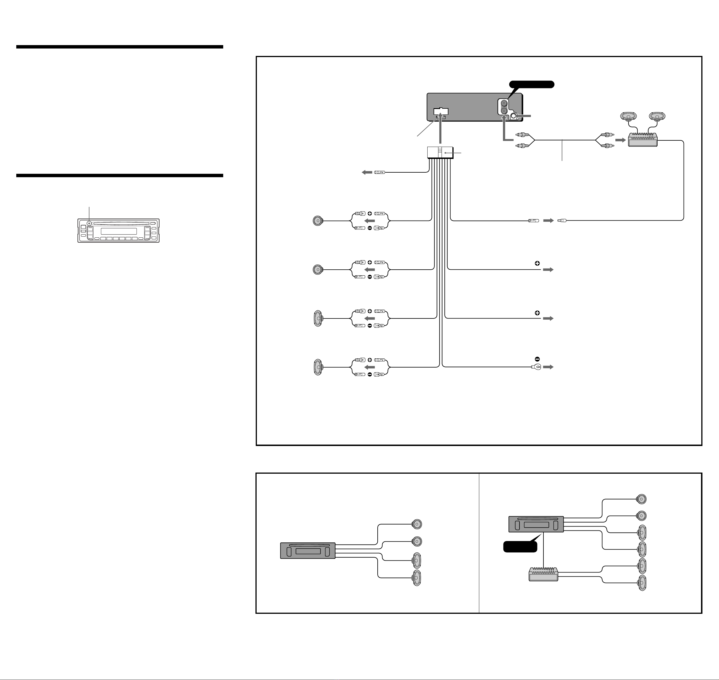
Connection exam ple
Notesonthecontrolleads
• The ANT REM lead (blue) supplies +12 V DC w hen you turn on the tuner.
• A power ant enna w it hout relay box cannot be used wit h t his unit.
Memoryholdconnection
When the yellow power input lead is connected, power w ill alw ays be supplied t o t he memory circuit even when
the ignition key is t urned of f .
RCA pin cord (not supplied)
Connections
from car antenna
Red
Yellow
Black to a metal point of the car
First connect the black ground lead, then connect the yellow and red
pow er input leads.
to the +12 V pow er terminal w hich is energized at all times
Be sure to connect the black ground lead to it first.
to the +12 V pow er terminal w hich is energized in the accessory
position of the ignition key
Be sure to connect the black ground lead to it first
White
Gray
Green
Purple
Right
Left
Rear speakers
Right
Left
Front speakers
Notesonspeakerconnection
• Before connecting the speakers, t urn the unit off.
• Use speakers w it h an impedance of 4 to 8 ohms, and wit h adequat e power handling capacities. Ot herwise, t he
speakers may be damaged.
• Do not connect the t erminals of t he speaker syst em t o the car chassis, and do not connect the t erminals of t he
right speaker wit h those of the left speaker.
• Do not at tempt t o connect the speakers in parallel.
• Do not connect any active speakers(w ith built -in amplif iers) t o t he speaker t erminals of the unit. Doing so may
damage t he active speakers. Theref ore, be sure to connect passive speakers to t hese t erminals.
Connection diagram
Exam ple 1
LINE OUT
REAR
Exam ple 2
Rear speakers
Front speakers
Pow er amplifier
Rear speakers
Rear speakers
Front speakers
AM PREM AM PREM OTEIN
M ax. supply current 0.3 A
Blue/ W hit e
to pow er antenna control lead or pow er supply
lead of antenna booster amplifier
<Note> In case of w ithout pow er antenna, or
antenna booster, not necessary to connect this
lead.
Rear speakers
Pow er amplifier
(not supplied)
LINE OUT REAR
Fuse (10 A)
8
Reset button
ANTREM
M ax. supply current 0.1 A
Blue
Downloaded from: https://www.usersmanualguide.com/


