Sony MDS-SE9 User manual

SERVICE MANUAL
Sony Corporation
Home Audio Company
Published by Sony Engineering Corporation
MDS-SE9
MD/TAPE DECK
SPECIFICATIONS
MDS-SE9 is MD deck and Tape deck
section in CMT-SE9.
Model Name Using Similar Mechanism HCD-CP505
MD Mechanism Type MDM-7S2D
Optical Pick-up Type KMS-262E
Model Name Using Similar Mechanism NEW
Tape Transport Mechanism Type CMAL2Z8
MD
Section
Tape deck
Section
Ver 1.0 2004.02
MD deck section
System Minidisc digital audio
system
Laser Semiconductor laser
(λ=780 nm)
Emission duration:
continuous
Sampling frequency 44.1 kHz
Frequency response 5 Hz – 20 kHz
Tape deck section
Recording system 4-track 2-channel stereo
Frequency response 50 – 13,000 Hz, using
Sony TYPE I cassettes
General
Power requirements 230 V AC, 50/60 Hz
Power consumption 13 W
Dimensions(w/h/d) Approx. 155 × 120 × 345 mm
Mass Approx. 4.0 kg
Design and specifications are subject to change
without notice.
UK Model
9-961-479-01
2004B1678-1
© 2004.02

2
MDS-SE9
SAFETY-RELATED COMPONENT WARNING!!
COMPONENTS IDENTIFIED BY MARK 0OR DOTTED LINEWITH
MARK 0ON THE SCHEMATIC DIAGRAMS AND INTHE PARTS
LIST ARE CRITICAL TO SAFE OPERATION. REPLACE THESE
COMPONENTS WITH SONY PARTS WHOSE PART NUMBERS
APPEAR AS SHOWN IN THIS MANUAL OR IN SUPPLEMENTS
PUBLISHED BY SONY.
This appliance is
classified as a CLASS 1
LASER product. This
label is located on the
rear exterior.
NOTES ON HANDLING THE OPTICAL PICK-UP
BLOCK OR BASE UNIT
The laser diode in the optical pick-up block may suffer electrostatic
break-down because of the potential difference generated by the
charged electrostatic load, etc. on clothing and the human body.
During repair, pay attention to electrostatic break-down and also
use the procedure in the printed matter which is included in the
repair parts.
The flexible board is easily damaged and should be handled with
care.
FOR MD
NOTES ON LASER DIODE EMISSION CHECK
Never look into the laser diode emission from right above when
checking it for adjustment. It is feared that you will lose your sight.
Laser component in this product is capable
of emitting radiation exceeding the limit for
Class 1.
Flexible Circuit Board Repairing
•Keep the temperature of the soldering iron around 270 ˚C dur-
ing repairing.
•Do not touch the soldering iron on the same conductor of the
circuit board (within 3 times).
•Be careful not to apply force on the conductor when soldering
or unsoldering.
Notes on chip component replacement
•Never reuse a disconnected chip component.
•Notice that the minus side of a tantalum capacitor may be
damaged by heat.
Unleaded solder
Boards requiring use of unleaded solder are printed with the lead-
free mark (LF) indicating the solder contains no lead.
(Caution: Some printed circuit boards may not come printed with
the lead free mark due to their particular size.)
: LEAD FREE MARK
Unleaded solder has the following characteristics.
•Unleaded solder melts at a temperature about 40°C higher than
ordinary solder.
Ordinary soldering irons can be used but the iron tip has to be
applied to the solder joint for a slightly longer time.
Soldering irons using a temperature regulator should be set to
about 350°C.
Caution: The printed pattern (copper foil) may peel away if the
heated tip is applied for too long, so be careful!
•Strong viscosity
Unleaded solder is more viscous (sticky, less prone to flow) than
ordinary solder so use caution not to let solder bridges occur such
as on IC pins, etc.
•Usable with ordinary solder
It is best to use only unleaded solder but unleaded solder may
also be added to ordinary solder.
Note 1: MDS-SE9 does not operate independently. HCD-SE9 is required to operate this.
In this case of a service, please connect HCD-SE9.
Note 2: Incorrect operations may be performed if the test mode is not entered properly.
In this case, press the ?/1button to turn the power off, and retry to enter the test mode.

3
MDS-SE9
1. SERVICING NOTES ····················································· 10
2. GENERAL ········································································ 13
3. DISASSEMBLY ······························································ 15
3-1. Top Cover ··································································· 16
3-2. Front Panel Section ···················································· 16
3-3. PANEL Board ···························································· 17
3-4. Power Transformer ····················································· 17
3-5. MD DIGITAL Board·················································· 18
3-6. MD Mechanism Deck (MDM-7S2D) ························ 18
3-7. Holder Assy ································································ 19
3-8. BD Board ··································································· 19
3-9. Loarding Motor, Spindle Motor, Sled Motor ············· 20
3-10. Over Write Head (HR901) ········································· 20
3-11. Optical Pick-up (KMS-262E) ···································· 21
3-12. Bracket (MDM)·························································· 21
3-13. MAIN Board ······························································ 22
3-14. POWER Board ··························································· 22
3-15. Tape Mechanism Deck ··············································· 23
4. TEST MODE···································································· 24
5. MECHANICAL ADJUSTMENTS ····························· 28
6. ELECTRICAL ADJUSTMENTS
TAPE SECTION ·································································· 28
MD SECTION ····································································· 30
TABLE OF CONTENTS
7. DIAGRAMS······································································ 41
7-1. Block Diagrams
– Main Section – ························································ 42
– MD Section – ·························································· 43
– USB Section – ························································· 44
7-2. Printed Wiring Board – BD Board – ··························45
7-3. Schematic Diagram – BD Board (1/2) – ···················· 46
7-4. Schematic Diagram – BD Board (2/2) – ···················· 47
7-5. Printed Wiring Board – MAIN Board (Side A) – ······ 48
7-6. Printed Wiring Board – MAIN Board (Side B) – ······ 49
7-7. Schematic Diagram – MAIN Board (1/2) – ··············· 50
7-8. Schematic Diagram – MAIN Board (2/2) – ··············· 51
7-9. Printed Wiring Board – MD DIGITAL Board – ········ 52
7-10. Schematic Diagram – MD DIGITAL Board – ··········· 53
7-11. Printed Wiring Board – PANEL Board – ··················· 54
7-12. Schematic Diagram – PANEL Board –······················ 55
7-13. Printed Wiring Board – POWER Board –·················· 56
7-14. Schematic Diagram – POWER Board – ···················· 57
7-15. IC Pin Function Description ······································ 61
8. EXPLODEDVIEWS
8-1. Overall Section ··························································· 64
8-2. Front Panel Section ···················································· 65
8-3. Chassis Section ·························································· 66
8-4. MD Mechanism Deck Section-1 (MDM-7S2D)········ 67
8-5. MD Mechanism Deck Section-2 (MDM-7S2D)········ 68
9. ELECTRICAL PARTS LIST ······································· 69

4
MDS-SE9
This system has a Self-diagnosis display
function to let you know if there is a system
malfunction. The displayshows a code madeup
of three or five letters and a message alternately
to show you the problem. To solve the problem
refer to the following list. If any problem
persists, consult your nearest Sony dealer.
C11/Protected
The MD is protected against erasure.
cRemove the MD and slide the tab to close the slot.
C12/Cannot Copy
You tried to record a disc with a format that the
system does not support, such as a CD-ROM.
cRemove the disc and turn off the system once,
then turn it on again.
You tried to record sound that cannot be digitally
recordedwiththissystemfromaconnectedoptional
component.
cSwitch the digital audio output of the optional
component to PCM mode.
C13/REC Error
Recording could not be performed properly.
cMove the system to a stable place, and start
recording over from the beginning.
The MD is dirty or scratched, or the MD does not
meet the standards.
cReplace the MD and start recording over from the
beginning.
C13/Read Error
The MD deck cannot read the disc information
properly.
cRemove the MD once, then insert it again.
Self-diagnosis display C14/TOC Error
The MD deck cannot read the disc information
properly.
cReplace the MD.
cErase all the recorded contents of the MD using
the All Erase Function.
C41/Cannot Copy
The sound source is a copy of a commercially
available music software or CD-R.
cThe Serial Copy Management System prevents
making a digital copy. In addition, you cannot
copy from a CD-R.
C71/Check OPT-IN
The digital optical cable is disconnected, or the
power of the connected component is turned off
while recording the digital audio from an optional
component connected to the VIDEO/SAT
DIGITAL IN OPTICAL jack or a CD.
cConnect the digital optical cable, or turn on the
power of the connected component.
The DVD player and the MD deck are not
connected correctly with the digital optical cable, or
you tried to start the recording immediately after
setting the recording pause mode when making a
digital recording from a optional component
connected to the VIDEO/SAT DIGITAL IN
OPTICAL jack or a CD.
cConnect the digital optical cable correctly, or wait
for several seconds in the recording pause mode
before starting the recording.
E0001/MEMORY NG
The component has internal problem.
cConsult your nearest Sony dealer.
E0101/LASER NG
There is a problem with the laser pickup.
cThe laser pickup may be damaged. Consult your
nearest Sony dealer.
E0201/LOADING NG
There is a problem with loading.
cConsult your nearest Sony dealer.

5
MDS-SE9
One of the following messages may appear or
flash in the display during operation.
Messages
MD
Analog REC
The MD deck starts the analog recording.
Assign None
All the tracks on an MD are registered into groups.
Auto Cut
The MD deck is pausing the recording because
silence continued for 30 seconds or more during
digital recording.
Blank Disc
The inserted recordable MD is new, or all tracks on
the MD have been erased.
Cannot Edit
•Apre-mastered MD is in the deck.
•Youtried to edit in Program or Shuffle Play mode.
•The track is recorded in MDLP mode.
Cannot REC
•Apre-mastered MD is in the deck.
•The function is switched to MD.
Cannot SYNC!
•There is no disc in the MD deck, or the MD is
protected against erasure.
•There is no time remaining on the MD.
Complete!
The editing operation of the MD is completed.
Disc Full!
There is no timeremaining on the MD.
Eject
The MD deck is ejecting the MD.
Group Full!
An attempt was made to create a new group in
excess of the maximum number of groups, or there
are insufficient characters for updating the group
management information.
Impossible
•You tried to make an impossible editing
operation.
•You cannot perform Net MD operations during
timer playback.
•You cannot combine or erase the tracks due to the
system limitations of MDs.
Incomplete!
Adjustment of the recording level after recording or
Fade-in and Fade-out procedures have failed since
the system was either subject to vibration or there is
a damaged or dirty disc in the tray.
Initialize
The power was off for a long time, so the system is
initializing itself.
Name Full!
There is no more space to store track, disc or group
titles.
No Change
While attempting to change the recording level after
recording, you pressed ENTER without actually
changing the recording level, so no change was
made.
No Disc
There is no disc in the MD deck.
OVER
You have reached the end of the MD while pressing
Mduring pause mode.
Push STOP!
You pressed an invalid button during playback,
pause, recording or recording pause.
Reading
The MD deck is reading the TOC information of the
MD.
—Rehearsal—
The MD is playing the specified point for
confirmation during the A-BErase Function and the
Divide Function.
S.F Edit!
You attempted to perform another operation while
in S.F Edit (changing the recording level after
recording, Fade-in, Fade-out) mode.
S.F Edit NOW
You pressed ?/1 while in S.F Edit (changing the
recording level after recording, Fade-in, Fade-out)
mode.
Smart Space
The signal was input again after silence continued
for 3 or more but less than 30 seconds during digital
recording, and the silence was cut to 3 seconds.
Step Full!
You tried to program 26 or more tracks (steps).
TOC Writing
The MD deck is writing the information of recorded
or edited contents.

6
MDS-SE9
Tr Protected
Tracks and other data thathave been checkedout on
Net MD equipment are protected, so you cannot use
some of the MD editing functions.
Tape
Cannot SYNC!
There is no tape in the tapedeck, or thetab has been
removed from the cassette.
Eject
The tape deck is ejecting the cassette.
No Tab
You cannot record the tape because the tab has been
removed from the cassette.
No Tape
There is no tape in the tape deck.
Track End
You have reached the end of the track while
adjusting the dividing point during the Divide
Function.

7
MDS-SE9
How to Operate the Self-diagnostics Function (Error History Display Mode)
Note: Use the self-diagnostics function in the "error history display mode" of the test mode. The least required procedure is described below. Do not enter any other modes by
mistake. If you have entered any other modes accidentally, press the [MODE] button to exit the mode.
1. Press the ?/1button to turn on the power.
2. Press the [FUNCTION] button to select the “MD” function. (HCD-SE9)
3. While pressing the MD xstick and the [RECMODE] button at the same time, press the Z MD button.
4. Press the MD >stick to display “[Service]”. Then press the [ENTER/START] button.
5. Press the MD >stick to display “Err Display”.
6. Press the [ENTER/START] button to enter the error history display mode and “op rec tm” appears.
7. Select the desired contents that you want to display or to execute using the MD .stick or the MD >stick.
8. Press the [TAPEREC] button to display or to execute the selected contents.
9. Press the [TAPEREC] button again to return to step 7.
10. Press the [MODE] button. The message “Err Display” appears and you exit the error history mode.
11. Press the Z TAPE button to exit the test mode.
12. Press the ?/1button to turn off the power. (HCD-SE9)
Note 1: MDS-SE9 does not operate independently. HCD-SE9 is required to operate this.
In this case of a service, please connect HCD-SE9.
Note 2: Incorrect operations may be performed if the test mode is not entered properly.
In this case, press the ?/1button to turn the power off, and retry to enter the test mode.

8
MDS-SE9
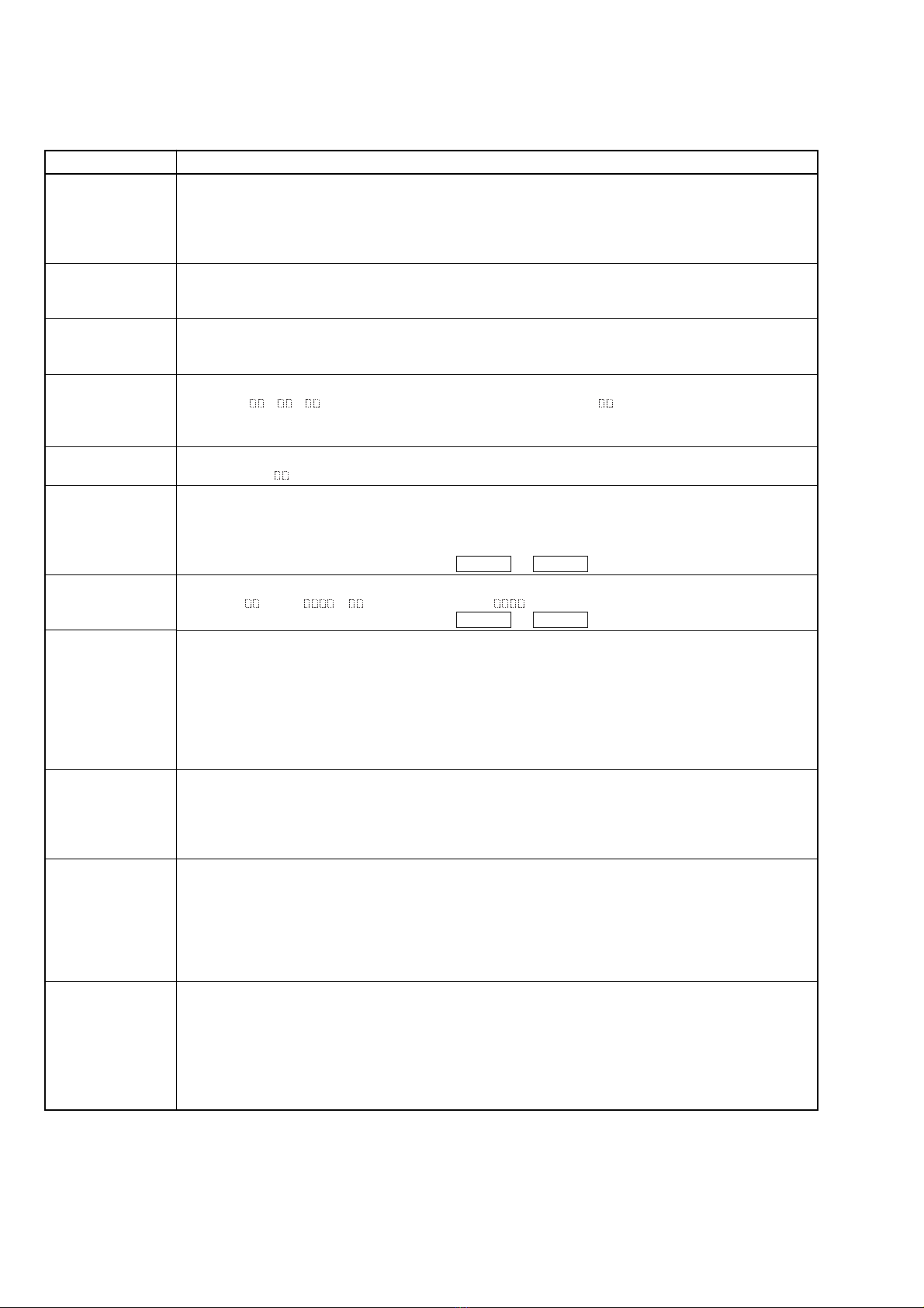
Items of Error History Mode Items and Contents
Display
op rec tm
op play tm
spdl rp tm
retry err
total err
err history
retry adrs
er refresh
tm refresh
op change
spdl change
History
Displays the accumulated recording time.
When the accumulated recording time is more than 1 minute, displays the hour and minute
When less than 1 minute, displays “Under 1 min”
The display time indicates the time when the laser is set to high power more, which is about 1/4 of the actual
recording time.
Displays the accumulated playback time.
When the accumulated playback time is more than 1 minute, displays the hour and minute
When less than 1 minute, displays “Under 1 min”
Displays the accumulated rotating time of the spindle motor.
When the accumulated rotating time is more than 1 minute, displays the hour and minute
When less than 1 minute, displays “Under 1 min”
Displays the accumulated number of retry errors during recording and playback.
Displays “r p ”. after “r” is the number of errors during recording. after “p” is the number of errors
during playback.
This is displayed in hexadecimal from 00 to FF.
Displays the total number of errors.
Displays “total ”. This is displayed in hexadecimal from 00 to FF.
Displays the past ten errors.
Displays “0X ErrCd@@”.
X is the history number. The younger the number, the more recent is the history (00 is the latest). @@ is the
error code.
Select the error history number by pressing the MD .or MD > Stick.
Displays the past five retry addresses.
Displays “ ADRS ”, is the history number, is the cluster with the retry error.
Select the error history number by pressing the MD .or MD > Stick.
Mode for erasing the error and retry address histories.
Procedure
1. Press the [TAPE REC] button when displayed as “er refresh”.
2. When the display changes to “er refresh?”, press the [ENTER/START] button
When “Complete!!” is displayed, it means erasure has completed.
Be sure to check the following after executing this mode.
*Data has been erased.
*Perform recording and playback, and check that the mechanism is normal.
Mode for erasing the accumulated recording time and accumulated playing time.
Procedure
1. Press the [TAPE REC] button when displayed as “tm refresh”.
2. When the display changes to “tm refresh?”, press the [ENTER/START] button.
When “Complete!” is displayed, it means erasure has completed.
Mode for erasing the accumulated time of op rec tm, op play tm.
Use these histories as a guide line for the time of replacement of the optical pick-up. If the optical pick-up
has been replaced, perform this procedure and erase the past history.
Procedure
1. Press the [TAPE REC] button when displayed as “op change”.
2. When the display changes to “op change?”, press the [ENTER/START] button.
When “Complete!” is displayed, it means erasure has completed.
Mode for erasing the accumulated spdl rp tm time.
Use these histories as the guide line for the time of replacement of the spindle motor. If the spindle motor has
been replaced, perform this procedure and erase the past history.
Procedure
1. Press the [TAPE REC] button when displayed as “spdl change”
2. When the display changes to “spdl change?”, press the [ENTER/START] button.
When “Complete!” is displayed, it means erasure has completed.

9
MDS-SE9
Table of Error Codes
Error Code Description
10
11
12
20
21
22
23
24
30
31
40
41
42
43
50
51
60
Could not perform loading
The changer error occurred
Loading switches combined incorrectly
Timed out without reading the top of PTOC
Could read top of PTOC, but detected error
Timed out without accessing UTOC
Timed out without reading UTOC
Error in UTOC
Could not start playback
Error in sector
A cause of retry occurred during normal recording
Retried due to DRAM overflow
Retry occurred during TOC writing
Retry aborted during S.F editing
Other than access processing, and could not read address.
Focus NG occurred and overran.
High speed synchronize recording of unlock retry.

10
MDS-SE9 SECTION 1
SERVICING NOTE
Service Position (CheckingTC)
DisassembletheMD mechanism deck andtheMD DIGITAL board.
Connect the wire (flat type, 25 cores) as shown in the figure to
check the tape mechanism.
wire (flat type)
(25 core)
MD mechanism deck
(MDM-7S2D)
tape mechanism deck
MD DIGITAL board
Please put MD mechanism deck on a rest with
an insulation sheet etc.

11
MDS-SE9
Jig For Checking BD Board Waveform
The special jig (J-2501-196-A) is useful for checking the waveform of the BD board. The names of terminals and the checking items to be
performed are shown as follows.
I+3V : For measuring Iop (Check the deterioration of the optical pick-up laser)
Iop : For measuring Iop (Check the deterioration of the optical pick-up laser)
GND : Ground
TE : TRK error signal (Traverse adjustment)
FE : Focus error signal
VC : Reference level for checking the signal
RF : RF signal (Check jitter)
I+3V
CN105
IopTE
VC
GND
FE RF
I+3V
Iop
GND
TE
FE
VC
RF
I+3V
Iop
GND
TE
FE
VC
RF
1
7
for MDM-7S2
D

12
MDS-SE9
Iop DATA RECORDING AND DISPLAYWHEN OPTICAL PICK-UP AND NON-VOLATILE MEMORY (IC195 OF
BD BOARD) ARE REPLACED
The Iop value labeled on the optical pick-up can be stored in the non-volatile memory. By storing the value, it will eliminate the need to look
at the value on the label of the optical pick-up.When replacing the optical pick-up or non-volatile memory (IC195 of BD board), store the Iop
value on the optical pick-up according to the following procedure.
Record Precedure:
1. Press the ?/1button to turn on the power. (HCD-SE9)
2. Press the [FUNCTION] button to select the “MD” function. (HCD-SE9)
3. While pressing the MD xstick and the [RECMODE] button at the same time, press the Z MD button.
4. Press the MD >stick to display “[Service]”. Then press the [ENTER/START] button.
5. Press the MD >stick to display “Iop Write” (C05) and press the [ENTER/START] button.
6. The display becomes “Ref=@@@.@” (@ is an arbitrary number) and the numbers which can be changed will blink.
7. Input the Iop value written on the optical pick-up.
To select the number : Press the MD .stick or the MD >stick.
To select the digit : Press the [TAPE REC] button.
8. When the [ENTER/START] button is pressed, the display becomes “Measu=@@@.@” (@ is an arbitrary number).
9. As the adjustment results are stored for the 8 value. Leave it as it is and press the [ENTER/START] button.
10. “Complete!” will be displayed momentarily. The value will be stored in the non-volatile memory and the display will become “Iop
Write” (C05).
11. Press the Z TAPE button to exit the mode.
12. Press the ?/1button to turn off the power. (HCD-SE9)
Display Precedure:
1. Press the ?/1 button to turn on the power. (HCD-SE9)
2. Press the [FUNCTION] button to select the “MD” function. (HCD-SE9)
3. While pressing the MD xstick and the [RECMODE] button at the same time, press the ZMD button.
4. Press the MD >stick to display “[Service]”. Then press the [ENTER/START] button.
5. Press the MD >stick to display “Iop Read” (C26) and press the [ENTER/START] button.
6. “@@.@/##.#” is displayed and the recorded contents are displayed.
@@.@ : indicates the Iop value labeled on the optical pick-up
##.# : indicates the Iop value after adjustment
7. To end, press the [MODE] button to display “Iop Read” (C26). Then press the ZTAPE button.
8. Press the ?/1 button to turn off the power. (HCD-SE9)
Checks Prior to Parts Replacement and Adjustments in MD
Before performing repairs, perform the following checks to determine the faulty locations up to a certain extent.
Details of the procedures are described in “SECTION 6 ELECTRICAL ADJUSTMENTS”.
Note:
The criteria for determination above is intended merely to determine if satisfactory or not, and does not serve as the specified value for adjustments.
When performing adjustments, use the specified values for adjustments.
•0.93 mW power
Specified value : 0.84 to 0.92 mW (KMS-262A)
0.90 to 0.96 mW (KMS-262E)
•8.65 mW power
Specified value : 8.1 to 8.7 mW (KMS-262A)
8.4 to 8.9 mW (KMS-262E)
•Iop (at 8.65 mW)
Labeled on the optical pick-up
Iop value ± 10mA
•Unsatisfactory if displayed as “NG : XXXX”
(XXXX are arbitrary numbers)
•Unsatisfactory if displayed as “T=@@ (##) [NG]”
(@@, ## are both arbitrary numbers)
Laser power check
(6-2 : See page 33)
Auto check
(6-4 : See page 34)
Temperature
compensation
offset check
(6-1 : See page 33)
Criteria for Determination
(Unsatisfactory if specified value is not satisfied) •Clean the optical pick-up
•Adjust again
•Replace the optical pick-up
•Check for disconnection of the circuits around
D101 (BD board)
•Check the signals around IC101, IC151, CN102,
CN103 (BD board)
Measure if unsatisfactory

13
MDS-SE9
SECTION 2
GENERAL This section is extracted
from instruction manual.
Main unit
DIRECTION 8
DISPLAY 3
Display window 1
ENTER/START 9
MD lever 4
MD slot 5
MODE 9
NET MD 2
REC 8
REC MODE 7
REC/REC IT 7
TAPE lever 6
TAPE slot qa
x(stop) 46
./> (go back/go forward)
4
NX (play/pause) 4
ZMD (eject) qs
ZTAPE (eject) q;
X(pause) 8
nN (play) 6
m/M (rewind/fast forward)
6
ALPHABETICAL ORDER
A – M N – Z
BUTTON DESCRIPTIONS
23
146578
9qsqaq;
AC OUTLET
SYSTEM
CONTROL
DIGITAL OUT
OPTICAL
D
DIGITAL IN
OPTICAL
C
MD
OUT B
MD/TAPE
IN A
RL
RL
USB

14
MDS-SE9
Remote control
ALBUM +/–* qd
ANGLE* 8
AUDIO* 8
CLEAR w;
CLOCK/TIMER SELECT qs
CLOCK/TIMER SET qs
DDSG qf
DVD DISPLAY* 9
DVD MENU* qd
DVD SETUP* wf
ENTER qh
FM MODE ws
FUNCTION ql
GROUP SKIP 7
MD GROUP 7
MENU/NO 4
NAME EDIT/SELECT 0
Number buttons 3
PC LIB wa
PLAY MODE qk
REPEAT ws
SCROLL wd
SLEEP 2
SOUND FIELD +/– 6
SPEAKER OUT MODE qj
SUBTITLE* 8
TOP MENU* qd
TUNER BAND qg
TUNING MODE qk
VOLUME +/– qa
?/1 (power) 1
MD N(play) 5
PC N(play) 5
SA-CD/DVDN/SELECT(play)
5
TAPE nN (play) 5
+/– qh
X(pause) qh
x(stop) qh
v/V/b/B qh
m/M (rewind/fast forward)
qh
./> (go back/go forward)
qh
/y (slow review/slow play)
qh
RETURN O*wg
*Please operate with the cover
closed.
ALPHABETICAL ORDER
A – F G – Z
BUTTON DESCRIPTIONS
1
2
3
4
5
6
7
8
9
0
qa
qs
qd
qg
qf
qh
qk
qj
ql
w;
wa
wf
ws
wd
wg

15
MDS-SE9
• The equipment can be removed using the following procedure.
• The dotted square with arrow ( ) prompts you to move to the next job when all of the works within the dotted square ( ) are completed.
SECTION 3
DISASSEMBLY
SET
TOP COVER
FRONT PANEL SECTION MD DIGITAL BOARD POWER TRANSFORMER
PANEL BOARD BRACKET (MDM)
MAIN BOARD
MD MECHANISM DECK
(MDM-7S2D)
POWER BOARDHOLDER ASSY
BD BOARD
LOADING MOTOR ASSY,
SPINDLE MOTOR ASSY,
SLED MOTOR ASSY
OVER WRITE HEAD
(HR901)
OPTICAL PICK-UP
(KMS-262E)
TAPE MECHANISM DECK

16
MDS-SE9
4
two screws
(+BV sumitite B3 3
×
6)
1
wire (flat type)
(13core) (CN181)
8
front panel section
3
Peel off the himeron tape.
2
earth wire
7
claw
6
claw
5
claw
3-1. TOP COVER
Note: Follow the disassembly procedure in the numerical order given.
4
top cover
1
two screws
(+BVTP 3
×
8)
3
case screw
2
case screw
3-2. FRONT PANEL SECTION

17
MDS-SE9
2
wire (flat type)
(13 core) (CN801
)
1
eight screws
(+BV 2.6
×
8)
3
PANEL board
1
four screws
(+BVTP 3
×
8
)
4
power transformer
2
connector
(CN51)
3
connector
(CN2)
3-3. PANEL BOARD
3-4. POWERTRANSFORMER

18
MDS-SE9
3-5. MD DIGITAL BOARD
3-6. MD MECHANISM DECK (MDM-7S2D)
2
wire (flat type)
(25 core)
1
two screws
(+BVTP 3
×
8)
(CN703)
(CN501)
5
MD DIGITAL board
4
connector
(CN704)
3
connector
(CN705)
4
screw
(+BVTP 3
×
8)
1
four step screws
(+BVTTWH M3)
3
two insulators
7
MD mechanism deck
(MDM-7S2D)
2
two insulators
5
wire (flat type)
(17core) (CN702)
6
wire (flat type)
(23core) (CN701)

19
MDS-SE9
3-7. HOLDER ASSY
3-8. BD BOARD
3
holder assy
1
tension spring (holder)
2
hook
1
Remove the
two solderings.(sled motor)
2
Remove the
two solderings.(spindle motor)
3
Remove the
two solderings.
(loading motor)
4
Remove the
three solderings.
M102
M101
M103
S102
6
flexible board
(CN101)
7
connector cable (CN104)
8
BD board
5
two screws
(+B (P) TRI 2
×
6 CZN)

20
MDS-SE9
3-9. LOARDING MOTOR, SPINDLE MOTOR, SLED MOTOR
3-10. OVER WRITE HEAD (HR901)
1
lever (head)
2
belt (loading)
3
torsion spring (spindle)
9
gear (sa)
4
two screws
(PWH 1.7
×
3.5)
0
two screws
(PWH 1.7
×
2.5)
8
tapping screw
(M1.7 )
qa
sled motor ass
y
(M102)
6
three tapping screws
(M1.7 )
5
loading motor assy
(M103)
7
spindle motor assy
(M101)
1
screw (P 1.7
×
6)
2
over write head
(HR901)
Table of contents
Other Sony CD Player manuals

Sony
Sony CDX-F5510 (XT-XM1) Product guide

Sony
Sony CDX-G3150UV User manual

Sony
Sony Walkman D-NE270 User manual

Sony
Sony CDX-R3350 User manual

Sony
Sony D-NE518CK - Portable Cd Player User manual

Sony
Sony Discman D-E303 User manual

Sony
Sony MDP-650 User manual

Sony
Sony CDP-C591 User manual

Sony
Sony D-F400 User manual

Sony
Sony CFD-C646 User manual

Sony
Sony CDX-626 User manual

Sony
Sony MZ-M10 User manual

Sony
Sony CDP-CX260 - 200 Disc Cd Changer User manual

Sony
Sony MCE-F88K User manual

Sony
Sony Walkman D-FJ003 User manual

Sony
Sony CFDG770CPK User manual

Sony
Sony CDX-52RF Product guide

Sony
Sony D-E990 User manual

Sony
Sony CDX-R3300T Product guide

Sony
Sony CDP-XE530 User manual